Issue 5 November 2000
363-206-208
DDM-2000 OC-3/OC-12 Bay Installation
Lucent Technologies - Proprietary
See Notice on first page
NOTE:
Each feeder will be fused for at least 25 amperes for DDM-2000 bay arrange-
ments.
NOTE:
The C. O. battery and ground cables must be a minimum of 10 gauge for DDM-
2000 bay arrangements.
Bays with Fuse Panel
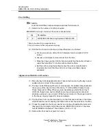
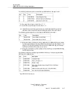
When the DDM-2000 bay is equipped with a fuse panel, provide office power to the
DDM-2000 bay as follows:
1. Remove the BDFB fuses or set the breakers to off until you are ready to
do the “Powering, Verification and Circuit Pack installation” section in this
manual.
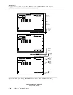
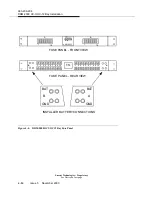
2. Remove the cover from the rear of the fuse panel. See Figure 4-4 on page
4-14.
3. Label the four Central Office feeders from the BDFB at the DDM-2000 bay
as BAT A, BAT B, GRD A, and GRD B.
4. Prepare the ends of “A” feeders and attach lugs. Connected the “A” bat-
tery power feeder to the “A BAT” and the “A” ground feeder to “A GRD” on
the fuse panel. See Figure 4-4 on page 4-14.
NOTE:
Fuse panel lugs are not furnished with the DDM-2000 bay.
5. Prepare the ends of “B” power feeders and attach lugs. Connected the “B”
battery power feeder to the “B BAT” and the “B” ground feeder to “B GRD”
on the fuse panel
6. Dress and tie the battery and ground cables as required.
7. Remount the cover on the rear of the fuse panel.
NOTE:
Leave the BDFB fuses out or breakers off until you are ready to do the “Power-
ing, Verification and Circuit Pack installation” section in this manual.
Summary of Contents for DDM-2000 OC-12
Page 4: ......
Page 370: ...GL 22 Issue 5 June 2000 363 206 208 Glossary ...
Page 382: ...363 206 208 Index 1 ...


