Issue 5 November 2000
363-206-208
Powering, Verification, and Circuit Pack Installation for the DDM-2000 OC-12 Multiplexer
Lucent Technologies - Proprietary
See Notice on first page
Circuit Pack Installation
The following procedure provides the recommended order for circuit pack installation.
NOTE:
A wrist strap MUST be worn when handling circuit packs.
NOTE:
Circuit packs are keyed to prevent being inserted into the wrong shelf position.
NOTE:
When installing the circuit packs, be careful to insert them straight to avoid dam-
aging the LEDs.
NOTE:
When a circuit pack is installed, its FAULT LED will light for several seconds then
extinguish.
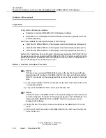
NOTE:
The UPD/INIT push-button on the BBG5 or BBG8 SYSCTL circuit pack is
recessed and will require a pointed object, like a ballpoint pen, to press it.
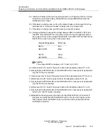
For circuit packs that have latches on the bottom as well as the top of the faceplate,
insert per the following method:
(1) Insert circuit pack into slot with both latches in the fully open position. Push pack
in until the latches clear the key strip area and latches can engage on latch
channel on shelf.
(2) Apply a small amount of force to both the top and bottom latch evenly and simul-
taneously.
(3) Do not apply excess force, the connectors of these packs do not need a high
level of force to mate. If excessive resistance is met, withdraw pack slightly to
remove cause of binding and continue with Step 2.
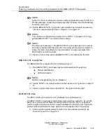
NOTE:
All other circuit packs require some force to insert.
NOTE:
To add a circuit pack to the SYSCTL’s equipment list, the circuit pack needs only
to be installed. However, to delete a circuit pack from the SYSCTL’s equipment
list, an UPD/INIT must be performed after the circuit pack is unseated. Other-
wise, the system will alarm.
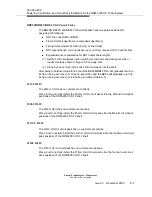
(4) Fully insert the BCP2 or BCP3 TSI circuit packs into the shelf.
Summary of Contents for DDM-2000 OC-12
Page 4: ......
Page 370: ...GL 22 Issue 5 June 2000 363 206 208 Glossary ...
Page 382: ...363 206 208 Index 1 ...

