Issue 5 November 2000
363-206-208
End-To-End Installation Tests for Ring Applications of the DDM-2000 OC-12 Multiplexer
Lucent Technologies - Proprietary
See Notice on first page
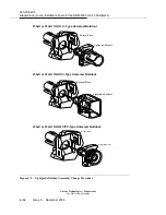
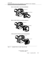
(3) Replace the 15 dB or 20 dB lightguide buildout assembly on the OUT (transmit)
connector with a 0 dB buildout assembly per Figure 7-1 on page 7-17.
NOTE:
The 0 dB buildout was replaced by a 15 dB or 20 dB buildout in the “Stand-Alone
Installation Tests” section.
Optical Power Measurement
!
WARNING:
Unterminated optical connectors may emit laser radiation. Do not view beam
with optical instruments.
!
WARNING:
Invisible laser radiation when open. Avoid direct exposure to beam.
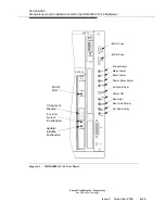
(1) At the first node of the ring, connect the optical fiber transmit cable that is to
transmit in the clockwise direction of the ring, to the DDM-2000 OC-12 23-type
MAIN-B-2 OLIU OUT connection and fully insert the OLIU into the shelf.
(2) At the next node in the clockwise direction, measure the optical power of the
optical fiber receive cable (same fiber connected to the OLIU in the previous
step) using the optical power meter.
(3) If the optical power reading is less than or equal to -8.0 dBm for a 23G-U and
23H-U OLIU, the 0 dB buildout assembly will remain on the OUT connector of
the OLIU.
(4) If the optical power reading is greater than the value in Step 3 above, replace
the 0 dB buildout assembly on the OUT connector of the OLIU per Figure 7-1 on
page 7-17 with the appropriate buildout assembly that will attenuate the power
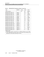
reading to be slightly less than or equal to this value. Table 7-1 on page 7-5 lists
the various lightguide buildout assemblies available.
Summary of Contents for DDM-2000 OC-12
Page 4: ......
Page 370: ...GL 22 Issue 5 June 2000 363 206 208 Glossary ...
Page 382: ...363 206 208 Index 1 ...

