Issue 5 November 2000
363-206-208
Equipment and Rear Access Cabling for the DDM-2000 OC-12 Multiplexer
Lucent Technologies - Proprietary
See Notice on first page
Procedure
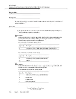
(1) Mount the DDM-2000 OC-12 shelves, fan shelves, and heat baffles in a network
bay frame with the wide flange of the bay frame to the front as shown in Figure
2-5 on page 2-52. Position the shelves and heat baffles in the bay frame as
shown in Figure 2-6 on page 2-53 and Figure 2-7 on page 2-54 for DDM-2000
OC-3/OC-12 combined bay. Use the hardware provided in the installation kits to
mount the shelves and baffles. When installing the fan shelves, refer to the “Fan
Shelf Installation” procedure.
NOTE:
For a DDM-2000 OC-3/OC-12 combined bay arrangement, the lightguide slack
storage shelf is mounted with the top hole of the mounting brackets aligned with
the third mounting hole up from the bottom of the bay. The DDM-2000 OC-12
shelf then mounts three inches above the slack storage shelf as shown in Figure
2-7 on page 2-54.
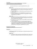
(2) Verify with an ohmmeter that the DDM-2000 OC-12 is grounded to the bay
frame.
(3) Install the required shelf brackets as shown in Figure 2-5 on page 2-52 and Fig-
ure 2-6 on page 2-53.
NOTE:
For an ED-8C501-50 or ED-8C801-50 type frame, there are two brackets
required per shelf to hold the fiber protection channel for the optical fiber cables
in place.
(4) Install the required fiber protection channel for the optical fiber cables as shown
in Figure 2-5 on page 2-52 and Figure 2-6 on page 2-53.
Fan Shelf Installation - Rear Access
Description
This procedure describes how to install the fan shelf.
Procedure
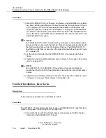
The WP-92311, L5 fan shelf mounts directly above a DDM-2000 OC-12 shelf. Refer to
Figure 2-6 on page 2-53 and Figure 2-7 on page 2-54.
(1) Reposition the fan shelf mounting brackets, if necessary, to fit within the bay
footprint for the DDM-2000 OC-12 shelf.
Summary of Contents for DDM-2000 OC-12
Page 4: ......
Page 370: ...GL 22 Issue 5 June 2000 363 206 208 Glossary ...
Page 382: ...363 206 208 Index 1 ...

