Issue 5 November 2000
363-206-208
Equipment and Rear Access Cabling for the DDM-2000 OC-12 Multiplexer
Lucent Technologies - Proprietary
See Notice on first page
Power Cabling - Rear Access
Description
Two feeders (A and B) are required from the battery distribution fuse board (BDFB) to
the DDM-2000 OC-12 bay.
Power Cable Installation
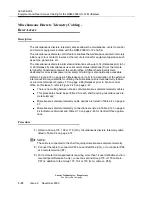
(1) Obtain either a single shelf power cable or a bay power cable. The bay power
cable is configured to power up to three DDM-2000 OC-12 shelves and up to
three fan shelves. Refer to Table 2-7 on page 2-40.
NOTE:
The bay power cable assembly has three break points with three cables at each
break point. The bay power cable should be positioned so that break points are
located in the bay such that each break point is lined up with its corresponding
DDM-2000 OC-12 shelf. At each break point, one cable connects to the corre-
sponding DDM-2000 OC-12 shelf and one cable connects to the fan shelf
directly above the DDM-2000 OC-12 shelf. The remaining cable in the break
point is not used.
NOTE:
If the bottom shelf position is not being equipped and a bay power cable assem-
bly is being installed, locate the breakouts on the cable so that a connector will
be available for future addition of the shelf.
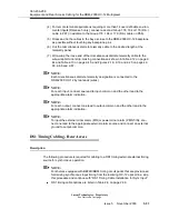
(2) For each DDM-2000 OC-12 shelf:
a. Locate the ED-8C727-20, Group 150 DDM-2000 OC-12 shelf power
cable.
b. Prepare the ends of the wires on the cable and insert them into the J25
terminal strip on the rear of the shelf per Figure 2-12 on page 2-59 and
the following table:
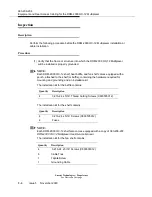
Terminal Designation
Wire Color
-48 VA
Red
RTNA
Black
-48 VB
Green
RTNB
White
Summary of Contents for DDM-2000 OC-12
Page 4: ......
Page 370: ...GL 22 Issue 5 June 2000 363 206 208 Glossary ...
Page 382: ...363 206 208 Index 1 ...

