363-206-295
Transmission and Synchronization Interfaces
5-2
Issue 1
December 1997
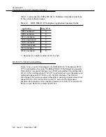
Table 5-1 summarizes the DDM-2000 OC-12 Multiplexer transmission interfaces
for the current software release.
OC-12 STS-1 Path Switched Ring
5
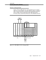
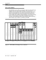
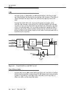
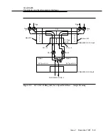
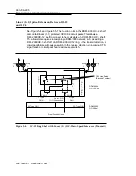
Figure 5-1 is an overall block diagram of a DDM-2000 OC-12 Multiplexer STS-1/
VT1.5 path switched ring node. The DDM-2000 OC-12 Multiplexer ring supports
DS3 and EC-1 low-speed interfaces in an STS-1 path switched ring configuration,
0x1 OC-3/IS-3 interfaces in an STS-1/VT1.5 path switched ring configuration, and
optical extensions with OC-3/IS-3 or OC-3c/IS-3c interfaces. The time slot
interchange (TSI) feature provides full flexibility in assigning signals between low-
speed DS3, OC-3/OC-3c/IS-3/IS-3c, and EC-1 ports and the high-speed
interface. Each function unit can handle a maximum of 3 STS-1s for a total of 12
STS-1s or one STS-3c for a total of 4 STS-3cs.
Table 5-1.
DDM-2000 OC-12 Multiplexer Application Summary Matrix
Application
Ring (R7.0)
DS1 Low-speed *
X
DS3 Low-speed
X
EC-1 Low-speed
X
OC-12 High-speed
X
OC-3 Low-speed
X
OC-3c Low-speed
X
IS-3 Low-speed
X
IS-3c Low-speed
X
∗
Requires OC-3 shelf in addition to OC-12 shelf.


