Issue 1
December 1997
9-1
9
Maintenance Description
9
Overview
9
This section defines the "maintenance philosophy" outlining the various features
available to monitor and maintain the DDM-2000 OC-12 Multiplexer. Specific
trouble clearing and maintenance procedures are provided in the operation and
maintenance (TOP) section of this manual (Volume II).
Three-Tiered Operations
9
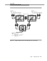
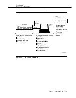
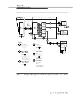
Figure 9-1 shows the three-tiered operations procedures for the DDM-2000
OC-12 Multiplexer. The DDM-2000 OC-12 Multiplexer operations procedures are
built on three levels of system information and control, spanning operations needs
from summary-level status to detailed reporting.
The first operations tier consists of light-emitting diodes (LEDs) and pushbuttons
on the user panel and circuit pack faceplates. These allow routine tasks to be
performed without a craft interface terminal (CIT) or any test equipment. The user
panel provides system-level alarm and status information for the local terminal.
The circuit pack faceplate FAULT LEDs allow fast and easy fault isolation to a
particular circuit pack. The user panel and equipment indicators are described in
Chapter 6, “Operation Interfaces.”
The second operations tier provides access to DDM-2000 OC-12 Multiplexer
operations from a CIT over an EIA-232-D interface. System details that cannot be
obtained from the first operations tier alone can be obtained over the CIT
interface. A VT-100 compatible terminal or terminal emulator software running on
a personal computer (PC) can be used as a CIT. Command and prompt modes


