background image

Contents

11-75

System

Initialize

INIT-SYS

11-82

Program

Install

INS-PROG

11-90

Logout

LOGOUT

11-91

Cutoff

Alarm

Operate

OPR-ACO

11-92

EC-1

Loopback

Operate

OPR-LPBK-EC1

11-94

T3

Loopback

Operate

OPR-LPBK-T3

11-98

Reset

RESET

11-100

Login

Remote

RLGN

11-104

EC-1

Loopback

Release

RLS-LPBK-EC1

11-105

T3

Loopback

Release

RLS-LPBK-T3

11-106

Passwords

and

Logins

Restore

RSTR-PASSWD

11-109

Conditions

Status

&

Alarm

Retrieve

RTRV-ALM

11-110

Alarm

Attribute

Retrieve

RTRV-ATTR-ALM

11-112

Control

Attribute

Retrieve

RTRV-ATTR-CONT

11-114

Environment

Attribute

Retrieve

RTRV-ATTR-ENV

11-116

STS-1

Cross-Connection

Retrieve

RTRV-CRS-STS1

11-119

STS-3c

Cross-Connection

Retrieve

RTRV-CRS-STS3c

11-121

EC-1

Retrieve

RTRV-EC1

11-123

Equipment

Retrieve

RTRV-EQPT

11-127

Feature

Retrieve

RTRV-FEAT

11-128

Communications

End

Far

Retrieve

RTRV-FECOM

11-130

History

Retrieve

RTRV-HSTY

11-131

Login

Retrieve

RTRV-LGN

11-133

Link

Retrieve

RTRV-LINK

11-135

Neighbor

Map

Retrieve

RTRV-MAP-NEIGHBOR

11-139

Network

Map

Retrieve

RTRV-MAP-NETWORK

11-143

Element

Network

Retrieve

RTRV-NE

11-146

OC-3

Retrieve

RTRV-OC3

11-149

OC-12

Retrieve

RTRV-OC12

11-151

Map

ID

Context

App.

OS

Retrieve

RTRV-OSACMAP

11-154

Password

Retrieve

RTRV-PASSWD

11-156

Line

Monitoring

Performance

Retrieve

RTRV-PM-LINE

11-159

Section

Monitoring

Performance

Retrieve

RTRV-PM-SECT

11-162

STS-1

Monitoring

Performance

Retrieve

RTRV-PM-STS1

11-165

T3

Monitoring

Performance

Retrieve

RTRV-PM-T3

11-169

TCA

Monitoring

Performance

Retrieve

RTRV-PM-TCA

11-171

Line

Threshold

Monitoring

Performance

Retrieve

RTRV-PMTHRES-LINE

11-173

Section

Threshold

Monitoring

Performance

Retrieve

RTRV-PMTHRES-SECT

11-175

STS-1

Threshold

Monitoring

Performance

Retrieve

RTRV-PMTHRES-STS1

11-177

T3

Threshold

Monitoring

Performance

Retrieve

RTRV-PMTHRES-T3

11-180

Security

Retrieve

RTRV-SECU

11-183

Equipment

State

Retrieve

RTRV-STATE-EQPT

11-188

OC-3

State

Retrieve

RTRV-STATE-OC3

11-190

Path

State

Retrieve

RTRV-STATE-PATH

11-ii

1997

December

1

Issue

Summary of Contents for DDM-2000 OC-12

Page 1: ...363 206 295 Issue 1 December 1997 DDM 2000 OC 12 Multiplexer Release 7 0 User Service Manual Volume I ...

Page 2: ...fic Lucent Technologies cannot be responsible for such charges and will not make any allowance or give any credit for charges that result from unauthorized access Trademarks 5ESS DACScan LGX SLC ST and Western Electric are registered trademarks of Lucent Technologies Inc ANSI is a registered trademark of American National Standards Institute Inc Common Language is a registered trademark and CLEI C...

Page 3: ...ce and Technical Support The Lucent Technologies Regional Technical Assistance Center RTAC provides a technical assistance telephone number which is staffed 24 hours a day For technical assistance simply call 1 800 225 RTAC in accordance with local operating procedures Documentation Support Telephone Number Lucent Technologies provides a telephone number for you to report errors or to ask question...

Page 4: ...re figures Make it less technical Add more examples Add more better quick reference aids Add more detail Improve the index Please provide details for the suggested improvement 3 What did you like most about this CIP 4 Feel free to write any comments below or on an attached sheet If we may contact you concerning your comments please complete the following Name Telephone Number Company Organization ...

Page 5: ...RST CLASS PERMIT NO 1999 GREENSBORO NC POSTAGE WILL BE PAID BY ADDRESSEE NO POSTAGE NECESSARY IF MAILED IN THE UNITED STATES Do Not Cut Fold Here And Tape DOCUMENTATION SERVICES 2400 Reynolda Road Winston Salem NC 27199 2029 ...

Page 6: ...re figures Make it less technical Add more examples Add more better quick reference aids Add more detail Improve the index Please provide details for the suggested improvement 3 What did you like most about this CIP 4 Feel free to write any comments below or on an attached sheet If we may contact you concerning your comments please complete the following Name Telephone Number Company Organization ...

Page 7: ...RST CLASS PERMIT NO 1999 GREENSBORO NC POSTAGE WILL BE PAID BY ADDRESSEE NO POSTAGE NECESSARY IF MAILED IN THE UNITED STATES Do Not Cut Fold Here And Tape DOCUMENTATION SERVICES 2400 Reynolda Road Winston Salem NC 27199 2029 ...

Page 8: ...autions for Unenclosed Systems xlvii Electrostatic Discharge ESD Considerations xlvii Related Documentation lii Related Training lix Customer Technical Support CTS lxii Engineering and Installation Services lxvi Customer Technical Support Enhanced Services lxvii Documentation Support lxvii How to Order Documents lxviii Standing Orders lxix How to Comment on This Document lxx Electronic Documentati...

Page 9: ...ear Optical Extensions from OC 3 and OC 12 Rings 2 22 OC 12 Point to Point Folded Ring 2 24 2000 Product Family Interworking 2 26 SLC 2000 Access System 2 26 FT 2000 OC 48 Lightwave System 2 27 Multi Vendor OI Applications 2 28 Service Applications 2 29 Loop Feeder 2 29 Interoffice Transport 2 29 Broadband Business Access 2 30 STS 3c Video Broadcast Application 2 32 STS 3c Video Application ATM In...

Page 10: ...nfiguration 3 11 OC 12 Ring Configuration DS1 EC 1 Low Speed Interfaces 3 12 OC 12 Optical Extension Shelf 3 13 Linear 1 1 Extension From OC 12 Ring Configuration 3 14 OC 12 Dual Homing Shelf 3 15 OC 12 STS 3c Broadcast Shelf 3 16 OC 12 OC 3c Transport Shelf 3 17 DDM 2000 Fan Shelf 3 18 4 Power Overview 4 1 Introduction 4 1 Power Description 4 2 Circuit Packs 4 3 OLIU Circuit Packs 4 3 TSI TGS TG3...

Page 11: ...10 Holdover 5 11 DS1 Output Modes MULT and SYNC OUT 5 11 DS1 Output Mode MULT 5 11 DS1 Output Mode SYNC OUT 5 12 Synchronization Messaging 5 16 Applications 5 16 DS1 Timing Output Integrity 5 17 Automatic Synchronization Reconfiguration 5 19 Synchronization Provisioning Integrity 5 21 Feature Details and Options 5 21 Examples 5 24 Synchronization Reconfiguration Using an Externally Timed Access Ri...

Page 12: ...d Provisioning Tool 6 8 User Panel 6 8 User Panel LEDs 6 10 FE SEL Pushbutton 6 10 ACO TST Pushbutton 6 10 UPD INIT Pushbutton 6 11 Pushbutton Combinations 6 11 Equipment Indicators 6 12 FAULT Indicators 6 12 ACTIVE Indicators 6 12 Office Alarms 6 13 TL1 X 25 Interface 6 14 ITM SNC 6 15 IAO LAN Interface 6 15 User Definable Miscellaneous Discretes Environmental Alarms and Controls 6 16 7 Circuit P...

Page 13: ...Overhead Channel 7 8 Power Monitoring and Fan Control 7 9 Interface to Other DDM 2000 OC 12 Shelves 7 9 Power Circuitry 7 9 BBG8 BBG8B SYSCTL Hardware Setting 7 10 BBG8 BBG8B SYSCTL Quick Reference Summary 7 11 Interface Functions 7 11 User Panel 7 11 Telemetry Functions 7 11 Maintenance Functions 7 11 BCP4 OHCTL Circuit Pack Description 7 12 Purpose of Circuit 7 12 Faceplate Indicator 7 12 Genera...

Page 14: ...Detailed Description of Operation 7 19 Control Circuitry 7 19 Timing Circuitry 7 20 Clock Output Functions 7 21 Protection Circuitry 7 21 Fault Detection Circuitry 7 22 Power Circuitry 7 22 TG Hardware Settings 7 22 TG Quick Reference Summary 7 24 Provisioned Modes 7 24 Holdover Mode 7 24 Maintenance and Control 7 24 DS1 Output 7 24 Transmission 7 25 BBG11 3DS3 Circuit Pack Description 7 25 Purpos...

Page 15: ...cators 7 32 General Description of Operation 7 33 Detailed Description of Operation 7 33 Transmission Circuitry 7 33 Control Circuitry 7 35 Timing Circuitry 7 35 Protection Circuitry 7 35 Fault Detection Circuitry 7 36 Loopbacks 7 36 Performance Monitoring 7 36 Power Circuitry 7 37 BBG11B 3DS3 Hardware Settings 7 37 BBG11B 3DS3 Quick Reference Summary 7 38 Transmit Functions 7 38 Receive Functions...

Page 16: ...ription 7 46 Purpose of Circuit 7 46 BCP3 Faceplate Indicators 7 46 General Description of Operation 7 47 Detailed Description of Operation 7 47 Transmission Circuitry 7 47 Clock and Frame SYNC Distribution 7 47 Maintenance Features and Modes 7 49 Power Circuitry 7 49 BCP3 Quick Reference Summary 7 50 Interface Functions 7 50 Control Functions 7 50 Maintenance Functions 7 50 21D 21D U OLIU Circuit...

Page 17: ...escription of Operation 7 57 Detailed Description of Operation 7 57 Transmission Circuitry 7 59 Control Circuitry 7 59 Timing Circuitry 7 59 Protection Circuitry 7 60 Fault Detection Circuitry 7 60 Performance Monitoring 7 60 Power Circuitry 7 60 21G 21G U OLIU Hardware Settings 7 61 21G 21G U 21G2 U OLIU Quick Reference Summary 7 62 Transmit Functions 7 62 Receive Functions 7 62 Control Functions...

Page 18: ...Purpose of Circuit 7 70 23H 23H U OLIU Faceplate Indicators 7 70 General Description of Operation 7 71 Detailed Description of Operation 7 72 Transmission Circuitry 7 72 Control Circuitry 7 73 Timing Circuitry 7 74 Protection Circuitry 7 74 Fault Detection Circuitry 7 74 Performance Monitoring 7 74 Power Circuitry 7 74 23H 23H U OLIU Quick Reference Summary 7 75 Transmit Functions 7 75 Receive Fun...

Page 19: ...ce Affecting Actions 8 6 Multiplexing and Mapping 8 7 DS3 to OC 12 8 7 OC 3 to OC 12 8 7 OC 3c to OC 12 Optional Feature 8 8 EC 1 to OC 12 8 8 Provisioning 8 9 Default Provisioning 8 9 Remote Provisioning 8 9 Automatic Provisioning 8 9 Circuit Pack Replacement 8 9 Feature Package Provisioning 8 10 Data Communications Channel DCC Provisioning 8 10 Operations Interworking OI Provisioning 8 11 NSAP P...

Page 20: ... 12 Path Protected Ring Application 8 20 OC 12 Path Protected Ring Drop and Continue Application 8 20 OC 12 Ring Network Cross Connection Example 8 21 Ring Drop and Continue Cross Connection Provisioning 8 25 OC 12 Ring Network Drop and Continue Cross Connection Example 8 28 Single Homed OC 3 OC 12 VT1 5 Path Switched Ring 0x1 8 30 Example Cross Connections 8 31 Dual Homed OC 3 OC 12 VT1 5 Path Sw...

Page 21: ...9 16 Protection Switching 9 17 Automatic Line Protection 9 17 Status of ACTIVE LED on OLIUs 9 17 APS Initiation Criteria 9 18 Equipment Protection 9 20 Synchronization Reference Protection 9 20 Path Protection Switching Path Switched Rings 9 21 Path Protection Scheme 9 22 Dual Ring Interworking DRI Path Protection Scheme 9 24 OC 3 OC 12 Path Switched Ring 0x1 9 26 Status of ACTIVE LED on Rings 9 2...

Page 22: ...bling 9 34 Line Coding Violations B2 Parity 9 34 Errored Seconds ES 9 34 Severely Errored Seconds SES 9 34 Unavailable Seconds UAS 9 34 Line Protection Switch Counts 9 35 EC 1 Line Parameters 9 35 Performance Monitoring Enabling 9 35 Line Coding Violations B2 Parity 9 35 Errored Seconds ES 9 35 Severely Errored Seconds SES 9 36 Unavailable Seconds UAS 9 36 Line Protection Switch Counts 9 36 STS 1 ...

Page 23: ...s 9 40 Performance Monitoring During Failed Conditions 9 40 Performance Parameter Thresholds 9 40 TCA Transmission to OS 9 41 Performance Monitoring Reports 9 41 TCA Summary Report 9 41 Performance Status Reports 9 41 Reports 9 42 Database Change Transmission to OS 9 42 Alarms and Status Report 9 42 Provisioning Reports 9 42 Maintenance History Report 9 42 State Reports 9 43 Equipment Report 9 43 ...

Page 24: ...Connector Attenuators 10 21 SONET Overhead Bytes 10 22 Performance 10 22 Wander Jitter 10 22 Signal Performance 10 22 Synchronization 10 22 Synchronous Timing Generator BBF2 BBF2B 10 22 Synchronous Timing Generator 3 BBF4 10 23 Protection Switching 10 23 Ring Networks 10 23 Transient Performance 10 24 Power Loss Restart 10 24 Transmission Start Up on Signal Application 10 24 Delay 10 24 Performanc...

Page 25: ...ng 10 33 Environmental Specifications 10 34 Temperature and Humidity 10 34 1550 nm Systems 10 34 EMC Requirements 10 34 Earthquake Requirements 10 34 Fire Resistance 10 35 Underwriters Laboratories 10 35 Canadian Standards Association 10 35 Power Requirements 10 35 Shelf Fuses 10 35 Power Dissipation 10 36 DDM 2000 OC 12 Reliability 10 38 Summary 10 38 Transmission Availability 10 38 Operation Sys...

Page 26: ...TY Reports 11 373 A A SONET Overview Overview A 1 History A 1 Basic Purpose A 2 Technical Overview A 2 SONET Signal Hierarchy A 2 SONET Layers A 4 SONET Frame Structure A 6 Section Overhead A 6 Line Overhead A 7 Path Overhead A 8 STS 1 Path Overhead A 8 VT Path Overhead A 9 SONET Multiplexing Procedure A 10 SONET Demultiplexing Procedure A 12 SONET Digital Multiplexing Schemes A 14 Asynchronous Mu...

Page 27: ... Virtual Tributary Signals A 15 Concatenated Mode A 16 SONET Interface A 17 SONET Payloads A 18 Higher Rate Transport A 19 Conclusion A 19 GL Glossary GL 1 IN Index IN 1 Software Release Description Volume II Operation and Maintenance TOP ...

Page 28: ...epts 2 17 2 11 OC 3 12 to FT 2000 OC 48 Lightwave System Dual Ring Interworking 2 19 2 12 DDM 2000 Ring Interworking with FT 2000 OC 48 Lightwave System Transport and DACS IV 2000 Grooming 2 21 2 13 OC 3 Services Using Linear Optical Extensions 2 23 2 14 OC 12 Point to Point Loop Configuration Folded Ring 2 24 2 15 OC 12 Point to Point Interoffice Configuration Folded Ring 2 25 2 16 OC 3 Loop Carr...

Page 29: ...iguration 3 10 3 6 OC 3 IS 3 Dual Ring Interworking Configuration 3 11 3 7 OC 12 Ring Configuration DS1 EC 1 Low Speed Interfaces 3 12 3 8 OC 12 Optical Extension Shelf 3 13 3 9 Linear 1 1 Extension From OC 12 Ring Configuration 3 14 3 10 DDM 2000 OC 12 Dual Homing Shelf 3 15 3 11 DDM 2000 OC 12 STS 3c Broadcast Shelf 3 16 3 12 DDM 2000 OC 12 OC 3c Transport Shelf 3 17 3 13 DDM 2000 Fan Shelf 3 18...

Page 30: ... Synchronization Timing Configurations 5 13 5 7 DS1 Timing Output Dual Homing Linear 5 18 5 8 Synchronization Reconfiguration Access Ring 5 20 5 9 Synchronization Reconfiguration Externally Timed Access Ring 5 25 5 10 Synchronization Reconfiguration Access Ring 5 27 5 11 OC N Derived DS1 Timing Reference 5 31 5 12 Timing from Multiplexed DS1 5 33 6 Operations Interfaces 6 1 Craft Interface Termina...

Page 31: ...Block Diagram 7 34 7 15 3DS3 Line Build Out Jumpers 7 37 7 16 BBG12 3STS1E Circuit Pack 7 40 7 17 BBG12 3STS1E Circuit Pack Block Diagram 7 42 7 18 3STS1E Line Build Out Jumpers 7 44 7 19 BCP3 Circuit Pack 7 46 7 20 BCP3 Circuit Pack Block Diagram 7 48 7 21 21D and 21D U OLIU Circuit Packs 7 51 7 22 21D 21D U OLIU Circuit Pack Block Diagram 7 52 7 23 21G and 21G U 21G2 U OLIU Circuit Packs 7 56 7 ...

Page 32: ...al Homed OC 3 OC 12 Ring 0x1 Cross Connections with Intermediate Node 8 37 9 Maintenance Description 9 1 Three Tiered Operations 9 3 9 2 Single Ended Operations 9 5 9 3 Example of Main Signal as a Result of Unprotected Incoming OC 12 Failure 9 11 9 4 Maintenance Signaling Path Switched Ring Applications 9 12 9 5 Unidirectional Line Protection Switching 9 19 9 6 Two Fiber Unidirectional Ring 9 21 9...

Page 33: ...1 345 A A SONET Overview A 1 SONET STS 1 Frame Simplified Version A 3 A 2 Section Line and Path Definitions A 4 A 3 SONET Frame Format A 5 A 4 VT Path Overhead Byte A 9 A 5 SONET Multiplexing Procedure A 11 A 6 SONET Demultiplexing Procedure A 12 A 7 STS 1 Synchronous Payload Envelope in Interior of STS 1 Frame A 13 A 8 Asynchronous Multiplexing A 14 A 9 Synchronous Multiplexing A 15 A 10 STS 3c C...

Page 34: ... Multiplexer Synchronization 5 14 5 3 Synchronization Messages using K2 Byte 5 21 5 4 Synchronization Messages using S1 Byte 5 22 5 5 Available Synchronization References 5 23 6 Operations Interfaces 6 1 Craft Interface Terminals 6 3 6 2 DDM 2000 OC 12 Pushbutton Combinations 6 11 8 Administration and Provisioning 8 1 OI Software Compatibility 8 11 8 2 DDM 2000 OC 12 Manual STS 1 Cross Connections...

Page 35: ... 38 8 11 Parameters Provisionable via the CIT 8 39 9 Maintenance Description 9 1 DDM 2000 OC 12 In service Software Upgrade Compatibility 9 8 9 2 DDM 2000 OC 3 and OC 12 Software Compatibility 9 9 9 3 DDM 2000 OC 3 Multiplexer DRI Software Compatibility 9 9 9 4 DDM 2000 OC 12 Multiplexer Performance Monitoring Parameters 9 31 9 5 DS3 Performance Monitoring Modes 9 38 9 6 DS3 Performance Monitoring...

Page 36: ...nds 10 24 10 14 Performance Monitoring Parameters Provisionable via the CIT 10 25 10 15 CIT Interface Pin Connection 10 26 10 16 TL1 X 25 Interface VC Assignments 10 31 10 19 TL1 X 25 Interface EIA 232 D Pin Connections 10 32 10 17 TL1 X 25 Interface X 25 Packet Layer Parameters 10 32 10 18 TL1 X 25 Interface LAPB Link Layer Parameters 10 32 10 20 Power Dissipation and Current Drains 10 36 10 21 D...

Page 37: ...Tables xxxviii Issue 1 December 1997 A A SONET Overview A 1 SONET Payloads A 18 A 2 SONET Transport Rates A 19 ...

Page 38: ...f Lasers xliv Lightwave Safety Precautions xlv Safety Precautions for Enclosed Systems xlvi Safety Precautions for Unenclosed Systems xlvii Electrostatic Discharge ESD Considerations xlvii Related Documentation lii Related Training lix Customer Technical Support CTS lxii Engineering and Installation Services lxvi Customer Technical Support Enhanced Services lxvii Documentation Support lxvii How to...

Page 39: ...ask oriented practice TOP supporting acceptance turnup and maintenance Intended Audiences This user service manual is used by training and by the end users responsible for O M of the DDM 2000 OC 12 Multiplexer It may be used by anyone desiring specific information about the DDM 2000 OC 12 Multiplexer O M Reason for Reissue This is Issue 1 of this document It is based upon the DDM 2000 OC 12 Multip...

Page 40: ...ITAN 5500 S R5 0 DCS with TITAN serving as the TL1 X 25 GNE for DDM 2000 TL1 RNEs has been confirmed through cooperative joint testing DDM 2000 s compatibility with some other vendor NEs has also been tested by independent third parties such as Bellcore Because DDM 2000 OC 12 R7 0 is intended to facilitate OS based centralized operations and because TL1 X 25 OS access is the key standardized multi...

Page 41: ...s not avoided The caution is also used for property damage only accidents This includes equipment damage loss of software or service interruption Other important safety instructions that you should read are in the Operation and Maintenance section of this manual Only trained personnel should perform the procedures in that section The alert symbol appears throughout this product and in this manual ...

Page 42: ...diance of energy that reaches the retina is approximately 105 or100 000 times that at the cornea and if sufficiently intense may cause a retinal burn The damage mechanism at the wavelengths used in telecommunications is thermal in origin that is damage caused by heating Therefore a specific amount of energy is required for a definite time to heat an area of retinal tissue Damage is not instantaneo...

Page 43: ...attern of a semiconductor laser results in a highly divergent beam In a divergent beam the irradiance power intensity decreases rapidly with distance The greater the distance the less energy will enter the eye and the less potential risk for eye injury Inadvertently viewing an unterminated fiber or damaged fiber with the unaided eye at distances greater than 5 to 6 inches normally will not cause e...

Page 44: ...ng the cables 2 Under no circumstances shall lightwave lightguide operations be performed by a technician before satisfactorily completing an approved training course 3 Since viewing lightwave emission directly with an optical instrument such as an eye loupe greatly increases the risk of eye damage an appropriate label must appear in plain view on the front of the main frame or lightguide terminat...

Page 45: ...his equipment contains semiconductor lasers Some examples of lightguide test equipment are OTDR s Hand Held Loss Test Sets and Feature Finders 3 Under no circumstances shall any personnel scan a fiber with an optical test set without verifying that all lightwave sources on the fiber are turned off 4 All unauthorized personnel shall be excluded from the immediate area of lightwave transmission syst...

Page 46: ...by the faceplate or latch and by the top and bottom outermost edges Never touch the components conductors or connector pins Observe warning labels on bags and cartons Whenever possible do not remove circuit packs from antistatic packaging until ready to insert them into slots If possible open all circuit packs at a static safe work position using properly grounded wrist straps and static dissipati...

Page 47: ...d themselves using wrist straps see Figure A while handling circuit packs or working on a shelf s The jacks for connection of wrist straps are located at the lower right hand corner of each shelf and are labeled When grounding jacks are not provided an alligator clip adapter enables connection to bay frame ground Figure A Static Control Wrist Strap Ground To Connection ...

Page 48: ...r source indicated on the marking label For information on proper electrical distribution and power requirements refer to the Power and Technical Specifications sections of this user service manual 6 Never push objects of any kind into this product through cabinet slots as they may touch dangerous voltage points or short out parts that could result in a risk of fire or electrical shock Never spill...

Page 49: ...evices providing primary or secondary protection as applicable 4 For information on proper mounting instructions consult 363 206 208 DDM 2000 OC 12 Multiplexer Installation Manual 5 Never install telecommunication wiring during a lightning storm 6 Never install telecommunication connections in wet locations 7 Never touch uninsulated telecommunication wires or terminals unless the telecommunication...

Page 50: ...rdering product support reliability information technical specifications and a synchronous optical network SONET overview Number 363 206 201 Title DDM 2000 OC 3 Multiplexer System Commands Quick Reference Audience Maintenance personnel Content Abbreviated list of system commands and parameters for DDM 2000 OC 3 Multiplexers through Release 7 2 Number 363 206 204 Title DDM 2000 OC 3 Multiplexer Ins...

Page 51: ...t of circuit pack options Number 363 206 222 Title DDM 2000 OC 3 OC 12 Multiplexer Acceptance Task List Job Aid Audience Maintenance personnel Content Checklist of acceptance and turnup procedures Number 363 206 223 Title DDM 2000 OC 12 Regenerator System Commands Quick Reference Audience Maintenance personnel Content Abbreviated list of system commands and parameters Number 363 206 281 Title DDM ...

Page 52: ...rvice Manual Audience Maintenance personnel Content Detailed description technical specifications and O M procedures for the DDM 2000 FiberReach Multiplexer Wideband Shelf Number 363 206 310 Title DDM 2000 FiberReach Multiplexer Installation Manual Audience Users planning to install the equipment Content Customer installation instructions Number 824 102 144 Title Lucent Technologies 2000 Product F...

Page 53: ...his Document Issue 1 December 1997 lv Number 824 102 151 Title DDM 2000 Multiplexers Operations Systems Engineering Guide Audience Engineers Content Operations systems engineering information for the DDM 2000 Multiplexers ...

Page 54: ...ftware Ordering ED 8C724 38 Release 7 Software Ordering ED 8C724 39 Release 8 Software Ordering ED 8C724 40 Release 9 Software Ordering ED 8C733 30 Fan Filter and Baffle Assemblies SD 7C510 01 Application Schematic T7C510 31 Interconnect Wiring Rear Access T7C510 32 Interconnect Wiring Front Access 801 525 168 Floor Plan Data Sheets ED 8C724 10 OC 3 and OC 3 OC 12 Combined Bay Arrangements ED 8C72...

Page 55: ...following documents provide additional information about related equipment Number 363 206 150 Title DDM Plus User Service Manual Number 363 206 151 Title DDM Plus Installation Manual Number 363 206 152 Title DDM Plus Quick Reference Guide Number 363 206 156 Title DDM Plus Equipment Engineering and Ordering Guide Number 363 206 157 Title DDM Plus Wall DT Installation Manual ED 8C727 35 DDM 2000 OC ...

Page 56: ...ons Planning and Ordering Guide Number 365 340 004 Title DACS IV 2000 Release 2 1 Reference Manual Number 365 575 100 Title FT 2000 OC 48 Lightwave System Applications Planning and Ordering Guide Number 636 299 120 Title LGX Distribution System Planning Engineering Installation and Operation System Reference Guide Title MegaStar 2000 Documents Comcode 107585648 Installation Manual Comcode 40739751...

Page 57: ... the DDM 2000 OC 3 OC 12 Multiplexers Content General information about the DDM 2000 OC 3 and OC 12 Multiplexers including a product overview applications and architecture Number LW2212 Title DDM 2000 OC 3 and OC 12 Multiplexer Applications and Architecture Audience Fundamental planners account executives and private telecommunications network technical consultants Content General information abou...

Page 58: ...ience Technicians supervisors maintenance engineers and operation support personnel involved in DDM 2000 FiberReach network functions Prerequisite LW2212 LW2312 LW2603 or LW2608 Content Information supporting operations maintenance and provisioning of DDM 2000 FiberReach Wideband Shelf On site shelves are used for extensive hands on experience Number LW2611 Title DDM 2000 FiberReach Multiplexer Re...

Page 59: ...ly Surveillance and Performance Monitoring Audience Technicians supervisors maintenance engineers and operation support personnel involved in day to day provisioning and maintenance Content Information supporting operations interfaces using X 25 links to an operations center Number LW2618 Title Advanced Ring Network Applications Operations and Maintenance Audience Technicians supervisors maintenan...

Page 60: ...re available on a contract basis in three levels to meet varying customer needs Preferred Standard and Basic Agreements The Preferred level of support guarantees 24 x 7 24 hour 7 day a week coverage of the customer s network Guaranteed performance commitments for response service restoration and problem resolution times are validated by published Service Performance Reports The Standard level of s...

Page 61: ...ts COACH tools provide you with the most up to date product information so that problems are either prevented or quickly resolved Many Lucent Technologies transmission products including DDM 2000 Multiplexers are supported by COACH Once logged into COACH the user specifies which product to access and COACH grants the appropriate combination of tools and commands The user reaches each one of these ...

Page 62: ...hest Level of Support Enhancements RTAC Assistance Problem Diagnosis Isolation Consultation NETWORK SYSTEMS CUSTOMER Customer Escalation Procedures Design Modifications or Updates Provide Solutions Work Arounds LUCENT TECHNOLOGIES RTAC First Lucent Contact Supports Lucent Installer LUCENT TECHNOLOGIES TRANSMISSION CTS LUCENT TECHNOLOGIES BELL LABORATORIES ...

Page 63: ...a Occasionally hardware software configuration problems arise when new software releases are issued The Compatibility Data tools permit users to view the correct hardware configuration associated with a specific software release The user simply enters the appropriate software release number and COACH responds with page formatted lists of circuit packs compatible with the selected software release ...

Page 64: ...esting and turning over a working system When the CS O organization provides job records and installs the equipment operationally affective changes to the system are automatically identified and applied to the system at no additional cost The Engineering and Installation Services group provides the customer with an individually tailored quality tested job that meets our published high standards an...

Page 65: ...vendor troubleshooting Network integration Preventive and remedial maintenance Hardware and software upgrade services On site maintenance programs Customized MOP Method of Procedure development For more information on Lucent s Customer Technical Support Services contact your Lucent Technologies Account Executive Documentation Support The Lucent Technologies Customer Training and Information Produc...

Page 66: ...olis IN 46219 Within USA 1 888 LUCENT8 1 888 582 3688 7 30 a m to 6 30 p m EST FAX 1 800 566 9568 From Europe The Middle East Africa Toll 1 317 322 6416 From Canada the Caribbean Latin America Toll 1 317 322 6646 From Asia the Pacific Region China Toll 1 317 322 6411 Worldwide FAX 1 317 322 6699 RBOC BOC Process through your Company Documentation Coordinator For commercial customers a check money ...

Page 67: ...r list for all later reissues of the document The standing order list for each document provides automatic distribution for all reissues of the document RBOC BOC customers should process document orders or standing order requests through their Company Documentation Coordinator For questions regarding standing orders or to be placed on a standing order list call the applicable Lucent Customer Infor...

Page 68: ...umentation for the DDM 2000 OC 12 Multiplexer is now available in electronic form on compact disk read only memory CD ROM CD ROM has many advantages over traditional paper documentation including cost savings search and retrieve capability and the assurance of the most current documentation CD ROM is available by annual subscription on standing order To order call your Technical Information Resour...

Page 69: ... Introduction Overview 1 1 Introduction to the 2000 Product Family 1 1 Introduction to the DDM 2000 OC 12 Multiplexer 1 2 DDM 2000 OC 12 Multiplexer Releases 1 3 Release Descriptions 1 3 DDM 2000 OC 12 Multiplexer Release 7 0 1 8 Release Description 1 8 ...

Page 70: ...mplies with the synchronous optical network SONET standard and builds on items that customers have found to be useful and successful in networks such as single ended maintenance and upgrade capabilities The 2000 Product Family includes the following products DDM 2000 OC 3 Multiplexer DDM 2000 OC 12 Multiplexer DDM 2000 FiberReach Multiplexer FT 2000 OC 48 Lightwave System DACS III 2000 Cross Conne...

Page 71: ...fied with integrated test capabilities and default provisioning Centralized operation is supported by a full set of single ended control and maintenance features Built in maintenance capabilities support both installation and system operation A DDM 2000 OC 12 Multiplexer can be fully tested and installed without using external test equipment Some tasks can be performed using faceplate light emitti...

Page 72: ...tocol stack over the data communications channel DCC The OSI 7 layer protocol stack refers to the OSI reference model a logical structure for network operations standardized by the International Standards Organization ISO Release 2 0 also includes optical carrier level 3 concatenated OC 3c transport This OC 3c transport feature can be used to interface with broadband terminals using 21D or 21G OLI...

Page 73: ...puts for timing distribution synchronization messaging STS 1 signal degrade manual STS path switching enhanced security remote and remote software download The new BCP3 time slot interchange TSI FLEX circuit pack provides flexible STS 1 bandwidth management across the entire OC 12 Release 3 1 new applications and features include interworking with SLC 2000 Releases 3 1 and 3 2 ring networks OC 12 ...

Page 74: ...ings OC 3c transport for broadband services OC 3 operations interworking with FT 2000 OC 48 Lightwave System Single ended operations and DCC connectivity supported over OC 3 interfaces Requires FT 2000 OC 48 Lightwave System Release 6 0 software Dual homing An OC 3 ring can be dual homed to two different OC 12 shelves via ring 0x1 low speed interface interconnections Full DCC connectivity to the O...

Page 75: ...one in service Enhanced PM Enhancements to DS3 line and path PM to further support tariff verification Enhanced DS3 PM requires the new BBG11B 3DS3 circuit pack Path switching and channel state provisioning for STS 3c channels Line state provisioning A capability provided on DDM 2000 OC 12 Multiplexers that suppresses reporting of alarms and events by supporting multiple states IS and NMON for OC ...

Page 76: ...features of R5 0 In addition it supports the following New Applications Enhanced DS3 Dual Ring Interworking translation of an incoming DS3 failure condition into an STS 1 AIS condition for far end detection and STS 1 path switching of the failed DS3 New Features S1 byte Synchronization Messaging Uses the S1 byte of the SONET overhead to pass timing status information to different nodes in a loop t...

Page 77: ...RP and Bellcore compliant 2 6 standard OSI stack for intervendor operations Interworking OI Provides for large networks up to 256 NEs via level 1 area provisioning and level 2 routing Enhanced software download Provides a software copy capability allowing compressed files containing the new software generic to be downloaded to the DDM 2000 system This can be done while the current version is still...

Page 78: ...ency error in the network or other potential synchronization problem It provides a threshold crossing alert TCA when the STS 1 pointer justification count in a performance bin exceeds a user provisioned threshold value STS 3c locked 0x1 cross connect CPro 2000 ITM SNC support Release 7 0 is supported by CPro 2000 Release 7 0 ITM SNC Release 5 0 ...

Page 79: ...OC 3 and OC 12 Rings 2 22 OC 12 Point to Point Folded Ring 2 24 2000 Product Family Interworking 2 26 SLC 2000 Access System 2 26 FT 2000 OC 48 Lightwave System 2 27 Multi Vendor OI Applications 2 28 Service Applications 2 29 Loop Feeder 2 29 Interoffice Transport 2 29 Broadband Business Access 2 30 STS 3c Video Broadcast Application 2 32 STS 3c Video Application ATM Interface 2 33 Locked STS 3c 0...

Page 80: ... of this section Service Applications describes some of the many service applications that can be served with DDM 2000 Multiplexers Because the DDM 2000 Multiplexers are very flexible most of the service applications described in the second part of this section can be served with many of the network configurations described in the first part The particular network configuration used for a particul...

Page 81: ...0 Multiplexers also have Canadian Standards Association CSA Certification Standard C22 2 No 225 M90 Standard access node configurations are available in Lucent s 51A 80 type and 90 type BRT 2000 cabinets Fiber distribution of DS1 services is supported with the DDM Plus extension shelf or DDM 2000 FiberReach which allows mixing of DS1 line repeater interfaces for embedded metallic facilities and pr...

Page 82: ...ue These self healing features include flexible DACS based restoration with the ITM XM controller FT 2000 OC 48 Lightwave System two and four fiber rings DDM 2000 OC 3 and OC 12 virtual tributary 1 5 VT1 5 and STS 1 path switched rings and SLC 2000 Access System path switched rings DDM 2000 OC 3 SLC 2000 Access System and DDM 2000 OC 12 self healing rings offer the performance and administrative b...

Page 83: ...he remaining nodes using the restoral feature of CPro 2000 Using system backup and restoral in this fashion provides a much quicker and less error prone installation than manual provisioning The self healing nature of the path switched ring is shown in Figure 2 1 b In this case the fiber failure between nodes C and D causes node C to switch from the counterclockwise ring to the clockwise ring thus...

Page 84: ...3 206 295 Applications Issue 1 December 1997 2 5 Figure 2 1 Path Switched Ring Node C Node A Node B Node D AC CA a Normal Operation Node A Node B Node D AC CA AC CA Node C AC CA b Path Failure SWITCH MADE ...

Page 85: ...e STS 1 level STS 3c level for OC 3c traffic Such a ring provides an economical flexible and reliable solution for loop feeder networks Figure 2 2 OC 12 Path Switched Ring STS 1 Level Path Switching remote terminal DDM 2000 OC 12 DDM 2000 OC 12 DDM 2000 OC 3 DDM Plus DS1 DS3 EC 1 OC 12 remote terminal OC 3c OC 12 remote terminal DDM 2000 OC 12 DDM 2000 OC 3 DS1 DS3 EC 1 DDM Plus central office DDM...

Page 86: ... 3 ring Figure 2 3 OC 12 Path Switched Ring Using OC 12 Multiplexer Mixed STS 1 and VT1 5 Path Switching DS1 DS3 STS 1E DACS IV 2000 5ESS Switch DS3 DDM Plus T1 QUAD DS1 DS1 ISDN VF DS0 DS1 MSDT VF DS0 ISDN Access System RT OC 12 OC 12 DDM 2000 OC 12 RT Site Access System RT DDM 2000 OC 3 DS1 IS 3 IS 3 IS 3 IS 3 IS 3 IS 3 DDM Plus VF DS0 DDM 2000 DDM Plus OC 3 QUAD DS1 IS 3 ISDN T1 QUAD DS1 DS1 MS...

Page 87: ...place these high demand sites may be cut to a new OC 3 ring without interrupting service Alternatively driven by fiber exhaustion or evolution to customer DS3 services the OC 3 ring may be upgraded in service to an OC 12 ring In this configuration Figure 2 4 DDM 2000 OC 3 Multiplexer equipment is co located with a DDM 2000 OC 12 Multiplexer shelf to provide a unified VT1 5 path switched ring node ...

Page 88: ...o be dropped to DDM 2000 OC 3 shelves at several nodes on the OC 12 ring This combination of interconnected DDM 2000 OC 12 and OC 3 Multiplexers provides full VT1 5 switching granularity across the entire OC 12 bandwidth at any node on the ring resulting in a full fledged VT1 5 path switched OC 12 ring The DDM 2000 OC 12 path switched ring can be used in conjunction with the DDM 2000 OC 3 Multiple...

Page 89: ...ese applications can also be met In addition diverse routing to two separate OC 12 shelves can increase the reliability of the network even further Figure 2 5 Multinode OC 3 Ring With OC 12 Ring Transport DDM 2000 OC 12 STS 1 Path Switched OC 12 Ring DDM 2000 OC 3 DDM 2000 OC 12 DDM 2000 OC 12 DDM 2000 OC 12 DDM 2000 OC 12 DDM 2000 OC 3 DDM 2000 OC 3 DDM 2000 OC 3 DDM 2000 OC 3 Single Homed OC 3 R...

Page 90: ...and OC 3c transport Figure 2 6 DDM 2000 OC 12 Path Switched Interoffice Ring OC 12 OC 12 OC 12 OC 12 Central Office DDM 2000 OC 12 Central Office Central Office Central Office IS 3 DDM 2000 OC 3 IS 3 DDM 2000 OC 12 DS1 DS3 EC 1 DDM 2000 OC 12 IS 3 DDM 2000 OC 3 IS 3 DDM 2000 OC 12 R 5ESS Switch DS3 EC 1 OC 3 OC 3c DS3 EC 1 OC 3 OC 3c TO DACS IV 2000 R 5ESS Switch DS3 EC 1 OC 3 OC 3c TO DACS IV 200...

Page 91: ...ne on the DDM 2000 OC 3 Multiplexer This allows DDM 2000 OC 3 nodes running ring software to interface with DDM 2000 nodes of an OC 12 ring in such a way as to provide ring on ring architecture Each OC 3 ring so supported occupies up to three STS 1 time slots on the OC 12 ring Each OC 12 node can provision the same STS 1 time slots as other OC 12 nodes to drop to the OC 3 shelf to share STS 1s amo...

Page 92: ...switched ring feature can be applied in a folded a folded ring is a single path ring configuration Figure 2 7 This use of DDM 2000 OC 3 OC 12 and SLC 2000 access resource manager ARM path switched rings applies in particular to hubbing and linear topologies where there is no return path from the end remote site to the central office CO While a complete cut through the fiber cable cannot be protect...

Page 93: ...ilure since it provides an alternative service path through a secondary CO and uses the path switching ability of the DDM 2000 OC 3 to select between these two paths In this example the OC 12 NEs are connected as folded rings in a point to point configuration 0x1 cross connects are used to connect with the OC 3 rings Figure 2 8 OC 3 Ring Transport on OC 12 Point to Point DS1 Point Of Interface OC ...

Page 94: ...cted together at two geographically separate nodes In addition to the facility and node failure protection that a single ring provides the dual node interconnection between the rings provides an automatic alternate route in the event of a catastrophic failure at one of the interconnecting nodes Typically such a topology is used to interconnect a loop feeder access ring to a higher bandwidth intero...

Page 95: ...gure 2 9 Dual Access Configuration Network Access Network Interoffice Secondary CO Primary CO CO LAN Access System SLC 2000 RT DDM Plus Access System SLC 2000 Insurance Company Office Voice Data DDM Plus DDM 2000 BRT 2000 Bridge LAN T1 Server File BRT 2000 ...

Page 96: ...s are in CO B and CO C Both nodes have the signal available to them at all times When a failure occurs the two terminating nodes and the two shared nodes switch so that traffic is carried through CO C and around the node failure Figure 2 10 Dual Ring Interworking Concepts DUAL RING INTERWORKING A Z A Z 1 DRI Configuration Two Rings Interconnected by Two Nodes 2 Circuit Originating and Terminating ...

Page 97: ...exer allows DS1 signals to be multiplexed for handoff at an economical EC 1 or OC 3 rate in the COs Also the DDM 2000 OC 3 s flexible TSI can be used to prepackage all DRI protected DS1s into a single EC 1 for economical handoff to the OC 48 ring This capability allows for the easy mixing of DRI and non DRI services on the same ring network In this way only specially tariffed services need to be c...

Page 98: ...twave System Dual Ring Interworking FT 2000 OC 48 DDM 2000 OC 3 12 FT 2000 OC 48 DDM 2000 OC 3 12 DDM 2000 OC 3 12 FT 2000 OC 48 OC 48 OC 48 CO 2 CO 1 OC 48 OC 3 12 2 Fiber Bidirectional Line Switched Ring DS1 DS3 EC 1 OC 3 OC 3 12 OC 3 12 DS3 EC 1 VT1 5 STS 1 drop continue EC 1 OC 3 EC 1 OC 3 ...

Page 99: ... transported as separate tributaries through the interoffice network and path switching is implemented at the edges of the network Signal redundancy is preserved on an end to end basis In offices where SONET interconnections are not available DS3 interfaces can be used between dual OC 12 offices The DDM 2000 OC 12 Multiplexer also supports DS3 DRI in addition to the EC 1 and OC 3 interfaces In the...

Page 100: ...OC 3 OC 3 12 OC 3 12 OC 3 12 OC 48 OC 48 DDM 2000 DDM 2000 DDM 2000 DDM 2000 DDM 2000 DDM 2000 DACS IV 2000 DACS IV 2000 DACS IV 2000 DACS IV 2000 FT 2000 FT 2000 EC 1 EC 1 FT 2000 FT 2000 Access Ring DS1 DS3 EC 1 EC 1 DS3 DS1 Drop Continue Drop Continue Customer DS1 DS3 From Async systems R DDM 2000 SLC 2000 VT1 5 DS1 packing grooming OC 3 12 OC 3 12 OC 3 12 OC 3 12 Multiple Access Rings ...

Page 101: ...y to end users This gives the end users the bandwidth they need for large bandwidth applications such as video and provides it to them via the path switched ring architecture they require for high service availability If enabled full single ended operations are available on all network elements NEs This gives the end user full control of performance monitoring PM data network reconfigurations and ...

Page 102: ...C 3 DDM 2000 OC 3 DDM 2000 OC 3 DS3 EC 1 DS3 EC 1 central office customer location DS1 DS3 EC 1 DS1 DS3 EC 1 OC 3 OC 3 OC 3 OC 3 remote terminal remote terminal remote terminal customer location DS1 DS3 EC 1 DS3 EC 1 DS3 EC 1 Network Interface Network Interface Network Interface DDM 2000 OC 3 12 DDM 2000 OC 3 12 DDM 2000 OC 3 12 OC 3 12 Path Switched Ring DDM 2000 OC 3 12 ...

Page 103: ... so that they interconnect with the DDM 2000 OC 12 Multiplexer shelf The resulting high capacity point to point configuration is shown in Figure 2 14 The larger bandwidth accommodates additional DDM 2000 OC 3 Multiplexers for DS1 access In addition to upgrading an existing OC 3 network the DDM 2000 OC 12 Multiplexer also provides DS3 EC 1 OC 3 or OC 3c service transport between a remote site and a...

Page 104: ...erfaces at a wavelength of 1310 nm it supports a 51 kilometer 32 miles span length and at a wavelength of 1550 nm it supports a 100 kilometer 61 miles span length Like the DDM 2000 OC 3 Multiplexers the DDM 2000 OC 12 Multiplexers allow independent synchronization of each site from its own office clock and disabling single ended operations when the application crosses a maintenance boundary Timing...

Page 105: ...6 shows a business narrowband application using the DDM 2000 FiberReach Multiplexer on an OC 1 path switched ring This application provides protected POTS ISDN and special services as well as DS1 services The ring host is a DDM 2000 OC 3 OC 12 remote node on an OC 3 OC 12 path switched ring via a SLC 2000 ARM or a DDM 2000 OC 3 Multiplexer OC 1 extensions from OC 12 rings are planned in a future r...

Page 106: ...2000 OC 48 Lightwave System and OC 12 ring systems Refer to 824 102 144 Lucent Technologies 2000 Product Family Multi Vendor Operations Interworking Guide for more information Figure 2 17 OC 12 Ring Interfaces with FT 2000 OC 48 Lightwave System FT 2000 DDM 2000 OC 12 FT 2000 FT 2000 FT 2000 DDM 2000 DDM 2000 DDM 2000 FT 2000 FT 2000 FT 2000 FT 2000 DDM 2000 DDM 2000 DDM 2000 OC 12 Path Switched R...

Page 107: ...iders to offer more flexible services to generate revenues and improve overall network maintenance efficiency Figure 2 18 Interworking of OC 1 OC 3 OC 12 OC 48 with Tellabs TITAN 5500 DCS TITAN is a trademark of Tellabs Inc OC 48 OC 12 OC 3 OC 1 DDM 2000 FiberReach OC 1 DDM 2000 OC 3 OC 3 DDM 2000 OC 3 OC 3 OC 3 OC 1 FT 2000 OC 48 FT 2000 OC 48 FT 2000 OC 48 FT 2000 OC 48 OC 48 OC 12 OC 48 OC 48 t...

Page 108: ...pan optics OC 12 regenerators easy capacity upgrades and full DS1 and DS3 add drop capability Interoffice applications include point to point stand alone SONET electrical multiplexing add drop path switched ring and DRI The DDM 2000 OC 3 and OC 12 Multiplexers provide the following features for interoffice applications DS1 transport DS3 transport EC 1 transport OC 3c transport Synchronization dist...

Page 109: ...a business relies on telecommunications the more important self healing networks become In particular finance medical transportation education and government users are insisting on a highly reliable network These users are also driving for higher bandwidth data and video services The large multi site medical facility shown in Figure 2 19 uses broadband services for inter site imaging and video nee...

Page 110: ...l Offfice DACS III 2000 FT 2000 OC 48 5ESS Switch DS3 BRT 2000 DDM 2000 OC 12 OC 3 DDM 2000 OC 3 Access Imaging Stations Data ISDN T1 Mux Voice PRI Access System BRT 2000 BRT 2000 RT BRI ISDN BRI System RT Voice data Main Hospital OC 12 OC 12 OC 12 OC 3 OC 12 Outpatient Facility OC 3c Main Frame Administration Center SLC 2000 R SLC 2000 R R Imaging Stations Broadband Terminal ...

Page 111: ...emote OC 12 terminals cross connection type RTV This provides the capability of simultaneously transmitting up to eight STS 3c video feeds using both slots of fn A B C and D when equipped with OC 3 or IS 3 interfaces to remote sites Significant features of this application are Both inner and outer rings mb1 and mb2 distribute up to four STS 3c unprotected one way signals These signals are then con...

Page 112: ...e then connected to OC 3 or IS 3 circuit packs The STS 3c signals can be provisioned in pairs two four six or eight and unused time slots can be used for other ring applications Figure 2 21 STS 3c Video Broadcast Application for ATM Interface Customer experience with this application has revealed compatibility issues with some brands of ATM equipment e g Cisco Bay Network For ATM support it is str...

Page 113: ... ATM based router Figure 2 22 shows an STS 3c 0x1 application Each OC 12 node provisions the same dropped STS 3c time slot as other nodes on the same ring For different applications an OC 12 node can assign the other STS 3cs to different time slots at different sites With 0x1 applications the OC 12 ring passes the contents of these STS 3c time slots between the low speed OC 3 IS 3 lines and the OC...

Page 114: ...OC 12 ATM Switch B DDM 2000 OC 12 OC 3c OC 3c OC 12 DDM 2000 OC 12 DDM 2000 OC 12 DDM 2000 OC 12 OC 12 mb1 mb2 mb2 mb2 mb2 mb1 mb1 mb1 Fn x 1 Fn x 1 Fn x 1 Fn x 2 Fn x 2 Fn x 1 Fn x 2 Fn x 2 ATM Switch A ATM Switch D ATM Switch C OC 3c OC 3c OC 3c OC 3c OC 3c OC 3c Note Fn x designates Fn a Fn b Fn c or Fn d ...

Page 115: ...ithm and provisioned as an unprotected path between any two nodes on the ring As shown in Figure 2 23 locked cross connection can be used to interconnect adjacent nodes all the way around SONET rings thereby permitting access to the DS1 at each SONET node Figure 2 23 shows a single DS1 locked between ring nodes but this can be extended to an arbitrary number of DS1s within the available SONET band...

Page 116: ...ion could be a DRI to provide node survivability Figure 2 23 Teleprotection and SCADA Application DS1s Drop Insert T1 Multiplexer DDM 2000 DDM 2000 DDM 2000 Drop Insert T1 Multiplexer Drop Insert T1 Multiplexer Drop Insert T1 Multiplexer HOST DDM 2000 OC 3 12 Ring OC 1 Ring Drop Insert T1 Multiplexer Power Grid Fiber Reach Fiber Reach DS1s Drop Insert T1 Multiplexer Drop Insert T1 Multiplexer DS1s...

Page 117: ...r carrying data between roadside equipment such as traffic counters speed sensors variable messaging signs video cameras toll taking equipment pay phones and call boxes and a traffic operations center where incoming data is processed and responses are generated The DDM 2000 OC 3 and OC 12 Multiplexers provide a perfect backbone for carrying this information The DDM 2000 OC 3 Multiplexer SONET ring...

Page 118: ...3 VF RS232 DT Shelf DS3 Encoder Matrix Switch Roadside Hub Roadside Hub OC 3 OC 12 Roadside Hub MSDT Local Controller RS 232 Loops Sensors etc Access Cabinet VF DDM 2000 OC 3 SLC 5 COT DDM 2000 DS3 Decoder DS1 NTSC Video OC 3 OC 12 Traffic Operations Center OC 12 VF RS 232 SLC 5 COT R Analog Video Optical Terminal Analog Video Optical Terminal ...

Page 119: ...witched Ring Shelf 3 9 OC 12 STS 1 VT1 5 Path Switched Ring Configuration 3 10 OC 3 IS 3 Dual Ring Interworking DRI Configuration 3 11 OC 12 Ring Configuration DS1 EC 1 Low Speed Interfaces 3 12 OC 12 Optical Extension Shelf 3 13 Linear 1 1 Extension From OC 12 Ring Configuration 3 14 OC 12 Dual Homing Shelf 3 15 OC 12 STS 3c Broadcast Shelf 3 16 OC 12 OC 3c Transport Shelf 3 17 DDM 2000 Fan Shelf...

Page 120: ...ide by 13 25 inches deep and fits in a standard 23 inch wide bay The Group 4 shelf replaces the Group 1 shelf for new applications or existing applications When using the G4 shelf with the alternative isolated grounding scheme the BBG8B SYSCTL is required The G4 shelf may be used with a traditional grounding scheme with any system controller circuit pack The Group 1 shelf measures 14 inches high b...

Page 121: ... optical connectors interconnect to fiber optic facilities and facilitate shelf loopback and fiber tests The optical connectors are mounted on the OLIU circuit pack faceplate The DDM 2000 OC 12 Multiplexers provide Lucent s universal optical connector on all OLIUs These OLIUs are designated by a U The universal optical connectors are receptacles on the faceplate of the OLIUs that allow a single OL...

Page 122: ...ent S1 1 MAIN x x x x x 177C 177C B E Lucent S1 1 OLIU 23G T IV C AULT A F x x x x x 1 1 2 P ON ABN ACTY NE ACTY FE FAULT ACT IVE S1 1 3DS3 BBG11B x x x x x x x x x x Lucent Lucent D S1 1 177B FE SEL FE ID FAULT CIT PWR UP INIT D Lucent S1 1 Lucent S1 1 S YSCTL x x x x x x x x x x BBG8 TST ACO MJ MN PMN FAULT SYSCTL CR FB 177B 2 P 1 2 P Lucent S1 1 BCP4 OHCTL FA x x x x x BBF2B BBF2B A B AUXCTL J7...

Page 123: ...TL Table 3 1 DDM 2000 OC 12 Plug Ins Product Code Functional Name Functional Designation BBF2B Synchronous Timing Generator TGS BBF4 Synchronous Timing Generator 3 TG3 BBG11 11B Triple DS3 3DS3 BBG12 Triple EC 1 Interface 3STS1E BBG8 System Controller SYSCTL BCP3 Time Slot Interchange Flex TSI FLEX BCP4 Overhead Controller OHCTL 21D U IS 3 OLIU OLIU 21G U OC 3 OLIU OLIU 23G 23G U OC 12 OLIU OLIU 2...

Page 124: ...One 12 inch slot designated AUXCTL is for the overhead controller OHCTL circuit pack Eight 8 inch slots designated FN are for function unit circuit packs These slots are divided into four groups designated A B C and D The FN slots can be equipped interchangeably by group with service and protection One 8 inch slot designated SYSCTL is for the main controller circuit pack SYSCTL The user panel moun...

Page 125: ...e cover is hinged to drop down 180 degrees or it can be easily removed by pulling out when at 45 degrees The rear of the shelf is covered over the DS3 interface connectors and shelf cables All covers are necessary to meet the EMC guidelines set by the Federal Communications Commission FCC Figure 3 3 DDM 2000 OC 12 Front Panel Lucent Technologies Bell Labs Innovations DDM 2000 OC 12 ON ABN NE ACTY ...

Page 126: ...e TSI slots connect STS 1s from the main B slots to the FN slots The BCP3 TSI also distributes the timing it receives from the BBF2B BBF4 TGS TG3 circuit packs to circuit packs in the main and FN slots BBF2B BBF4 TGS TG3 circuit packs in the TIMING slots provide timing to the BCP3 TSI circuit packs BBG8 SYSCTL and BCP4 OHCTL circuit packs in the SYSCTL and AUXCTL slots respectively provide system ...

Page 127: ...ny combination of BBG11 11B BBG12 21D U or 21G U 21G2 U OLIUs are allowed in the FN slot Provisioning rules require that both slots of a 1X1 pair have the same circuit pack type For multiple OLIU circuit pack types these units can be mixed if they follow the provisioning rules Table 3 2 DDM 2000 OC 12 Multiplexer Circuit Pack and Software Compatibility Matrix Release Number Slot Name Main A Main B...

Page 128: ... shows a configuration that supports up to three STS 1 and three DS3 interfaces and two OC 3 optical extensions The optical extension OLIUs can provide transport for either three independent STS 1s or one STS 3c Dual ring interworking DRI capabilities are available on STS 1 paths dropped by the 3STS1E interfaces Figure 3 4 OC 12 STS 1 Path Switched Ring Shelf T S I T G D S 3 S Y S C T L O H C T L ...

Page 129: ...g is done on the OC 3 Multiplexer shelf The remaining function units can be equipped with 3DS3 3STS1E or OLIU circuit packs as desired OLIUs can be used for optical extensions as in the OC 12 Multiplexer STS 1 level path switched ring for interconnection to additional DDM 2000 OC 3 Multiplexer shelves performing VT1 5 level path switching Figure 3 5 OC 12 STS 1 VT1 5 Path Switched Ring Configurati...

Page 130: ...an OC 12 node Figure 3 6 OC 3 IS 3 Dual Ring Interworking Configuration IS 3 I 3 D S 3 I U I U I 1 1 1 1 1 1 3 D S 3 D S 3 T S I S O L O L T S T G T G 1 2 I S M X M X D S 1 D S 1 D S 1 D S 1 D S 1 D S 1 D S 1 D S 1 M X M X 5 6 7 5 6 7 C T L D S 3 L S Y S O H C T L U S E R P A N E R V R V D D D D D D D D O H C S Y S C T U S E R P A T 8 P 8 P 1 2 3 4 1 2 3 4 1 1 R V 0 R V 0 0 0 S 1 S 1 S 1 S 1 S 1 S...

Page 131: ...L I U P P B L K 1 2 U 2 P 2 P P P B L K O L I 1 2 P 1 E S Y S C T L O H C T L U S E R DDM 2000 P A N E L OC 12 Shelf 1 U O L I D D D D D D D D D S 1 S 1 S 1 S 1 S 1 S 1 S 1 S 1 S 1 D S 1 D S 1 D S 1 O S Y U S E T M M G X R X R X R X R V V V V X R X R V V 2 T G O L I U O L I U O O O O O O 1 1 1 1 1 2 P 2 P 2 P 2 P 1 P B L K P B L K 2 P 1 7 7 C A P 1 7 7 C A P 5 6 7 8 P 5 6 7 8 P D S D S D S D S D S...

Page 132: ...l drop configurations can be established by replacing OC 3 circuit packs with triple DS3 triple STS1E or IS 3 circuit packs This configuration can also support up to four OC 3 optical extensions through proper provisioning Figure 3 8 OC 12 Optical Extension Shelf T S I T S I G 1 2 G O L I U Timing T T 1 2 1 1 1 1 S Y S C T L O H C T L U S E R P A N E L B TSI A B C D 2 P 2 P 2 P 2 P 2 P Function Un...

Page 133: ...Ring Configuration M M M M O O O O A B G 1 2 G 1 7 7 A B 1 7 7 T T T S I T S I 1 1 2 P 2 P 1 L I U L I U L I U L I U P P B L K 1 2 U 2 P 2 P P P B L K O L I 1 2 P 1 E S Y S C T L O H C T L U S E R DDM 2000 P A N E L OC 12 Shelf 1 U O L I D D D D D D D D D S 1 S 1 S 1 S 1 S 1 S 1 S 1 S 1 S 1 D S 1 D S 1 D S 1 O S Y U S E T M M G X R X R X R X R V V V V X R X R V V 2 T G O L I U O L I U O O O O O O ...

Page 134: ...o DDM 2000 OC 12 shelves are hosting one OC 3 ring Note that for single homed 0x1 applications both function unit slots must be equipped while for dual homed 0x1 applications one function unit slot must be empty Figure 3 10 DDM 2000 OC 12 Dual Homing Shelf T S I T S I G 1 2 G 7 7 B L I U D S 3 D S 3 D S 3 D S 3 O L I U O L I U 1 O 3 3 3 3 Timing T T 1 2 1 1 1 1 S Y S C T L O H C T L 1 1 U S E R P ...

Page 135: ...oned to drop any or all of the STS 3cs to OC 3 or IS 3 circuit packs Bandwidth on the ring not provisioned for this application can be used for other path switched ring applications as shown in the figure with 6 DS3s and 3 EC 1s This configuration also supports Locked STS 3c Broadband Services Figure 3 11 DDM 2000 OC 12 STS 3c Broadcast Shelf T S I T S I G 1 2 G L I U D S 3 D S 3 D S 3 D S 3 O L I...

Page 136: ...dth is mapped into STS 3c bundles and the bundles follow the same path to preserve the isochronous known periodic time interval nature of the transported information Figure 3 12 DDM 2000 OC 12 OC 3c Transport Shelf T S I T S I G 1 2 G L I U D S 3 D S 3 D S 3 D S 3 O L I U O L I U O 3 3 3 3 Timing T T 1 2 1 1 1 1 S Y S C T L O H C T L 1 1 U S E R P A N E L A B TSI A B C D Main 1 7 7 C A P P B L K 1...

Page 137: ...13 provides forced convection cooling to DDM 2000 OC 12 shelves in controlled environments central office and controlled environment vault Figure 3 13 DDM 2000 Fan Shelf POWER B J1 Miscellaneous Alarm Cable Ground A ALARM RESET TEST FAN FAULT 3 4 2 1 FAULT CONTROL FAULT FILTER REPLACE POWER ON POWER RESET A B Rear View Front View ...

Page 138: ...quired for each DDM 2000 OC 12 shelf The fan shelf is 3 9 inches high by 9 3 inches deep by 21 2 inches wide and weighs 25 pounds Mounting brackets can be attached in three positions to accommodate both front and rear access installations in different bay frames The fan shelf is fully accessible from the front for service and maintenance When the front cover is removed the four fan units and a 4 p...

Page 139: ...shelf alarms can be reported through an associated DDM 2000 system The alarm output is a dry contact closure It is activated whenever a fault is detected on the fan shelf and whenever one or both 48 V power feeders fail Alarm and power cable openings are provided for both rear and front access installations A ground stud is provided on the left rear of the fan shelf to meet the UL grounding requir...

Page 140: ...all LEDs except the CONTROL FAULT LED and POWER FAULT LED will be lit After a test is done the ALARM RESET pushbutton must be pressed to turn the LEDs off This is a local test the alarm on the fan shelf alarm interface is not activated Four red FAN FAULT LEDs indicate faults in each of the four independent fan units The red FILTER REPLACE LED indicates that it is time to replace the filter The red...

Page 141: ... 1997 4 i 4 Power Overview 4 1 Introduction 4 1 Power Description 4 2 Circuit Packs 4 3 OLIU Circuit Packs 4 3 TSI TGS TG3 3DS3 and 3STS1E Circuit Packs 4 3 Control Circuit Packs 4 3 LEDs 4 4 Power Minor Alarm 4 4 Power Distribution 4 5 ...

Page 142: ... the circuits within the DDM 2000 OC 12 Multiplexer are generated by DC to DC converters mounted on circuit packs within the shelf The information in this section is for typical applications only Refer to Section 10 Technical Specifications and 801 525 168 DDM 2000 Floor Plan Data Sheets and T 82046 30 Power Systems DC Distribution Circuit for Digital Transmission System for proper engineering of ...

Page 143: ...ircuit packs have converters mounted on the printed wiring boards Power modules are located on the OLIU 3DS3 3STS1E TSI TG SYSCTL and OHCTL circuit packs Figure 4 1 DDM 2000 OC 12 Multiplexer Power Architecture T T 2 3V TSI S I 1 S I to to 15V U O L I 2 P 1 2 3V to 15V to U O L I 1 2 P Main A Main B 2 A P P B L K 1 7 7 C A P P B L K 1 7 7 C 48V 5V 48V to 5V 48V to 5V to TG TG 48V to 5V 48V to 5V 4...

Page 144: ...t packs The backplane power feeders supply A and B 48 volts to these converters via diode ORed circuits and fuses mounted on the circuit packs One converter supplies 5 volts one supplies 5 2 volts one supplies 2 3 volts and one supplies 15 volts for the circuit packs TSI TGS TG3 3DS3 and 3STS1E Circuit Packs 4 The BCP3 TSI BBF2B BBF4 TGS TG3 3DS3 and 3STS1E circuit packs are powered by a 48 volt t...

Page 145: ...48 volt power leads The 48 volt power leads are supplied through an electronic gate or relay contact normally held open by the converter The power fusing and LED circuits shown in Figure 4 2 are used on all circuit packs with on board DC to DC converters Figure 4 2 Circuit Pack Power and LED Control Power Minor Alarm 4 A yellow power minor PMN alarm LED is provided on the user panel to indicate an...

Page 146: ...tion only Consult 801 525 168 DDM 2000 Floor Plan Data Sheets and T 82046 30 Power Systems DC Distribution Circuit for Digital Transmission System for proper engineering of battery plant and feeders Figure 4 3 Typical 48 Volt Power Supply for DDM 2000 OC 12 Single Shelf RTN A RTN B 48 V A 48 V B 48 V A RTN A RTN B 48 V B 12 GA To DDM 2000 Shelf NOTE NOTE Feeder size is selected per T82046 30 and E...

Page 147: ...ion Interfaces 5 10 Free Running 5 10 Line Timing 5 10 DS1 External 5 10 Holdover 5 11 DS1 Output Modes MULT and SYNC OUT 5 11 DS1 Output Mode MULT 5 11 DS1 Output Mode SYNC OUT 5 12 Synchronization Messaging 5 16 Applications 5 16 DS1 Timing Output Integrity 5 17 Automatic Synchronization Reconfiguration 5 19 Synchronization Provisioning Integrity 5 21 Feature Details and Options 5 21 Examples 5 ...

Page 148: ...des four low speed function units FN Each can be equipped with BBG11 BBG11B 3DS3 circuit packs 1x1 protected BBG12 3STS1E circuit packs 1x1 protected 21D 21D U OLIU circuit packs 1 1 or 0x1 protected or STS 3c broadcast video 21G 21G U 21G2 U OLIU circuit packs 1 1 or 0x1 protected or STS 3c broadcast video The 3DS3 3STS1E 21D 21D U OLIU and 21G 21G U 21G2 U OLIU circuit packs can be mixed in any ...

Page 149: ...ces in an STS 1 VT1 5 path switched ring configuration and optical extensions with OC 3 IS 3 or OC 3c IS 3c interfaces The time slot interchange TSI feature provides full flexibility in assigning signals between low speed DS3 OC 3 OC 3c IS 3 IS 3c and EC 1 ports and the high speed interface Each function unit can handle a maximum of 3 STS 1s for a total of 12 STS 1s or one STS 3c for a total of 4 ...

Page 150: ...hed Ring Node 2 P 1 2 P 1 2 P 1 2 P 1 2 P 1 2 P 1 23 Type OLIU DS3 3 3 EC 1 3DS3 3STS1E BCP3 TSI STS 1 STS 1 Main A Position Unequipped Main B OC 12 OC 12 STS 1 DDM 2000 OC 12 Switched Ring Node 3DS3 STS 1 DS3 DS3 EC 1 3 3 3 12 DS3 3 3 21 Type OLIU OC3 IS 3 OC 3 IS 3 0 x 1 To From OC 3 Ring STS 1 VT1 5 Path VT1 5 Path Switching Requires OC 3 shelf ...

Page 151: ...ectively For single homing signals pass through the DDM 2000 OC 12 transport ring and exit to the DDM 2000 OC 3 ring OC 12 function unit slot FN x 1 is connected to OC 3 main 1 and OC 12 FN slot FN x 2 is connected to OC 3 main 2 Switching is not done on the DDM 2000 OC 12 Multiplexer on these lines or paths on these lines rather VT1 5 or STS 1 level path switching is done on the DDM 2000 OC 3 Mul...

Page 152: ... 1997 5 5 Figure 5 2 OC 3 OC 12 Ring 0x1 Low Speed Interfaces Single Homing O L I U TSI 21 Type OLIUS O L I U DDM 2000 OC 12 Shelf DDM 2000 OC 3 Shelf DS1 DS3 EC 1 OC 3 Main 1 22 Type OLIU Main 2 22 Type OLIU Ring 1 Ring 2 Ring 1 Ring 2 FN 1 FN 2 Main B 2 Main B 1 OC 3 OC 3 ...

Page 153: ...f Similarly incoming Ring 2 incoming to main B 2 always feeds is locked to Function Unit 2 and therefore main 2 of the OC 3 shelf Similarly the TSI on the OC 12 shelf are locked so that Ring 1 output is always fed from function unit 2 and Ring 2 output is always fed from function unit 1 The Ring 1 input is always received on main B 1 and the Ring 2 input is always received on main B 2 When STS 1s ...

Page 154: ...ces 0x1 Dual Homing O L I U O L I U Main 1 Main 2 Ring 1 Ring 2 Ring 1 Ring 2 FN 1 FN 2 Main B 2 Main B 1 OC 3 OC 3 O L I U O L I U Ring 1 Ring 2 Ring 1 Ring 2 FN 1 FN 2 Main B 2 Main B 1 21 Type OLIUS 22 Type OLIU 22 Type OLIU DS1 DS3 EC 1 OC 3 DDM 2000 OC 12 Shelf DDM 2000 OC 3 Shelf TSI DDM 2000 OC 12 Shelf TSI 21 Type OLIU ...

Page 155: ...ning a DDM 2000 network such as adding a DDM 2000 OC 3 shelf off of a DDM 2000 OC 12 ring In the transmit direction a circuit pack failure will cause a switch In the receive direction an incoming STS signal failure or circuit pack failure will cause a switch Figure 5 4 OC 12 Ring Shelf with Linear 1 1 OC 3 Low Speed Interfaces Transmit M B 1 O L I U M B 2 O L I U T S I 1 T S I 2 FN 1 FN 2 21 Type ...

Page 156: ... the switch occurs in the function unit OLIUs Figure 5 5 OC 12 Ring Shelf with Linear 1 1 OC 3 Low Speed Interfaces Receive M B 1 O L I U M B 2 O L I U T S I 1 T S I 2 FN 1 FN 2 21 Type OLIU 21 Type OLIU Linear 1 1 Connection 22 Type OLIU 22 Type OLIU DDM 2000 OC 12 Shelf STS 1 Path Switch Switched Together TSI CP Switch Switched Together OC 3 Ring 1 Ring 1 Ring 2 Ring 2 DDM 2000 OC 3 Shelf To Fun...

Page 157: ...minating node single source of timing of a linear network for example NOTE The synchronization and timing examples used throughout this chapter reference the timing generators as TG This could represent either the BBF2B TGS or the stratum 3 BBF4 TG3 Free Running 5 For free running operation the TG derives timing from a temperature compensated voltage controlled crystal oscillator TCVCXO and a digi...

Page 158: ...d output ports one set per TG circuit pack A DS1 timing reference is initially connected to the bottom shelf in the bay shelf 1 and each TG terminates and actively buffers this timing reference The reference is then used as a synchronization reference for that shelf The buffered signal is also output from each TG as a DSX level with adjustable equalization The TG does not retime or influence the D...

Page 159: ...which is capable of externally timing the DDM 2000 if the DS1 external SYNC OUT mode is selected See 363 206 200 DDM 2000 Multiplexer Applications Planning and Ordering Guide for cabling information If a TG provisioned for MULT is inserted into a DDM 2000 provisioned for SYNC OUT the traceability of the DS1 output will be altered This could result in untraceable timing or the creation of timing lo...

Page 160: ...1 of 2 OC 12 DS3 OC3 OC3c DS3 OC3 OC3c DS3 OC3 OC3c DS3 OC3 OC3c b External Timing Loop Timing Configuration BITS Clock Bank or Channel Output DS1 Timing RT Stratum 3 or better Clock Source CO TG Loop Timed OC 12 Free Running DDM 2000 DDM 2000 TG Small CO or RT CO a Free Running Loop Timing Configuration TG Loop Timed DDM 2000 DDM 2000 TG ...

Page 161: ...reference sources plesiochronous operation The PRS is equipment that provides a timing signal whose long term accuracy is maintained at 10 11 or better with verification to universal coordinated time time and frequency standard maintained by the U S National Institute of Standards and Technology and whose timing signal is used as the basis of reference for the control of other clocks in a network ...

Page 162: ...Stratum 3 or better Stratum 3 or better DS1 DS1 External Clock CO DDM 2000 DDM 2000 CO Clock Source Stratum 3 or better Stratum 3 or better May be Plesiochronous DS1 DS1 External Clock CO c External Timing Configuration d External Timing Plesiochronous BBF2B TG TG DS31 OC3 OC3c DS3 OC3 OC3c TG TG DS31 OC3 OC3c DS3 OC3 OC3c Derived DS1 Timing Output From Sync Out Mode OC 12 OC 12 ...

Page 163: ...grity of network synchronization during both normal and abnormal conditions Through the use of synchronization messaging the current quality of the timing source can be conveyed from one DDM 2000 Multiplexer to the next This capability allows the DDM 2000 Multiplexers to automatically change their timing reference in order to always maintain the highest quality timing available The capability also...

Page 164: ... for stratum 3 NEs at slave offices If the master DDM 2000 contains a TGS circuit pack stratum 3 accuracy will be maintained for the first 24 hours of holdover After the first 24 hours the DDM 2000 system could exceed stratum 3 accuracy If a DDM 2000 system contains a TGS pack it may change the output of its derived DS1 under some conditions If the incoming synchronization message is better than i...

Page 165: ...witch to an alternate reference Figure 5 7 DS1 Timing Output Dual Homing Linear BITS DDM 2000 DS1 CO PRS Traceable DDM 2000 loop timed RT DDM 2000 loop timed DDM 2000 OC N OC N OC N Normal BITS CO DS1 Failure Recovery RT BITS DDM 2000 DS1 CO PRS Traceable DDM 2000 RT DDM 2000 loop timed DDM 2000 OC N OC N OC N BITS CO DS1 RT holdover AIS PRS Traceable PRS Traceable BITS DDM 2000 DS1 CO PRS Traceab...

Page 166: ... synchronous operation of the subnetwork can be maintained The switching of timing references is hitless and the synchronization messages also allow it to be done without creating timing loops in the process Note that automatic synchronization reconfiguration applies only to switching between available and line timing references and not between timing modes For example switching between line timed...

Page 167: ...feature will cause the DDM 2000 Multiplexers to change their line timed directions to clockwise The result is that the ring is again operating synchronously The ring already provides self healing restoration of the traffic so it is especially important to maintain synchronous operation during this type of failure to prevent service degradation due to increased jitter and wander Figure 5 8 Synchron...

Page 168: ...timing status The system also determines the state of the DS1 output if the DS1 output is enabled The DDM 2000 OC 12 system also transmits over the particular OC N interface and all other OC N interfaces that are enabled for synchronization messaging the appropriate message indicating the quality of its timing and its active timing mode Table 5 3 and Table 5 4 list the associated internal timing s...

Page 169: ...ed instead for example Stratum 1 When the DDM 2000 OC 12 system is configured for external timing and its DS1 output port is provisioned for SYNC OUT mode the Timing Looped Back TLB message for K byte or Don t Use message for S byte will be sent on the OC N interfaces towards the network element NE from which the DS1 timing output is being derived The SQU message for K byte or STU for S byte will ...

Page 170: ...ame on the references available for timing the existing line timing reference takes precedence This feature guarantees the nonrevertive operation of reconfiguration The line timing reference is provisioned by the set sync command Table 5 3 lists the synchronization messages in ascending order The existence of automatic synchronization reconfiguration does not change the system s behavior on tradit...

Page 171: ...h these examples one can extend the same concept to any other network that may include different topologies number of sites failure locations and number of BITS clocks NOTE All nodes in a ring using automatic synchronization reconfiguration must have the synchronization messaging and automatic synchronization reconfiguration features enabled to prevent alarms In all of the following examples if th...

Page 172: ... an automatic synchronization reconfiguration The stratum level of the BITS clock at the CO Site A must be equal to or better more accurate than the stratum level of the BITS clocks used at the other sites This is necessary to maintain the stratum level hierarchy Figure 5 9 Synchronization Reconfiguration Externally Timed Access Ring Sheet 1 of 2 SQU SQU SQU SQU DDM 2000 Site A DDM 2000 Site B DDM...

Page 173: ...lable the synchronization status messages are not used All other non host nodes will track the holdover clock at site B Although no timing loops have been formed the timing of all non host nodes will differ from the host node by the accuracy of the holdover clock at site B Figure 5 9 Synchronization Reconfiguration Externally Timed Access Ring Sheet 2 of 2 SQU SQU SQU DDM 2000 Site A DDM 2000 Site...

Page 174: ...rence were used Synchronization messaging and automatic synchronization have both been enabled for this network In Figure 5 10b a fiber has been cut between sites A and B Immediately the DDM 2000 Multiplexer at site B enters holdover and sends out the internal clock IC message to site C The DDM 2000 Multiplexer at site B cannot switch to line time from site C because it is receiving the TLB messag...

Page 175: ...ssage Because this DDM 2000 Multiplexer is receiving the SQU message from site A it will switch to line time from site A because SQU is higher quality than IC After the switch occurs the TLB message is sent back to site A and the SQU message is retransmitted to site C Figure 5 10 Synchronization Reconfiguration Access Ring Sheet 2 of 3 PRS Traceable BITS DDM 2000 DDM 2000 DDM 2000 PRS Traceable BI...

Page 176: ...nal holdover capability so the DDM 2000 Multiplexer at site B switches to line time from site C After the switch occurs the TLB message is sent back to site C and the SQU message is forwarded to site A When the failure clears the current synchronization arrangement remains in the new configuration unless it is manually switched back or another failure causes it to switch back nonrevertive operatio...

Page 177: ...rall quality of the network timing Interoffice Timing Distribution 5 One way SONET can be used to improve the quality of interoffice network timing is through the use of OC N timing distribution DDM 2000 supports the evolution to interoffice OC N timing distribution by providing a DS1 timing output derived from the incoming OC N signal The DS1 timing output is traceable to the clock source that ti...

Page 178: ...smitted to the remote site at the remote site a DS1 output reference is created directly from the received OC N signal Figure 5 11 The stratum level of the BITS clock at the CO must be equal to or better more accurate than the stratum level of the BITS clocks used at the other RT sites This is necessary to maintain the stratum level hierarchy Figure 5 11 OC N Derived DS1 Timing Reference DDM 2000 ...

Page 179: ...transmitted to the remote site The line timing capability of the DDM 2000 provides the ability to recover OC N timing The DS1 timing output feature can be used to also extend timing to customer networks or remote sites In this case the DS1 timing output can be used to time switch remotes DDM 2000 shelves or other local equipment directly Ideally the equipment can provide an external timing referen...

Page 180: ...sistent with current planning and administration methods Applications include passing synchronization from the public switched network to a PBX based private network Figure 5 12 and synchronizing an end office remote switch to a larger office s host switch Figure 5 12 Timing from Multiplexed DS1 DDM 2000 DS1 Customer Network RT PBX External Clock Stratum 3 or DDM 2000 Better DS1 CO DS1 DS1 Carryin...

Page 181: ... 6 7 CPro 2000 Graphical User Interface and Provisioning Tool 6 8 User Panel 6 8 User Panel LEDs 6 10 FE SEL Pushbutton 6 10 ACO TST Pushbutton 6 10 UPD INIT Pushbutton 6 11 Pushbutton Combinations 6 11 Equipment Indicators 6 12 FAULT Indicators 6 12 ACTIVE Indicators 6 12 Office Alarms 6 13 TL1 X 25 Interface 6 14 ITM SNC 6 15 IAO LAN Interface 6 15 User Definable Miscellaneous Discretes Environm...

Page 182: ...ontrols and indicators Equipment status indicators Office alarms TL1 X 25 interface to an alarm surveillance OS such as Bellcore s Network Monitoring and Analysis NMA Operations Systems Intelligent Network Elements OPS INE and Lucent Technologies ITM SNC Integrated Transport Management SubNetwork Controller IntrAOffice LAN IAO LAN interface ITM SNC User definable miscellaneous discrete environment...

Page 183: ...nce and administrative activities The CIT can be either an RS 232 D terminal or personal computer PC An MS DOS PC is required for software download and to run CPro 2000 software Any PC may function as a CIT when loaded with a commercially available terminal emulation program See Section 10 Technical Specifications for PC specifications Table 6 1 lists some of the terminals and PCs that can be used...

Page 184: ... trademark of AT T Was Teletype 5425 or ATTIS 4425 These MS DOS MS DOS is a registered trademark of Microsoft Corporation PCs were tested with PROCOMM PROCOMM is a registered trademark of Datastorm Technologies Inc terminal emulation software for maintenance Other terminal emulation software may also work properly CTRM software is required for software downloads and is supplied with the DDM 2000 O...

Page 185: ... The rear access CIT interface CIT 2 is configured as data terminal equipment DTE to allow a permanent modem connection without requiring a null modem However a null modem is required when connecting a CIT directly to the rear access DTE interface CIT access via a modem connection is identical to local CIT access Figure 6 1 Craft Interface Terminal Connectors Front View S U CIT Rear View CIT L E N...

Page 186: ... line context sensitive help is always available to help the technician through command execution The output messages and reports are presented in easy to read sentences and tables The following functions are provided via the CIT interfaces for the local and remote DDM 2000 OC 12 Multiplexer shelves Loopbacks and testing Protection switching Performance monitoring PM Provisioning Fault management ...

Page 187: ... Windows Version 3 0 or later on an MS DOS PC The DDM 2000 OC 12 Multiplexer uses flash erasable program memory EPROM devices that can be upgraded through direct download from an MS DOS PC Upgrades are made available through the distribution of floppy disks compatible with the recommended PCs Modem Access 6 The rear access CIT interface CIT 2 is configured as DTE to allow a permanent modem connect...

Page 188: ...system using the data communications channel DCC over OC N interfaces or the IAO LAN The DDM 2000 OC 12 system supports one incoming remote login session and one outgoing login session over the DCC at a time For example a local user can gain remote access to a remote DDM 2000 in the same subnetwork at the same time a remote user at another DDM 2000 in the subnetwork can gain remote access to the l...

Page 189: ... line options In response to a user the tool automatically compiles and sends all the necessary commands to perform a task If the user is provisioning cross connections for example the tool automatically prevents provisioning errors by comparing the new provisioning information with the ring inventory For more information see 365 576 130 CPro 2000 User Manual Release 7 0 See Section 10 Technical S...

Page 190: ... PMN TIV E ABN LED 48V A Fuse Critical Alarm Major Alarm Minor Alarm Abnormal 48V B Fuse Power Minor Alarm BBG8 LED AUXCTL BCP4 FE SEL UP I D T NIT ACTY CIT FE ACTY NE FE ID Near End Activity Far End Activity 7 Segment Display Far End Select Pushbutton Update Initialize Pushbutton FAULT FAULT ACO LED Test Craft Interface Terminal Connector Ground Jack Power On B Power On A PWR ON A B ...

Page 191: ...ton allowed technicians to see far end DDM 2000 conditions from the local shelf Starting with OC 12 Release 7 0 and all later OC 12 TARP releases when the FE SEL pushbutton is pushed for the first time the FE ID display shows L and the user panel LEDs show the conditions of the local shelf only Each time the FE SEL pushbutton is pushed again within 15 seconds the FE ID display will show the local ...

Page 192: ...the controller panel display when the latch is pulled Closing the latch causes a controller reset Pushbutton Combinations 6 The three pushbuttons described previously are used in combinations to perform seven functions Table 6 2 lists the functions These functions are used as part of the procedures described in the TOP section of this manual Volume II Table 6 2 DDM 2000 OC 12 Pushbutton Combinatio...

Page 193: ...ail or signal degrade threshold The FAULT LED on the BBG9 OHCTL blinks when a failure of the DCC from a far end shelf is detected ACTIVE Indicators 6 A green ACTIVE indicator is provided on each 1x1 0x1 and 1 1 protected circuit pack It indicates which circuit packs service and or protection are active carrying service at any given time Although there is no ACTIVE LED on each low speed circuit pac...

Page 194: ...ot be activated unless a condition of greater duration than the alarm hold off delay occurs When a failure clears an alarm clear delay prevents premature clearing of the alarm As with the user panel indicators when multiple alarms are active the highest level office alarm audible and visual is activated When the highest level alarm clears the office alarm bumps down to the next highest level activ...

Page 195: ... NEs such as Tellabs TITAN may also be the TL1 X 25 GNE for DDM 2000 TL1 RNEs The reverse is not necessarily supported the DDM 2000 can not serve as a TL1 X 25 GNE for Tellabs TITAN R5 0 The GNE serves as a single interface to the OS for the Lucent NEs in the same Lucent 2000 Product subnetwork using X 25 interfaces The GNE receives operations information from all the Lucent NEs through the DCC an...

Page 196: ...e Network Monitoring and Analysis Facility NMA F IAO LAN Interface 6 DDM 2000 OC 3 R13 0 and OC 12 R7 0 support an IntrAOffice LAN IAO LAN interface for operations data communications The IAO LAN is necessary to support the following ITM SNC R5 0 features ITM SNC as the TL1 GNE for DDM 2000 ITM SNC software download to DDM 2000 Because the IAO LAN is effectively an extension of the SONET DCC the I...

Page 197: ... input Four control points are provided to control equipment pumps generators etc at remote terminal sites When activated the control points provide a contact closure between the control point output and ground OS access to all miscellaneous discretes alarm status points 1 through 21 is provided via TL1 X 25 Figure 6 4 shows OS access to miscellaneous discretes through the DDM 2000 Multiplexer at ...

Page 198: ... 6 4 Miscellaneous Discretes Fan Control Output Misc Control Outputs 1 3 4 2 Fan Unit 2 3 4 5 Remote Terminal Misc Alarm Status Inputs Input Common 1 Central Office 48V External Minor 21 cabinet 48V Power Minor 6 7 8 9 16 15 Output Common CIT or TL1 X 25 tpa 852346 01 ...

Page 199: ...Indicators 7 5 General Description of Operation 7 6 Detailed Description of Operation 7 6 BBG8 BBG8B SYSCTL Hardware Setting 7 10 BBG8 BBG8B SYSCTL Quick Reference Summary 7 11 BCP4 OHCTL Circuit Pack Description 7 12 Purpose of Circuit 7 12 Faceplate Indicator 7 12 General Description of Operation 7 13 Detailed Description of Operation 7 13 OHCTL Quick Reference Summary 7 15 Synchronization 7 16 ...

Page 200: ...k Description 7 32 Purpose of Circuit 7 32 BBG11B 3DS3 Faceplate Indicators 7 32 General Description of Operation 7 33 Detailed Description of Operation 7 33 BBG11B 3DS3 Hardware Settings 7 37 BBG11B 3DS3 Quick Reference Summary 7 38 BBG12 3STS1E Circuit Pack Description 7 40 Purpose of Circuit 7 40 BBG12 3STS1E Faceplate Indicators 7 40 General Description of Operation 7 41 Detailed Description o...

Page 201: ... 21G U OLIU Hardware Settings 7 61 21G 21G U 21G2 U OLIU Quick Reference Summary 7 62 23G 23G U OLIU Circuit Pack Description 7 64 Purpose of Circuit 7 64 23G 23G U OLIU Faceplate Indicators 7 64 General Description of Operation 7 65 Detailed Description of Operation 7 66 23G 23G U OLIU Quick Reference Summary 7 69 23H 23H U OLIU Circuit Pack Description 7 70 Purpose of Circuit 7 70 23H 23H U OLIU...

Page 202: ...t packs BBG8 BBG8B system controller SYSCTL BCP4 overhead controller OHCTL Synchronization circuit pack BBF2B timing generator TGS BBF4 timing generator 3 TG3 Transmission circuit packs BBG11 BBG11B 3DS3 low speed interface 3DS3 BBG12 3STS1E low speed interface 3STS1E BCP3 STS 1 time slot interchange flexible TSI FLEX 21D 21D U IS 3 optical line interface unit OLIU 21G 21G U 21G2 U OC 3 OLIU long ...

Page 203: ...cks have a universal optical connector The following circuit packs are available with the connector 21D U OLIU 21G U 21G2 U OLIU 23G U OLIU 23H U OLIU This connector Figure 7 1 is a two part connector consisting of a faceplate mounted block and an optical buildout The faceplate block optionally supports an ST SC or FC type optical buildout A 0 dB ST type connector is shipped as standard Optional S...

Page 204: ...ons Issue 1 December 1997 7 3 Figure 7 1 Universal Optical Connector A3080 Buildout White FC Type A2070 A3070 Buildout White Type A2060 A3060 Buildout Blue SC Type ST Faceplate mounted block that universally accepts SC or FC buildout ST ...

Page 205: ...ding on the function of the failed pack The control system continuously monitors the equipment to determine if a protection switch is necessary and to provide equipment performance information The control system in each shelf in a subnetwork can communicate with the control system of other shelves in that subnetwork via the synchronous optical network SONET section data communications channel DCC ...

Page 206: ...into the system The BBG8 BBG8B SYSCTL must be used with the BCP4 OHCTL BBG8 BBG8B SYSCTL Faceplate Controls and Indicators 7 The BBG8 BBG8B SYSCTL circuit pack faceplate controls and indicators are shown in Figure 7 2 The SYSCTL has a red FAULT LED and a 7 segment numeric LED display as well as the FE SEL and UPD INIT pushbuttons on its faceplate The red FAULT LED lights on detection of a circuit ...

Page 207: ...uitry 7 Processor 7 Figure 7 3 provides an overall block diagram of the SYSCTL circuit pack This processor is the highest level processor in the system Memory 7 Program Flash EPROM 7 The main program is stored in the flash EPROM which combines the nonvolatility of EPROM with the in circuit reprogramming ability of electrically erasable programmable read only memory EEPROM Electrically Erasable Pro...

Page 208: ...L Fault Timer Processor 7 Segment LED Display FE and Update Initialize Buttons User Panel LED s and ACO Button Office Alarms Fan Control Power Monitor Power Circuit Interface User Interfaces Memory Intrashelf Control Internal Interfaces Main Processor Bus Intershelf Control Sanity 48 V A 48 V B Miscellaneous Discretes Inputs Outputs ...

Page 209: ...y information Common Language CLEI code date of manufacture etc Through this link the main processor can also light the faceplate LEDs on the circuit packs Redundancy has been built into this bus to allow a pack to be switched out of service in the event of a failure within a circuit pack Operation Interfaces 7 The SYSCTL supports all of the operations interfaces described in Section 6 Operations ...

Page 210: ...d to as brownout protection Assuming a sufficient voltage level an L will be displayed on the SYSCTL The BBG8 operates in integrated grounding 48VRTN connected to frame ground architecture systems The BBG8B operates in either integrated or isolated grounding 48VRTN not connected to frame ground architecture systems Interface to Other DDM 2000 OC 12 Shelves 7 The SYSCTL interfaces with SYSCTLs of o...

Page 211: ... and earlier releases Settings for S2 are not applicable for Release 7 0 and later releases Notes 1 The switch is set by moving the slide toward the desired position 2 The FAULT LED will also light if the companion OHCTL is not inserted Figure 7 4 BBG8 BBG8B SYSCTL Option Switches Switch 1 S1 Settings VALUE S1 1 S1 2 S1 3 DDM 2000 SLC 2000 DDM 2000 FiberReach OFF OFF OFF S1 1 2 ON OFF ON S1 Edge C...

Page 212: ...cal and remote craft interface automatically provisioned to 300 1200 2400 4800 9600 or 19 200 baud Provides interface for all advanced provisioning PM administration and maintenance activities User Panel 7 Alarm and status indicators Controls Telemetry Functions 7 Telemetry functions provided by the SYSCTL are as follows Miscellaneous discrete environmental alarms and control Maintenance Functions...

Page 213: ...th the BBG8 BBG8B SYSCTL It provides overhead channel interfaces for the system Faceplate Indicator 7 The OHCTL circuit pack faceplate indicator is shown in Figure 7 5 The red FAULT LED lights on detection of circuit pack failure The red FAULT LED flashes in the event of a SONET DCC failure Figure 7 5 BCP4 OHCTL Circuit Pack x x x x x T L U A F L T C H O BCP4 S1 1 Lucent ...

Page 214: ...unit slot The overhead channel includes a 192 kb per section DCC SONET bytes D1 D3 and a 64 kb s order wire channel SONET byte E1 User Definable Miscellaneous Discrete Environmental Alarms and Controls 7 The system provides four miscellaneous discrete control outputs and 21 miscellaneous discrete alarm status inputs when the DDM 2000 OC 12 is configured as an RT For this application the SYSCTL sup...

Page 215: ...lf Orderwire Channel Overhead Processors Overhead To From Main And Function Unit Slots Service And Protection Messages Main Processors Processor Bus To From Miscellaneous Discrete From Shelf 48V Fuses To From Equipment Co located Memory Control SYSCTL SYSCTL Operations Center To From SONET To From SONET Transport tpa 813446 01 Intra shelf Inter shelf ...

Page 216: ...sed filtered and converted to a 5 volts source to power the circuit pack A failure of the fuse or converter causes the red FAULT LED to light OHCTL Quick Reference Summary 7 Functions 7 Major functions of the OHCTL circuit pack are as follows SONET overhead channel interface to OLIU circuit packs User definable miscellaneous discrete environmental alarm and status outputs for monitoring auxiliary ...

Page 217: ...put that is used for network synchronization and allows line formerly loop timing and DS1 Output timing to be derived from the main OLIUs The timing circuit packs distribute clock and frame signals derived from the selected reference source to the transmission circuit packs BBF2B BBF4 TGS TG3 Circuit Pack Description 7 Purpose of Circuit 7 The synchronous timing generator TG circuit pack provides ...

Page 218: ...tection of circuit pack hardware failure or improper switch settings The red FAULT LED flashes in the event of an incoming DS1 timing reference failure The green ACTIVE LED lights when the circuit pack is providing timing to the rest of the shelf Figure 7 7 BBF2B TGS and BBF4 TG3 Circuit Pack A TIV C E Lucent TGS S1 1 FAULT x x x x x BBF2B A TIV C E Lucent TG3 S1 1 FAULT x x x x x BBF4 ...

Page 219: ...loop DPLL removes any transient impairments on the DS1 reference for improved jitter performance In line formerly loop timing mode the TG circuit pack derives local shelf timing from the received OC N signal In free running mode the TG circuit pack derives timing from a high stability temperature compensated voltage controlled crystal oscillator In case of unprotected synchronization reference fai...

Page 220: ...functions as well as controlling the faceplate LEDs Figure 7 8 BBF2B TGS and BBF4 TG3 Circuit Pack Block Diagram PLL Digital Internal Oscillator Output Drivers Outputs Timing 48V A 48V B From Fuses Timing Select From Companion TG Cross coupled Reference Mode Line Timing References DS1 Output Source Select DS1 Interface DS1 Output Mode Xmit DS1 Interface PLL To From SYSCTL To Next Shelf or BITS Clo...

Page 221: ...rature range end of life accuracy of 15 parts per million ppm for the BBF2B TGS and 4 6 ppm for the BBF4 TG3 DS1 Output 7 The DS1 output port of the TG circuit pack can be provisioned for either MULT or SYNC OUT mode via a hardware switch In the SYNC OUT mode the derived DS1 output signal is generated from the incoming OC N lines through timing synchronization signals from the DDM 2000 OC 12 main ...

Page 222: ...the input port A DS1 traceable source is applied to the first DDM 2000 shelf The output of the first shelf is then cabled to the second shelf and all subsequent shelves fed from the previous ones In this way a MULT chain is formed from a single DS1 reference The MULT capability is only available for a DDM 2000 provisioned for external timing Protection Circuitry 7 In both external and line formerl...

Page 223: ...re of the fuse or converter causes the red FAULT LED to light TG Hardware Settings 7 The TG circuit pack option switches provide the following functions DS1 Reference Line Coding Selects either alternate mark inversion AMI or AMI with bipolar 8 zero substitution B8ZS line coding for both DS1 input and DS1 output DS1 Reference Format Selects either super frame SF or extended super frame ESF for bot...

Page 224: ...iming or SYNC OUT mode Note Controls line coding and frame format for both DS1 input and output Factory default Factory default TG DS1 Line Coding and Frame Format Switch Settings Note DS1 Line Code Switch S1 1 DS1 Frame Format Switch S1 2 AMI B8ZS ON OFF SF ESF ON OFF TG Timing Mode Switch Settings Timing Mode Switch Settings S1 3 S1 4 S1 5 DS1 Output Free Running ON ON OFF DS1 External MULT Mode...

Page 225: ...12 line is the factory default Holdover Mode 7 The holdover mode maintains the last good reference frequency during unprotected failure of external or line formerly loop timing references Maintenance and Control 7 The following maintenance functions are provided on the TG circuit pack a DS1 reference monitoring b TG and OLIU circuit pack protection switching and c inventory information CLEI code d...

Page 226: ...face between asynchronous DS3 rate signals and SONET standard STS 1 signals BBG11 3DS3 Faceplate Indicators 7 The BBG11 3DS3 circuit pack faceplate indicators are shown in Figure 7 10 The red FAULT LED is lit by the SYSCTL on detection of the BBG11 3DS3 circuit pack failure or by the loss of the circuit pack 5 V DC In the event of an incoming signal failure this LED will flash on and off The green...

Page 227: ...on refers to the direction towards the DSX 3 In the transmit direction the BBG11 3DS3 receives three incoming bipolar 3 zero substitution B3ZS encoded DS3 signals from the DSX 3 A closed protection relay contact routes the DS3 signal to a circuit that splits the signal and sends one output to the companion standby circuit pack and the other to its own receiver The BBG11 3DS3 receiver performs equa...

Page 228: ...Block Diagram DS3 Driver Loopback Loopback Synchronizer Desynchronizer DS3 Receiver LBO Protection Hybrid Relays Intrashelf 3 STS 1 48V A 48V B Timing Control 3 DS3s To From To From DSX 3 To From From From Shelf 48V Fuses To From SYSCTL Service Protection Service Protection TSI CPs TSI CPs Companion CP ...

Page 229: ... incoming signal In the transmit direction a 44 736 MHz clock is recovered from the incoming DS3 signal and is used to recover DS3 data In the receive direction a smoothed 44 736 MHz clock is generated by a phase locked loop to accompany the DS3 signal extracted from the STS 1 payload In addition to the recovered DS3 clock the BBG11 3DS3 circuit pack requires STS 1 timing supplied by the TSI circu...

Page 230: ...vice built in test capability In service testing is continuous and errors are reported when they occur to the SYSCTL via the intra shelf control bus An out of service test is performed whenever the BBG11 3DS3 circuit pack is inserted or recovers from a transient failure Loopbacks 7 Two loopbacks are provided for each DS3 interface on the BBG11 3DS3 circuit pack The terminal loopback bridges the DS...

Page 231: ... build out LBO jumpers is shown in Figure 7 12 The 3DS3 LBO settings are shown in the table Figure 7 12 3DS3 Line Build Out LBO Jumpers 3DS3 LBO Settings Cable Length Ft LBO Setting 734A Cable Mini Coax KS 19224 735A Cable 0 to 225 225 to 450 0 to 75 75 to 150 0 to 125 125 to 250 LBO IN LBO OUT 2 1 Component Side 3 LBO OUT LBO IN Connector Edge ...

Page 232: ...S 1 paths Optionally checks and or corrects P bit parity errors B3ZS encodes the outgoing DS3 signals Pre equalizes the DS3 signals with line build out and transmits them to the DSX 3 Control Functions 7 The major control functions are as follows Protection switching for TSI and 3DS3 circuit packs STS 1 path overhead processing Internal fault detection Inventory information CLEI code date of manuf...

Page 233: ...all applications In addition the BBG11B provides enhanced DS3 PM BBG11B 3DS3 Faceplate Indicators 7 The BBG11B 3DS3 circuit pack faceplate indicators are shown in Figure 7 13 The red FAULT LED is lit by the SYSCTL on detection of the BBG11B 3DS3 circuit pack failure or by the loss of the circuit pack 5 V DC In the event of an incoming signal failure this LED will flash on and off The green ACTIVE ...

Page 234: ... towards the DSX 3 In the transmit direction the BBG11B 3DS3 receives three incoming B3ZS encoded DS3 signals from the DSX 3 A closed protection relay contact routes the DS3 signal to a circuit that splits the signal and sends one output to the companion standby circuit pack and the other to its own receiver The BBG11B 3DS3 receiver performs equalization and clock recovery B3ZS decoding optional a...

Page 235: ...Block Diagram DS3 Driver Loopback Loopback Synchronizer Desynchronizer DS3 Receiver LBO Protection Hybrid Relays Intrashelf 3 STS 1 48V A 48V B Timing Control 3 DS3s To From To From DSX 3 To From From From Shelf 48V Fuses To From SYSCTL Service Protection Service Protection TSI CPs TSI CPs Companion CP ...

Page 236: ... incoming signal In the transmit direction a 44 736 MHz clock is recovered from the incoming DS3 signal and is used to recover DS3 data In the receive direction a smoothed 44 736 MHz clock is generated by a phase locked loop to accompany the DS3 signal extracted from the STS 1 payload In addition to the recovered DS3 clock the BBG11B 3DS3 circuit pack requires STS 1 timing supplied by the TSI circ...

Page 237: ...shelf control bus An out of service test is performed whenever the BBG11B 3DS3 circuit pack is inserted or recovers from a transient failure Loopbacks 7 Two loopbacks are provided for each DS3 interface on the BBG11B 3DS3 circuit pack The terminal loopback routes the DS3 desynchronizer output signal transmitted towards the DSX 3 back into the DS3 synchronizer input Operation of this loopback does ...

Page 238: ...e of the fuse or converter causes the red FAULT LED to light BBG11B 3DS3 Hardware Settings 7 The location of the BBG11B 3DS3 circuit pack LBO jumpers is shown in Figure 7 15 The 3DS3 LBO settings are shown in the table Figure 7 15 3DS3 Line Build Out Jumpers 3DS3 LBO Settings Cable Length Ft LBO Setting 734A Cable Mini Coax KS 19224 735A Cable 0 to 225 225 to 450 0 to 75 75 to 150 0 to 125 125 to ...

Page 239: ...ovides three STS 1 signals to the TSI circuit packs Receive Functions 7 The following receive functions are performed by the BBG11B 3DS3 circuit pack Desynchronizes the incoming STS 1 signals Terminates the STS 1 paths Optionally checks and or corrects P bit parity errors B3ZS encodes the outgoing DS3 signals Pre equalizes the DS3 signals with LBO and transmits them to the DSX 3 Control Functions ...

Page 240: ...the fiber Detects STS 1 path unequipped signal coming from the fiber Inserts DS3 AIS toward the fiber and DSX 3 Detects DS3 AIS coming from the fiber Detects DS3 OOF coming from the fiber Detects DS3 B3ZS violation threshold crossings from the DSX 3 Inserts and detects STS 1 path yellow signal to from the fiber Inserts and detects STS 1 path trace Detects DS3 line failure LOS and BER ...

Page 241: ...ceplate Indicators 7 The BBG12 3STS1E circuit pack faceplate indicators are shown in Figure 7 16 The red FAULT LED is lit by the SYSCTL on detection of the BBG12 3STS1E circuit pack failure or by the loss of the circuit pack 5 V DC In the event of an incoming signal failure this LED will flash on and off The green ACTIVE LED lights when the circuit pack is active carrying service Figure 7 16 BBG12...

Page 242: ...n standby circuit pack and the other to its own receiver The BBG12 3STS1E receiver performs equalization and clock recovery B3ZS decoding and optional automatic AIS insertion It performs pointer processing on the input data stream and outputs three corresponding data streams time aligned with a single frame signal to the TSI circuit packs Receive Direction 7 The BBG12 3STS1E receives two STS 1 dat...

Page 243: ...nonrevertive BBG12 3STS1E circuit pack protection is provided Switch points for the STS 1 side of the BBG12 3STS1E are located on the TSI circuit packs Switch points for the EC 1 side are implemented with relays on the 3STS1E circuit pack To ensure that the relays can be operated when the circuit pack fails the relay is controlled by the SYSCTL via the control interfaces Also if power to the board...

Page 244: ...r proper termination Fault Detection Circuitry 7 Monitoring and Testing 7 The BBG12 3STS1E circuit pack has in service and out of service built in test capability In service testing is continuous and errors are reported when they occur to the SYSCTL via the intra shelf control bus An out of service test is performed whenever the BBG12 3STS1E circuit pack is inserted or recovers from a transient fa...

Page 245: ...ack LBO jumpers is shown in Figure 7 18 The 3STS1E LBO settings are shown in the table Figure 7 18 3STS1E Line Build Out Jumpers 3STS1E LBO Settings Cable Length Ft LBO Setting 734A Cable Mini Coax KS 19224 735A Cable 0 to 225 225 to 450 0 to 75 75 to 150 0 to 125 125 to 250 LBO IN LBO OUT Edge Connector LBO IN LBO OUT Component Side 3 2 1 ...

Page 246: ...he BBG12 3STS1E circuit pack Receives three incoming STS 1 signals from the TSI circuit pack B3ZS encodes and scrambles data converts data to bipolar format and sends it to the STSX 1 Pre equalizes the EC 1 signals with line build out and transmits them to the STSX 1 Control Functions 7 The major control functions are as follows Protection switching for TSI and 3STS1E circuit packs STS 1 path over...

Page 247: ...ion units circuit packs and distributes timing from the TGS circuit packs to the transmission circuit packs BCP3 Faceplate Indicators 7 The BCP3 circuit pack faceplate indicators are shown in Figure 7 19 The red FAULT LED lights on detection of circuit pack failure or by loss of circuit pack 5 V DC The green ACTIVE LED lights indicating that the BCP3 circuit pack is active carrying service Figure ...

Page 248: ... diagram of the BCP3 circuit pack Transmit Direction 7 In the transmit direction under control of the SYSCTL circuit pack the BCP3 selects 12 STS 1 signals from the function unit slots and sends them to the main b slots Receive Direction 7 Under control of the SYSCTL circuit pack the BCP3 selects 12 STS 1 signals from the main b slots The 12 STS 1 signals are transmitted to the function unit slots...

Page 249: ... 1 12 STS 1 12 STS 1 Timing Circuits Cross Connect Circuitry TSI Clock Frame From Companion From Units To Function Units From 48 V Shelf Fuses To From SYSCTL TSI Function Clock Frame To To Main B Service Protection From Main B Service Protection TGS Clock Frame From TGS Service Protection 48 V A 48 V B Function Units Service Protection Main B Service Protection Companion TSI Flexible ...

Page 250: ...acks One set is selected by SYSCTL provisioning Performance Monitoring 7 The BCP3 circuit pack monitors the STS path bit interleaved parity BIP 8 on all selected inputs from the main b and function unit circuit packs Other Functions 7 Circuit pack insertion and removal detection FAULT LED red control via control interface ACTIVE LED green control via control interface 5 volt power module failure C...

Page 251: ...frame distribution to main b circuit packs Clock and frame distribution to function units Clock and frame distribution to companion BCP3 circuit pack Control Functions 7 Protection switching for all protected circuit packs Inventory information CLEI code date of manufacture etc STS 1 and STS 3c path protection switching Maintenance Functions 7 Maintenance functions provided by the BCP3 circuit pac...

Page 252: ...vides SONET transport overhead access 21D and 21D U OLIU Faceplate Indicators 7 The 21D 21D U OLIU circuit pack faceplate indicators are shown in Figure 7 21 The red FAULT LED lights on detection of circuit pack hardware failure or by loss of circuit pack 5 V DC In the event of an incoming signal failure this LED will flash ON and OFF The green ACTIVE LED lights when the circuit pack is active car...

Page 253: ...ation to guarantee frame alignment to the local system clock before they are sent to the TSI slots Fiber access is via a pair of ST 21D or universal 21D U lightguide cable connectors from the 21D 21D U OLIU faceplate The 21D 21D U OLIU operates only on multimode cable Detailed Description of Operation 7 Figure 7 22 is an overall block diagram of the 21D 21D U OLIU circuit pack Figure 7 22 21D 21D ...

Page 254: ...shelf control bus and the transport overhead channel interface The STS 1 outputs from the demultiplexer are sent to the pointer processor that performs pointer interpretation and generation on each received STS 1 using the local timing signals The output of the pointer processor is three STS 1 signals frame synchronous to each other Control Circuitry 7 The 21D 21D U OLIU circuit pack interfaces wi...

Page 255: ...1D 21D U OLIU resets or is commanded to reset by the SYSCTL through the serial interface In service testing is continuous and errors are reported when they occur to the SYSCTL via the intra shelf control bus An out of service test is performed whenever the 21D 21D U OLIU circuit pack is inserted or recovers from a transient failure Performance Monitoring 7 The 21D 21D U OLIU circuit pack provides ...

Page 256: ...converts it to an electrical STS 3 or STS 3c signal Extracts STS 3 or STS 3c clock and retimes the received data Demultiplexes the STS 3 or STS 3c signal into three STS 1 signals Extracts transport overhead Processes the STS 1 or STS 3c pointers and frame synchronizes the STS 1 signals Sends the three STS 1 signals to both TSIs Control Functions 7 The major control functions are as follows Protect...

Page 257: ...rop feature In the OC 12 shelf the routing function is performed in the TSI circuit pack 21G 21G U 21G2 U OLIU Faceplate Indicators 7 The 21G2 U OLIU is the same as the 21G 21G U OLIUs but has improved receiver overload sensitivity eliminating the need for a Hi Low power switch for loopback testing The 21G2 U can be used in place of the 21G 21G U in all applications The 21G 21G U 21G2 U OLIU circu...

Page 258: ...nter processor to guarantee frame alignment to the local system clock before being routed to the other main and function unit slots The 21G 21G U 21G2 U OLIU provides timing signals to and receives timing signals from the TGS circuit packs Fiber access for the 21G OLIU is via a pair of ST lightguide cable connectors from the OLIU faceplate A faceplate mounted universal optical connector allows the...

Page 259: ... A Control Intrashelf SYSCTL To From 48V Fuses Shelf From To From Protection Rx Fiber Tx Fiber Processes Disinterleaves a 3 STS 1s STS 3 into Byte OH Section and Line to STS 3 Converts OC 3 Demultiplexer into OC 3 Converts STS 3 Bytes of STS 1 1 and Line OH Write Section a STS 3 3 STS 1s into Multiplexer STS 1 3 STS 1 2 STS 1 1 STS 1 3 STS 1 2 STS 1 1 Processors Pointer TSI CPs STS 1 STS 1 Protect...

Page 260: ...rms pointer interpretation and generation on each received STS 1 using the local timing signals The output of the pointer processor is three STS 1 signals frame synchronous to each other The STS 1 router sends each of the three STS 1 signals to the appropriate main or function unit in the OC 3 shelf or TSI slots in the OC 12 shelf Control Circuitry 7 The 21G 21G U 21G2 U OLIU circuit pack interfac...

Page 261: ...s own selection Fault Detection Circuitry 7 The 21G 21G U 21G2 U OLIU circuit pack has in service and out of service built in test capability In service testing is continuous and errors are reported when they occur to the SYSCTL via the intra shelf control bus An out of service test is performed whenever the 21G 21G U 21G2 U OLIU circuit pack is inserted or recovers from a transient failure Perfor...

Page 262: ...without an external optical attenuator cable The optical power output level switch in the LOW POWER position attenuates the transmit optical power by 5 dB Figure 7 25 21G 21G U OLIU Output Level Switch NOTE The 21G2 U OLIU does not have a High Low transmitter power switch due to improved overload sensitivity of the receiver used on the 21G2 U Refer to Table 10 5 for OLIU Link Budget information Co...

Page 263: ...f the 21G 21G U 21G2 U OLIU circuit pack Receives an optical OC 3 or OC 3c signal and converts it to an electrical STS 3 or STS 3c signal Extracts STS 3 clock and retimes the received data Demultiplexes the STS 3 or STS 3c signal into three STS 1 signals Extracts transport overhead Processes the STS 1 or STS 3c pointers and frame synchronizes the STS 1 signals Provides STS 1 signal cross connectio...

Page 264: ...nance signal functions of the 21G 21G U 21G2 U OLIU circuit pack Inserts and detects STS 1 path AIS Inserts and detects SONET line AIS and inserts and detects line far end receive failure FERF Inserts STS 1 path unequipped signal Detects OC 3 line failures LOS LOF AIS and BER Detects STS 1 LOP Detects OC 3 line signal degrade BER ...

Page 265: ...circuit pack faceplate indicators are shown in Figure 7 26 The red FAULT LED lights on detection of circuit pack hardware failure or by loss of circuit pack 5 V 5 2 V 15 V and or 2 3 V DC The green ACTIVE LED lights when the circuit pack is active carrying service Figure 7 26 23G and 23G U OLIU Circuit Packs Lucent S1 1 23G x x x x x OLIU ACTIVE FAULT Lucent Lucent S1 1 x x x x x OLIU ACTIVE FAULT...

Page 266: ...S 1 The 23G 23G U OLIU outputs 24 STS 1 signals 12 to service and 12 to protection TSI circuit packs The 23G 23G U OLIU performs maintenance and provisioning functions associated with the STS 1 and OC 12 inputs and outputs It provides access to the line and section overhead in the STS 12 signal and interfaces to the TSI circuit pack at the STS 1 rate and to the optical line at the OC 12 rate It in...

Page 267: ...Under control of the SYSCTL circuit pack the 23G 23G U OLIU selects one group of 12 STS 1 signals from either of the 12 active or 12 standby STS 1 inputs The 23G 23G U OLIU performs pointer processing and frame alignment and adds transport overhead to the selected STS 1 signals The 23G 23G U OLIU provides access to the transport overhead which is sent to and received from the OHCTL Figure 7 27 23G...

Page 268: ...h other and with the local clock and frame sync Each STS 1 signal is bridged to the service and protection TSI circuit packs The 23G 23G U OLIU sends a clock derived from the recovered receive clock to the TGS circuit packs for loop timing The 23G 23G U OLIU provides transport overhead access in the receive direction Control Circuitry 7 The 23G 23G U OLIU circuit pack interfaces with the SYSCTL an...

Page 269: ...ice built in test capability In service device testing is continuous and errors are reported to the SYSCTL when they occur via the intra shelf control bus Incoming and outgoing optical power thresholds are also monitored There is no electrical loopback in the 23G 23G U OLIU All loopbacks are external optical loopbacks which require an attenuator Performance Monitoring 7 The 23G 23G U OLIU provides...

Page 270: ... 12 signal Extracts STS 12 clock and retimes the received data Demultiplexes the STS 12 signal into 12 STS 1 signals Extracts and processes the STS 1 transport overhead Processes the STS 1 pointer and frame synchronizes the STS 1 signals Processes the receive clock and provides a loop timing clock to the TGS circuit packs Control Functions 7 Control functions are as follows Protection switching fo...

Page 271: ...circuit pack faceplate indicators are shown in Figure 7 28 The red FAULT LED lights on detection of circuit pack hardware failure or by loss of circuit pack 5 V 5 2 V 15 V and or 2 3 V DC The green ACTIVE LED lights when the circuit pack is active carrying service Figure 7 28 23H and 23H U OLIU Circuit Packs Lucent S1 1 23H x x x x x OLIU ACTIVE FAULT Lucent Lucent S1 1 x x x x x OLIU ACTIVE FAULT...

Page 272: ...ce and 12 to protection TSI circuit packs The 23H 23H U OLIU performs maintenance and provisioning functions associated with the STS 1 and OC 12 inputs and outputs It provides access to the line and section overhead in the STS 12 signal and interfaces to the TSI circuit pack at the STS 1 rate and to the optical line at the OC 12 rate It interfaces to the SYSCTL and OHCTL and sends recovered timing...

Page 273: ...Under control of the SYSCTL circuit pack the 23H 23H U OLIU selects one group of 12 STS 1 signals from either of the 12 active or 12 standby STS 1 inputs The 23H 23H U OLIU performs pointer processing and frame alignment and adds transport overhead to the selected STS 1 signals The 23H 23H U OLIU provides access to the transport overhead which is sent to and received from the OHCTL Figure 7 29 23H...

Page 274: ...h other and with the local clock and frame sync Each STS 1 signal is bridged to the service and protection TSI circuit packs The 23H 23H U OLIU sends a clock derived from the recovered receive clock to the TGS circuit packs for loop timing The 23H 23H U OLIU provides transport overhead access in the receive direction Control Circuitry 7 The 23H 23H U OLIU circuit pack interfaces with the SYSCTL an...

Page 275: ...service built in test capability In service device testing is continuous and errors are reported to the SYSCTL when they occur via the intra shelf control bus Incoming and outgoing optical power thresholds are also monitored There is no electrical loopback in the 23H 23H U OLIU All loopbacks are external optical loopbacks which require an attenuator Performance Monitoring 7 The 23H 23H U OLIU prov...

Page 276: ... 12 signal Extracts STS 12 clock and retimes the received data Demultiplexes the STS 12 signal into 12 STS 1 signals Extracts and processes the STS 1 transport overhead Processes the STS 1 pointer and frame synchronizes the STS 1 signals Processes the receive clock and provides a loop timing clock to the TGS circuit packs Control Functions 7 Control functions are as follows Protection switching fo...

Page 277: ...paratus Blank Description 7 Purpose of Apparatus Blank 7 The 177B apparatus blank Figure 7 30 must be installed in all unused function unit slots to ensure adequate cooling by controlling air flow through the shelf Figure 7 30 177B Apparatus Blank 177B x x x x x S1 1 Lucent ...

Page 278: ...177C Apparatus Blank Description 7 Purpose of Apparatus Blank 7 The 177C Figure 7 31 must be installed in the main a 1 and main a 2 slots to ensure adequate cooling by controlling air flow through the shelf Figure 7 31 177C Apparatus Blank 177C x x x x x S1 1 Lucent ...

Page 279: ...ontroller Maintenance 8 5 Memory Administration 8 5 System Backup and Restoral 8 6 Service Affecting Actions 8 6 Multiplexing and Mapping 8 7 DS3 to OC 12 8 7 OC 3 to OC 12 8 7 OC 3c to OC 12 Optional Feature 8 8 EC 1 to OC 12 8 8 Provisioning 8 9 Default Provisioning 8 9 Remote Provisioning 8 9 Automatic Provisioning 8 9 Circuit Pack Replacement 8 9 Feature Package Provisioning 8 10 Data Communic...

Page 280: ...Connections 8 16 Manual OC 12 Ring Cross Connections 8 16 Video Broadband Applications 8 20 OC 12 Path Protected Ring Application 8 20 OC 12 Path Protected Ring Drop and Continue Application 8 20 OC 12 Ring Network Cross Connection Example 8 21 Ring Drop and Continue Cross Connection Provisioning 8 25 OC 12 Ring Network Drop and Continue Cross Connection Example 8 28 Single Homed OC 3 OC 12 VT1 5 ...

Page 281: ... provides automatic version recognition of all hardware firmware and software installed in the system Each circuit pack CLEI code equipment catalog item ECI code apparatus code and series number and serial number is stored on the circuit pack and is accessible by the system controller via the craft interface terminal CIT Circuit packs with socketed devices also report those devices and program ide...

Page 282: ...passwords Replacement of the SYSCTL circuit pack causes the system to default back to the default logins and passwords Up to 100 logins and passwords can be added deleted and changed by three authorized privileged users Login and password security can be enabled or disabled Timeouts can be provisioned independently for front and rear access CIT interfaces and the synchronous optical network SONET ...

Page 283: ...ntext ID map ent tl1msgmap Enter TL1 message map for OS ent ulsdcc l3 Enter Upper Layer Section DCC Layer 3 ent ulsdcc l4 Enter Upper Layer Section DCC Layer 4 dlt ulsdcc l4 Delete Upper Layer Section DCC Layer 4 init pm Initialize Performance Monitoring ins prog Install Program reset System Reset set date Set network element NE Date and time set ne Set NE name set x25 Set X 25 baud rate for OS Re...

Page 284: ... a PC through the EIA 232 D interface on the user panel to another system connected to the local system via the SONET DCC The DDM 2000 OC 3 and OC 12 Multiplexers can upgrade the system software while in service DDM 2000 OC 3 and OC 12 Multiplexers use flash erasable programmable read only memory flash EPROM chips to provide this capability Software can be downloaded from a PC to a remote NE even ...

Page 285: ...olatile memory on the SYSCTL circuit pack and on the appropriate transmission circuit packs When the shelf is powered up or the SYSCTL circuit pack is replaced the shelf s transmission values are automatically uploaded to the SYSCTL When a transmission circuit pack is replaced provisioning data stored on the SYSCTL is automatically downloaded to the replacement circuit pack Manual action is not re...

Page 286: ...Affecting Actions 8 Although the DDM 2000 OC 12 Multiplexer is designed to minimize LOS due to equipment failure or human action there are certain controller related actions that can cause a loss of provisioning data and possibly LOS These actions include Replacing a transmission circuit pack when the SYSCTL is failed or removed can result in a loss of provisioning data and LOS Replacing a transmi...

Page 287: ...into DS3 signals by the 3DS3 circuit packs OC 3 to OC 12 8 When a function unit is equipped with a 21 type OLIU circuit pack the received optical signal is converted to an electrical STS 3 signal which is demultiplexed into three STS 1 signals The three STS 1 signals are multiplexed with the STS 1 signals from the other function units to form an STS 12 signal which is converted to an OC 12 signal ...

Page 288: ...ns can then be made using the ent crs sts3c command See Section 11 Commands and Reports for more information on this provisioning EC 1 to OC 12 8 The 3STS1E low speed interface receives an EC 1 signal from the backplane coaxial connector which is then routed as an internal STS 1 This signal is STS 1 cross connected to the OC 12 interface At the OC 12 interface these internal STS 1 signals are mult...

Page 289: ...ch parameter is given a default The defaults for software parameters are maintained in the SYSCTL circuit pack All provisioning data is stored in nonvolatile memory to prevent data loss during power failures Remote Provisioning 8 Software control of many provisioning parameters allows remote provisioning of the DDM 2000 OC 12 Multiplexer This feature is provided especially for parameters likely to...

Page 290: ... DCC uses the SONET overhead to communicate between NEs and follows the active SONET transmission line and or IAO LAN In a given subnetwork the NEs on each side of an optical span must have their user side network side OSI terminology parameters provisioned to opposite values Local procedures should determine the user and network side of a span For example the CO terminal can be designated the net...

Page 291: ...es 2000 Product Family Multi Vendor Operations Interworking Guide NSAP Provisioning 8 The network services access point NSAP is a multiple part address that uniquely identifies each NE for OI purposes The NSAP is used for subnetwork DCC communications using the OSI protocol A unique NSAP is programmed into the SYSCTL circuit pack at the factory and does not have to be modified by the user unless s...

Page 292: ...al Adjacency may be used to propagate TARP messages beyond any non TARP nodes in a subnetwork if necessary In the unlikely event the TDC contains inaccurate information the TDC parameters may be used to update the TDC Eliminated Provisioning Because DDM 2000 OC 12 Release 7 0 does not support Lucent Directory Services LDS or Remote NE Status features the following OI related provisioning is no lon...

Page 293: ...rly during STS 1 cross connection provisioning transient maintenance signals may result Without automatic channel state provisioning these are reported as alarms or events The technicians are expected to ignore these transient alarms and initiate corrective action only if the alarms persist after the provisioning is completed To avoid the confusion created by this DDM 2000 OC 12 Multiplexers provi...

Page 294: ...System to other Lucent 2000 Product Family systems in the same subnetwork Refer to Section 6 Operations Interfaces for more information Remote Software Download and Copy 8 The DDM 2000 OC 3 and OC 12 Multiplexers can upgrade the system software while in service Software can be downloaded locally using a PC through the EIA 232 D interface on the user panel or remotely over the SONET DCC Refer to th...

Page 295: ...ice video COV and remote terminal video RTV sites an incoming STS 3c signal from each function unit slot equipped with 21 type OLIUs are connected to ring 1 and ring 2 respectively in a one way unprotected mode This provides up to eight different STS 3c signals on the ring For video cross connections at RT site applications up to four incoming STS 3c signals from ring 1 and four from ring 2 are dr...

Page 296: ...assing a signal on a ring time slot that is different from the ring time slot on which it was received is not supported The bidirectional pass through cross connection is used to connect the high speed signal from one side of the ring to the other side Both rings are properly connected using a single twoway ent crs command The high speed time slot address entering must be the same time slot addres...

Page 297: ... CP Type Example Command mb 1 12 a 1 3 3STS1E 3DS3 OLIU ent crs sts1 mb 1 a 1 mb 1 12 b 1 3 3STS1E 3DS3 OLIU ent crs sts1 mb 2 b 3 mb 1 12 c 1 3 3STS1E 3DS3 OLIU ent crs sts1 mb 3 c 2 mb 1 12 d 1 3 3STS1E 3DS3 OLIU ent crs sts1 mb 4 d 2 Cross connection type is not entered because default is twoway From To To CP Type Example Command mb 1 4 7 10 a 1 21 type OLIU ent crs sts3c mb 1 a 1 mb 1 4 7 10 b...

Page 298: ...IU ent crs sts1 mb 1 mb 7 mb 8 mb 8 23 type OLIU ent crs sts1 mb 1 mb 8 mb 9 mb 9 23 type OLIU ent crs sts1 mb 1 mb 9 mb 10 mb 10 23 type OLIU ent crs sts1 mb 1 mb 10 mb 11 mb 11 23 type OLIU ent crs sts1 mb 1 mb 11 mb 12 mb 12 23 type OLIU ent crs sts1 mb 1 mb 12 Cross connection type is not entered because default is twoway Address on the left side MUST BE identical to the address on the right s...

Page 299: ...arameter defines the ring carrying the continue signal This ring connects to the other drop and continue shelf From To To CP Type Example Command mb 1 4 7 10 a 1 21 type OLIU ent crs sts3c mb 1 a 1 cct dc ring mb1 mb 1 4 7 10 b 1 21 type OLIU ent crs sts3c mb 4 b 1 cct dc ring mb1 mb 1 4 7 10 c 1 21 type OLIU ent crs sts3c mb 7 c 1 cct dc ring mb2 mb 1 4 7 10 d 1 21 type OLIU ent crs sts3c mb 10 d...

Page 300: ...and pass through cross connections OC 12 Path Protected Ring Drop and Continue Application 8 This is a path protected ring application with multiple NEs in a two fiber ring All but two nodes are normal ring application nodes see previous application Two nodes are defined to be the drop and continue nodes and may or may not be neighbors no intermediate nodes They function to provide two copies of e...

Page 301: ... Nodes 2 3 4 and 6 The example is for DS3 services but can be used for STS 1 services if the function units are properly equipped with 3STS1E circuit packs The 3STS1E circuit pack can support three STS 1 cross connections Pass through cross connections may be established first to minimize alarms The example assumes that the drop cross connections are made shortly after the pass through cross conne...

Page 302: ... 1 3 Log in or remote log in to all the TIDs that are not entry and exit points intermediate nodes and enter ring pass through cross connections At each intermediate node of the network use the ent crs sts1 command to cross connect the DS3 channel time slots between main B 1 and main B 2 For example to cross connect the channel time slots associated with STS 1 1 use the ent crs sts1 mb 1 mb 1 comm...

Page 303: ... 2 m 3 m 12 Node 3 Node 5 MAIN B 1 MAIN B 2 P m 1 m 2 m 3 m 12 TSI A B C m 1 m 2 m 3 m 12 m 1 m 2 m 3 m 12 m 1 m 2 m 3 m 12 Node 4 IN OUT DS3 IN OUT IN OUT OUT IN IN OUT IN OUT OUT IN C D A C D MAIN B 1 MAIN B 2 P m 1 m 2 m 3 m 12 TSI A B D m 1 m 2 m 3 m 12 m 1 m 2 m 3 m 12 m 1 m 2 m 3 m 12 3DS3 C C mb 1 to a 1 ent crs sts1 mb 1 a 1 where mb 1 address of STS 1 1 in MAIN OLIU a 1 address of DS3 por...

Page 304: ...d sw path sts1 mb2 1 The rtrv state path and sw path sts1 commands use slightly different STS 1 ring channel designations from the cross connect designations because these commands need to identify which of the two paths around the ring is currently active If the ring path and selected STS 1 channel are being received on main B 1 the active ring channel designation for the rtrv state path and sw p...

Page 305: ... are different Two nodes are defined to be drop and continue nodes in a ring subnetwork and are the exit points where two copies of the same service are available By making two copies of the same service available at two nodes the network is protected from failure of a node for example a CO that affects all traffic on the ring For rings that carry drop and continue services the drop and continue n...

Page 306: ...eo or DS3 clear channel it is recommended that DRI be done with SONET interfaces This is because incoming asynchronous DS3 failures such as loss of signal LOS or alarm indication signals AIS at drop and continue nodes will not generate SONET STS AIS if drop and continue cross connections are made on a 3DS3 circuit pack As a result path protection switching will not occur on the OC 12 ring resultin...

Page 307: ... P OLIU MAIN B 1 OLIU IN OUT IN OUT OUT IN MAIN B 1 OLIU MAIN B 2 P OLIU OUT IN Ring 1 Ring 1 MAIN B 2 P OLIU MAIN B 1 OLIU MAIN B 2 P OLIU MAIN B 1 OLIU IN OUT OUT IN OUT IN IN OUT mb 7 to c 2 ent crs sts1 mb 7 c 2 where c 2 address of DS3 port for 3DS3 circuit pack in FN C ent crs sts1 mb 7 c 2 cct dc ring mb2 where dc type of cross connection drop and continue mb2 ring received on MAIN B 2 P OL...

Page 308: ... DS3 service the available high speed channel on the lower ring and the low speed channel assigned at the drop and continue nodes While it is not required by DDM 2000 that the low speed channel of the drop and continue nodes be the same it is recommended to simplify record keeping 6 For this example the cross connections are ent crs sts1 c 2 mb 7 at RT2 twoway drop ent crs sts1 mb 7 mb 7 at RT3 an...

Page 309: ...T IN OUT IN IN OUT MAIN B 1 OLIU IN OUT IN MAIN B 2 P OLIU OUT OUT MAIN B 1 OLIU IN OUT IN MAIN B 2 P OLIU MAIN B 2 P OLIU OUT MAIN B 1 OLIU IN IN OUT Ring 2 Ring 1 MAIN B 2 P OLIU MAIN B 1 OLIU OUT OUT Ring 2 Ring 1 OUT IN MAIN B 1 OLIU MAIN B 2 P OLIU OUT IN IN IN Ring 2 Ring 1 mb 7 to c 2 ent crs sts1 mb 7 c 2 where mb 7 to c 2 ent crs sts1 mb 7 c 2 where c 2 address of DS3 port for 3DS3 circui...

Page 310: ...OC 3 shelf to share STS 1s among several OC 3 shelves or the OC 12 node can provision different STS 1s at different sites When ring 0x1 is used the OC 12 ring passes the contents of these STS 1 time slots between the low speed OC 3 IS 3 lines and OC 12 high speed lines without terminating them or performing any path protection switching on them Up to four OC 3 rings can be supported in this fashio...

Page 311: ...g on ring In the example the OC 3 nodes are CO 1 RT1 1 RT2 2 and RT3 3 The STS itself traverses all nine nodes An ordinary STS for example one that carries a DS3 from an originating node to a terminating node can drop at only two locations terminate in two way at the source and destination and pass through cross connections are needed at the intermediate nodes There can be multiple drop ring 0x1 t...

Page 312: ...slot mb 1 is dropped to the second STS going to RT2 2 m 2 The VT VTG assignment remains 2 1 A VT pass through cross connection is needed to enable future DS1s to be dropped at RT2 2 If drops will never be needed STS pass through cross connections can be used At RT3 3 m 3 2 1 m 3 2 1 The VT above must also be passed through RT3 3 As before the VTG VT is 2 1 The OC 12 time slot is dropped to the thi...

Page 313: ...d ring RT4 mb 1 mb 1 OLIU IN OUT MAIN B2 OLIU IN OUT MAIN B1 mb 1 c 2 Ring 2 Ring 2 Ring 2 Ring 1 Ring 1 Ring 1 OC 12 CO OC 12 RT1 RT2 OC 12 m 2 2 1 m 2 2 1 OUT IN OC 3 CO 1 OC 3 MAIN B1 OLIU MAIN B2 OLIU MAIN 1 OLIU MAIN 2 OLIU IN OUT A B C b 2 1 m 1 2 1 b 2 1 IN OUT B IN OUT C D mb 1 a 1 OUT IN OC 3 MAIN B1 OLIU MAIN B2 OLIU MAIN 1 OLIU RT1 1 OC 3 A B D MAIN 1 OLIU IN OUT A B C OUT IN OC 3 MAIN ...

Page 314: ...as ring 0x1 Signals pass through the DDM 2000 OC 12 transport ring and exit to the DDM 2000 OC 3 ring OC 12 function unit slot fn A 1 of Node 5 is connected to OC 3 main 1 and OC 12 function unit slot fn A 2 of Node 4 is connected to OC 3 main 2 Protection switching is not done on the DDM 2000 OC 12 shelf for these lines or paths on these lines VT1 5 or STS 1 level path switching is done on the DD...

Page 315: ... U OLIU MAIN B2 P 23G 23G U OLIU A B C 21G U OLIU C B 1 1 2 P 2 P A D D 1 2 P TSI US NS US NS NS US NS US OC 3 OC 3 1 2 P TSI DDM 2000 OC 12 DDM 2000 OC 12 OC 12 b 2 1 to m 1 2 1 ent crs vt1 b 2 1 m 1 2 1 where b 2 1 address of DS1 port 1 circuit pack 2 in group LS B m 1 2 1 address of VT 1 VTG 2 STS 1 in MAIN OLIUs mb 1 to a 1 ent crs sts1 mb 1 a 1 where mb 1 address of STS 1 in MAIN B OLIU a 1 a...

Page 316: ...fic from Node 1 to be routed to Node 6 when the proper cross connections are made At the DS1 drop point of the OC 3 ring a 21 type OLIU must be installed in function unit b 1 of the OC 3 drop shelf Example Cross Connections 8 The OC 12 STS level cross connections are At Node 4 mb 1 b 1 At Node 5 mb 1 b 1 At Node 6 mb 1 b 2 The OC 3 VT level cross connections are At Node 1 b 2 1 m 1 2 1 At Node 7 m...

Page 317: ...dress of DS1 port 1 circuit pack 2 in group FN B m 1 2 1 address of VT 1 VTG 2 STS 1 in MAIN OLIUs DS1 mb 1 to b 1 ent crs sts1 mb 1 b 1 where mb 1 address of STS 1 in MAIN B OLIU b 1 address of STS 1 in group B OLIU 1 1 mb 1 to b 1 ent crs sts1 mb 1 b 1 where mb 1 address of STS 1 in MAIN B OLIU b 1 address of STS 1 in group B OLIU 21G U OLIU mb 1 to b 2 ent crs sts1 mb 1 b 2 where mb 1 address o...

Page 318: ...ches Parameter Range Pack Command Note Product ID S1 Product Type SYSCTL rtrv ne Optical transmitter power high low 21G 21G U OLIU rtrv oc3 DS1 reference format DS1 reference line coding Shelf timing mode SYNC output LBO DS1 Output SF ESF AMI B8ZS free running external DS1 line timed 5 settings cable dependent MULT SYNC OUT TG TG TG TG TG rtrv sync rtrv sync rtrv sync rtrv sync rtrv sync 3DS3 LBO ...

Page 319: ...ne set ne set ne CIT page length 0 pager off 3 150 rows 24 set link PM thresholds See PM Table 10 14 set pmthres Alarm holdoff delay Alarm clear delay Power minor almn level 0 30 sec 0 30 sec MN MJ 2 15 MN set attr alm set attr alm set attr alm OC 3 degrade threshold OC 3 interface applications Sync Messaging AIS alm level of NSA OC 3 Line AIS 10 5 10 9 1 1 0x1 video K byte S byte disabled CR MJ M...

Page 320: ...set ec1 set ec1 set state ec1 Environmental alarm level Environmental alarm name Environmental alarm type CR MJ MN NA 26 characters 10 characters MN environment No MISC set attr env set attr env set attr env Control point description 26 characters control set attr cont Far end communication via DCC IAO LAN DCC identity for OSI subnetworks enabled disabled userside networkside enabled See command p...

Page 321: ... 5 min enable See command pgs ent ulsdcc l4 ent ulsdcc l4 ent ulsdcc l4 ent ulsdcc l4 ent ulsdcc l4 ent ulsdcc l4 VC ckt type X 25 attach SNPA LCN for PVCs or DTE address for SVC OS type ACID PVC SVC LCN 1 9 DTE 15 digits LCN 1 9 DTE 15 digits See command pgs PVC tl1CR LCN 1 PVC LCN 2 PVC tl1Maintenance LCN 3 PVC tl1Memory Administration tl1PeerComm ent osacmap ent osacmap ent osacmap ACID OS type...

Page 322: ...hen security is enabled this command is available to privileged users only default is disable AUTO means the port or channel is ready to be automatically provisioned via signal detection This command is restricted to privileged users only Setting this parameter also affects DS1 output source and sync output mode See set sync command in Section 11 Commands and Reports X indicates multiple parameter...

Page 323: ... command is entered the system sets the TID to a default value of LT DDM 2000 The TID must be unique among all NEs The default TID may be changed using the set ne command to a unique user assigned value recognized by the OS CO RT The CO RT parameter for CO or RT identifies the system as having the characteristics of a CO or RT The default is RT The parameter controls the operation of the miscellan...

Page 324: ...g 9 10 Fault Detection Isolation and Reporting 9 16 Detection 9 16 Isolation 9 16 Reporting 9 16 Protection Switching 9 17 Automatic Line Protection 9 17 Status of ACTIVE LED on OLIUs 9 17 APS Initiation Criteria 9 18 Equipment Protection 9 20 Synchronization Reference Protection 9 20 Path Protection Switching Path Switched Rings 9 21 Path Protection Scheme 9 22 Dual Ring Interworking DRI Path Pro...

Page 325: ...Performance Monitoring PM Enabling 9 33 Severely Errored Frame Seconds SEFS 9 33 OC 3 and OC 12 Line Parameters 9 34 Performance Monitoring PM Enabling 9 34 Line Coding Violations B2 Parity 9 34 Errored Seconds ES 9 34 Severely Errored Seconds SES 9 34 Unavailable Seconds UAS 9 34 Line Protection Switch Counts 9 35 EC 1 Line Parameters 9 35 Performance Monitoring Enabling 9 35 Line Coding Violatio...

Page 326: ... Coding Violations CV L 9 40 Errored Seconds ES L 9 40 Severely Errored Seconds SES L 9 40 Performance Monitoring Data Storage and Reports 9 40 Performance Monitoring During Failed Conditions 9 40 Performance Parameter Thresholds 9 40 TCA Transmission to OS 9 41 Performance Monitoring Reports 9 41 TCA Summary Report 9 41 Performance Status Reports 9 41 Reports 9 42 Database Change Transmission to ...

Page 327: ...ns tier consists of light emitting diodes LEDs and pushbuttons on the user panel and circuit pack faceplates These allow routine tasks to be performed without a craft interface terminal CIT or any test equipment The user panel provides system level alarm and status information for the local terminal The circuit pack faceplate FAULT LEDs allow fast and easy fault isolation to a particular circuit p...

Page 328: ... such as Bellcore s Network Monitoring and Analysis NMA OS The DDM 2000 OC 12 Multiplexer supports automated service provisioning with memory administration OSs such as Bellcore s Operations System Intelligent Network Element OPS INE and Lucent s ITM SNC The DDM 2000 OC 12 Multiplexer also supports remote recovery and control functions installation provisioning and security over the TL1 X 25 link ...

Page 329: ...Manual Controls Remote Provisioning Detailed Help Messages TIER 1 TIER 2 CIT Circuit Pack Fault and Active LEDs Automatic Turn up Tests Default Provisioning RS 232 Alarm Surveillance Performance Monitoring Remote Control Security Remote Operations Center Security TIER 3 Remote OS Access Remote Maintenance and Provisioning Automated Service Provisioning Software Download Graphical User Interface CP...

Page 330: ... a single DDM 2000 location This minimizes technician travel because most maintenance provisioning and administration can be performed on all DDM 2000 Multiplexers in a subnetwork by accessing any DDM 2000 Multiplexer in the subnetwork The SEO capability is provided by the DDM 2000 Multiplexers regardless of the subnetwork topology as long as DCC connectivity is available The SEO DCC capability ca...

Page 331: ...d Operations DDM 2000 DDM 2000 CIT Remote Operation Center DDM 2000 User Panel Multi Span DDM 2000 Local and Remote Operations CIT Access From CO and OS Via Data Network Legend SONET DCC enabled TL1 X 25 or VF Line Modem Alarm Status and Reports to OS Provisioning From OS OC 12 OC 12 OC 12 OC 12 tpa 789902 03 ...

Page 332: ... Manual Adjacency feature enables DDM 2000 to operate in networks that include CMISE based NEs which may not support TARP propagation DDM 2000 OC 12 R7 0 supports user provisioning of several OSI parameters to allow users to adjust their operations subnetwork if necessary For example to support subnetwork partitioning of large subnetworks DDM 2000 supports user provisioning of NSAP area addresses ...

Page 333: ...features in multi vendor subnetworks would not include other vendor NEs due to the lack of applicable standards and thus would be incomplete DDM 2000 OC 12 R7 0 still supports the following Lucent proprietary OI applications between Lucent NEs in multi vendor subnetworks Remote Craft Interface Terminal CIT login Remote software download and copy Remote NE to NE automatic time date synchronization ...

Page 334: ... 2 7 0 3 1 n Ring C C C 5 0 n Ring X X X 5 1 5 2 Ring NA X X 7 0 Ring NA NA X When doing an upgrade it is recommended that the latest point release of software be used if possible All nodes in a network must be upgraded to R7 0 Any nodes running earlier releases will be isolated until upgraded to R7 0 C Requires an upgrade procedure with on site equipment fiber changes as well as software download...

Page 335: ... Vendor Operations Interworking Guide for more information on operations interworking Table 9 2 DDM 2000 OC 3 and OC 12 Software Compatibility Note OC 3 Release OC 12 Release Interconnection Method Notes 13 0 7 0 22 type or 21G 21G U 21D 21D U 24G U OLIU Supports OC 3 OC 12 interworking 0x1 interfaces and DRI 22 type OLIUs must be used in DDM 2000 OC 3 ring shelves in main and function unit slots ...

Page 336: ...Multiplexer also inserts and detects STS unequipped signals Figure 9 3 is an example of the AIS yellow and FERF signals generated in response to an unprotected incoming OC 12 line failure Figure 9 4 shows maintenance signals used by the DDM 2000 OC 12 Multiplexer in an STS path switched ring application In this figure the labels on the arrows pointing into the DDM 2000 OC 12 Multiplexer indicate t...

Page 337: ...l DSX 3 2 fn c 2 Incoming LOS LOF LINE AIS LOP 2 3 2 3 fn a fn b CO DDM 2000 OC 3 END RT 3 OLIU OLIU OLIU LIKELY CAUSES LIKELY CAUSES LIKELY CAUSES Main Main Main DS3 Yellow STS 1 Path Yellow STS 1 Path AIS Local Indicator DS3 AIS 2 1 DDM 2000 OC 12 DDM 2000 OC 12 System HUB RT OC 12 Failure 6 6 3DS3 fn d 6 Line FERF 6 6 3 2 OC12 LOS OC12 LOF 3DS3 CP Failure FE OLIU CP Failure NE 3DS3 CP Failure A...

Page 338: ...h AIS DS3 AIS STS Path Yellow STS Path Yellow DDM 2000 Ring 2 Ring 1 M A I N B2 DS3 M A N B1 I OC 12 OC 12 STS LOP STS path AIS FERF STS Path Yellow STS path AIS is sent on pass through and continue paths only STS path yellow appears on pass through and continue paths only STS path AIS STS path yellow is passed to the EC 1 or OC 12 interface depending on whether the STS 1 path is a drop or pass th...

Page 339: ...llow STS Path Yellow FERF M A N B1 I OC 12 B1 B2 M A I N B2 M A I N B1 OC 12 OC 12 OC 12 OC 12 OC 12 STS path AIS STS Path AIS STS Path Yellow STS LOP STS path AIS Signal is sent on STS 1 paths selected from the failed ring ring 1 Signal is sent on pass through and continue paths only STS path yellow is passed to the EC 1 or OC 12 interface depending on whether the STS 1 path is a drop or pass thr...

Page 340: ...naling Path Switched Ring Applications Sheet 3 of 4 DDM 2000 Ring 2 Ring 1 M A I N B2 DS3 M A N B1 I OC 12 OC 12 STS Path AIS LOS or BER STS path AIS The incoming DS3 failure causes insertion of STS path AIS only if the DS3 ring interface has been provisioned for dual ring interworking DRI ...

Page 341: ... 2 Ring 1 DDM 2000 Ring 2 Ring 1 M A I N B2 M A I N M A I N M A N B1 I OC 12 B1 B2 M A I N B2 M A I N B1 OC 12 OC 12 OC 12 OC 12 OC 12 DS3 AIS STS Unequipped STS Unequipped STS Unequipped STS Unequipped Signal is sent on pass through and continue paths only STS RFI Yellow EC 1 OC N or IS N STS 1 AIS 0x1 OC 3 STS 1 Unequipped Signal is sent on STS 1 paths selected from the failed ring ring 1 ...

Page 342: ...ropriate user panel and equipment indicators office alarm relays and through the TL1 X 25 interface The system stores a record of all fault conditions and reports them on demand through the CIT and the TL1 X 25 interface The DDM 2000 OC 12 Multiplexer also stores a history of the past 500 alarm and status conditions and CIT events and reports them on demand through the CIT interface Each event is ...

Page 343: ...switching priorities for all transmission protection groups Refer to the switch line switch fn switch sync and switch tsi commands in Section 11 Commands and Reports Automatic Line Protection 9 The DDM 2000 OC 12 Multiplexer uses the optional SONET 1 1 unidirectional nonrevertive automatic protection switch APS procedures This means that after a cut service fiber is repaired a location does not sw...

Page 344: ...ctional APS Since each location sends APS information to the other end both ACTIVE LEDs on the OLIUs at location A are also lit After the cut service fiber is repaired location C will not switch back revert and select the service set as its active fiber OLIU set This example Figure 9 5 c illustrates the SONET standard of nonrevertive APS Figure 9 5 d and Figure 9 5 e illustrate a second fiber fail...

Page 345: ...e operational Both SERVICE fibers are Active Location C selects the PROTECTION fiber from A to C as Active fiber SERVICE fiber from C to A fails location A detects failure S P S P failure P P S S PROTECTION fiber from Location A selects the C to A as Active fiber A to C remains Active Location C detects failure Both PROTECTION fibers are Standby SERVICE fiber from A to C fails The PROTECTION fiber...

Page 346: ... the TG will switch to holdover until manually switched to a good reference If automatic synchronization reconfiguration is enabled the TG will automatically select the highest quality reference See Synchronization Messaging in Section 5 Transmission and Synchronization Interfaces and the set sync command in Section 11 Commands and Reports The system can be provisioned to revertive or nonrevertive...

Page 347: ...same level of protection that the ring provides The architecture of the ring is designed to protect against any single point of failure including a node failure single fiber cut or dual fiber cut Node failure or dual fiber failure in a linear network affects traffic to all downstream nodes A node failure in a ring only affects traffic dropped at the failed node The DDM 2000 OC 12 ring provides STS...

Page 348: ... AIS result in path AIS insertion in the outgoing signals This allows the terminating node to detect path failure and switch to protection Under normal conditions both incoming SONET path signals to the switch selection point are of high quality and the signal can be selected from either ring A failure or a transmission degradation on one of the rings requires that the other ring path be selected ...

Page 349: ...Maintenance Description Issue 1 December 1997 9 23 Figure 9 7 Path Protection Switching Node C Node A Node B Node D AC CA a Normal Operation Node A Node B Node D AC CA AC CA Node C AC CA b Path Failure SWITCH MADE ...

Page 350: ...means the signal is dropped at that node to the Function Unit and simultaneously copied into the OC 3 OC 12 signal in the outgoing direction of the same ring rotation 2 The VT1 5 and or STS 1 signal that was dropped in Step 1 and the corresponding VT1 5 and or STS 1 signal incoming from the other ring direction are compared and the signal with the highest quality is selected as in single ring topo...

Page 351: ...2 INTEROFFICE RING OC 3 LOOP RING RT RT Service Protection EC 1 OC 3 IS 3 Two Way Add Drop Cross Connection Two Way Add Drop Cross Connection Two Way Pass Through Cross Connection Two Way Pass Through Cross Connection Two Way Pass Through Cross Connection Two Way Pass Through Cross Connection Two Way Drop and Continue Cross Connection Two Way Drop and Continue Cross Connection ...

Page 352: ...OLIU is currently being selected by a far end NE Loopbacks 9 The DDM 2000 OC 12 Multiplexer allows technicians to do loopbacks on all low speed DS3 and EC 1 interfaces Low speed DS3 and EC 1 electronic loopbacks directed toward the high speed OC 12 are individually controllable from the CIT Facility loopbacks can also be set up towards the DSX on all low speed DS3 and EC 1 interfaces Active electr...

Page 353: ... alarms and the system controller Refer to the test led test alm and test sysctl commands in Section 11 Commands and Reports Performance Monitoring PM 9 The DDM 2000 OC 12 Multiplexer uses PM to support proactive maintenance and tariff verification of the network Proactive maintenance refers to the process of detecting degrading conditions not severe enough to initiate protection switching or alar...

Page 354: ...ts known as line terminations A line termination is the point where the electrical bipolar line signal is generated and transmitted or received and decoded DS1 DDM 2000 OC 3 Only DS1 line for AMI or B8ZS coding is monitored and the errored second ES L data is displayed for the incoming signal from the DSX 1 DS3 DS3 line for B3ZS coding is monitored and the data is displayed in CV L ES L and SES L ...

Page 355: ...he BBG11B DS3 circuit pack P bit parity bit adjusted F M bit and C bit The options are selected using a command that also sets the PM mode to on default or off which enables or disables the monitoring and reporting of DS3 path PM data see Table 9 4 P Bit 9 When provisioned for P bit the system calculates and provides counts of DS3 P bit coding violations CV errored seconds ES severely errored seco...

Page 356: ...CIT command For C bit PM the DS3 service can be provisioned in VM or VMR modes In VMR mode the C bit errors are not corrected as in the P bit option Quarter hour and day registers are provided with provisionable TCAs The TCAs are provisionable on a per shelf basis SEFS counts are also provided DS3 Line Performance Monitoring 9 DS3 line parameters include CVL ESL and SESL DS3 line PM provides provi...

Page 357: ...Errored Seconds SES B2 Unavailable Seconds UAS OC 3 Line B2 Coding Violations CV B2 Errored Seconds ES B2 Errored Seconds Type A ESA B2 Errored Seconds Type B ESB B2 Severely Errored Seconds SES B2 Unavailable Seconds UAS Line Protection Switch Counts PSC L OC 12 Line B2 Coding Violations CV B2 Errored Seconds ES B2 Errored Seconds Type A ESA B2 Errored Seconds Type B ESB B2 Severely Errored Secon...

Page 358: ... Bit F M Bit and C Bit From Fiber and DSX CV P Coding Violations Severely Errored Frame Seconds SEFS ES P Errored Seconds SES P Severely Errored Seconds UAS P Unavailable Seconds DS3 Line Line Coding Violations CVL Errored Seconds ESL Severely Errored Seconds SESL 21G U OLIU only 23G 23G U and 23H 23H U OLIUs only Current and previous day parameters only ...

Page 359: ...23H 23H U OLIUs Optical Transmit Power 9 The optical transmit power is monitored continuously to detect degraded performance of the laser TCAs are generated if the optical transmit power falls below fixed thresholds of 1 dB and 2 dB Optical transmit power is monitored independently for service and protection optical facilities This parameter is monitored only by the 21G 21G U OLIU OC 3 and OC 12 S...

Page 360: ...s Errored Seconds ES 9 An errored second is a second in which one or more B2 parity violations are detected An ES type A is a second in which exactly one B2 parity violation is detected An ES type B is a second in which more than one and less than 32 for OC 3 or more than one and less than 124 for OC 12 B2 parity violations are detected Seconds that are UAS are not counted as ES A second that cont...

Page 361: ... removed and the update command or the UPD INIT button is pressed Alternatively the EC 1 low speed line parameters can be disabled by setting the EC 1 port state to NMON using the set state ec1 command Line Coding Violations B2 Parity 9 To monitor the performance of the EC 1 line the line BIP 8 B2 parity is calculated written and checked for errors The line B2 parity violation counter is increment...

Page 362: ...s do not apply to EC 1 interfaces STS 1 Path Parameters 9 Performance Monitoring Enabling 9 Collection of STS 1 path parameters is initiated only when a slot is equipped with a 3DS3 circuit pack Parameters continue to be available in reports and generate appropriate TCAs until the 3DS3 circuit pack is removed and the update command or the UPD INIT button is pressed Path parameters are monitored on...

Page 363: ...ely errored An X is equal to 10 seconds or in the case of a failure the STS 1 path signal failure A Y is equal to 10 seconds of no SES or STS path signal failure If there is an unprotected STS 1 path terminating equipment failure 3DS3 or OLIU UAS are counted from within 1 second of circuit pack failure to within 1 second of circuit pack recovery DS3 Path Parameters 9 Performance Monitoring PM Enab...

Page 364: ...which an OOF or AIS condition exists for a DS3 signal received from the fiber or the DSX 3 or during an unprotected DS3 circuit pack failure SEFSs are counted and thresholded independently for all DS3 interfaces provisioned in VM or VMR mode Errored Seconds ES P 9 An errored second is a second in which one or more DS3 P bit adjusted F M bit or near end and far end C bit coding violations are detec...

Page 365: ...m within 1 second of circuit pack failure to within 1 second of circuit pack recovery UAS are counted and thresholded independently for each DS3 path terminated by the system This applies to P bit adjusted F M bit and near end and far end C bit options Table 9 6 DS3 Performance Monitoring PM Modes Mode PM Option Monitor P Bits Monitor F M Bits Monitor C Bits Correct P Bits Correct F M Bits Correct...

Page 366: ...ters Previous quarter hour registers for the preceding 8 hours and previous day registers also are provided The DDM 2000 OC 12 Multiplexer has the capability to initialize the current registers through the CIT locally or remotely at any time as well as to report the contents of any register at any time Refer to the init pm rtrv pm line rtrv pm sect rtrv pm sts1 rtrv pm t3 and rtrv pm tca commands ...

Page 367: ...activity at the OS the DDM 2000 OC 12 Multiplexer TL1 X 25 interface is used Threshold crossing alerts TCAs are reported to the OS via REPT EVT messages Performance Monitoring Reports 9 TCA Summary Report 9 The TCA summary report lists the number of threshold crossings within the last 8 hours for quarter hour thresholds and the number of threshold crossings for the current and previous day for dai...

Page 368: ... are reported by the system Provisioning Reports 9 Provisioning reports list the current state of all provisionable options in the system See the rtrv attr alm rtrv attr cont rtrv attr env rtrv fecom rtrv lgn rtrv link rtrv ne rtrv oc3 rtrv oc12 rtrv pmthres line rtrv pmthres sect rtrv pmthres sts1 rtrv pmthres t3 rtrv passswd rtrv secu rtrv ec1 rtrv sts1 rtrv sts3c rtrv crs sts1 rtrv sync and rtr...

Page 369: ...mands and Reports Equipment Report 9 This report displays the equipage and version information for one or more slots Refer to the rtrv eqpt command in Section 11 Commands and Reports Neighbor Map Report 9 This report shows the Target Identifiers TID and Network Services Access Points NSAP of the NEs The neighbor report lists the TIDs and NSAPs of all NEs that are immediate DCC and or IAO LAN neigh...

Page 370: ...1G 21G U 21G2 U OLIU 10 7 IS 3 Interface 21D 21D U OLIU 10 8 Long Reach 1310 nm OC 12 Interface 23G 23G U OLIU 10 13 Long Reach 1550 nm OC 12 Interface 23H 23H U OLIU 10 13 OC 3 Optical Interface Mixing 10 17 Universal Optical Connector Attenuators 10 21 SONET Overhead Bytes 10 22 Performance 10 22 Wander Jitter 10 22 Signal Performance 10 22 Synchronization 10 22 Protection Switching 10 23 Transi...

Page 371: ...s 10 33 Fan Shelf Physical Characteristics 10 33 Network Bay and Cabinet Mounting 10 33 Environmental Specifications 10 34 Temperature and Humidity 10 34 1550 nm Systems 10 34 EMC Requirements 10 34 Earthquake Requirements 10 34 Fire Resistance 10 35 Underwriters Laboratories 10 35 Canadian Standards Association 10 35 Power Requirements 10 35 Shelf Fuses 10 35 Power Dissipation 10 36 DDM 2000 OC 1...

Page 372: ...Multiplexer transmission interfaces adhere to industry standards as listed in Table 10 1 Table 10 1 Transmission Interface Standards Registered trademark of American National Standards Institute Interface Standard Comments DS3 low speed ANSI T1 102 1993 TR 499 Iss 5 VMR VM or clear channel EC 1 ANSI T1 102 1993 TR 253 Iss 2 OC 3 ANSI T1 106 88 ANSI T1 105 91 TR 253 Iss 2 TR 496 Iss 3 OC 12 ANSI T1...

Page 373: ...rt of any DSX 3 compatible signal M13 mode framed CC unframed CC Thus there are no format requirements on this interface Alarm Thresholding The following parameters are monitored at the DS3 interface to the DSX 3 Loss of signal LOS Line coding violations CV L The alarm level for each of the monitored parameters can be provisioned to CR MJ MN or status B3ZS coding violation failure threshold is use...

Page 374: ...ents NE could be provisioned in VMR or VM mode See Table 10 3 Table 10 3 Enhanced DS3 Performance Monitoring Modes Errored Seconds ES P ES P are not counted during UAS ES P are counted and thresholded independently for each DS3 path terminated by the system Monitor P Bits Correct P Bits VMR mode Yes Yes VM mode Yes No CC mode No No Mode PM Option Monitor P Bits Monitor F M Bits Monitor C Bits Corr...

Page 375: ...in 1 second of circuit pack failure to within 1 second of circuit pack recovery UAS P are counted and thresholded independently for each DS3 path terminated by the system This applies to P bit adjusted F M bit and C bit options Severely Errored Frame Seconds SEFS SEFS are a count of the number of seconds during which an OOF or AIS condition exists for a DS3 signal received from the fiber or the DS...

Page 376: ...5A 0 to 250 ft Format Specification The EC 1 low speed interface provides clear channel transport of any STS 1 signal compatible with the electrical STS 1 interface specifications in ANSI T1 102 Alarm Thresholding The following parameters are monitored at the EC 1 interface to the STSX 1 LOS LOF LOP Line AIS B2 thresholding signal fail B2 thresholding signal degrade The alarm level for each of the...

Page 377: ...C 3 and OC 12 Multiplexers provide Lucent Technologies universal optical connector on all OLIUs The universal optical connectors are receptacles on the faceplate of the OLIUs that allow a single OLIU to support either ST FC PC or SC connectors as needed Both 0 dB and attenuating buildouts are supported To prevent potential degradations the DDM 2000 OC 12 lightguide interface requires single mode j...

Page 378: ...3 interface supports span lengths up to 55 km assuming 0 45 dB km single mode fiber including splices and the span engineering rules outlined in Figure 10 1 Transmit and receive powers are referenced to points S and R as shown in Figure 10 1 Table 10 5 and Table 10 6 provide detailed specifications and link budget information for the 21G 21G U 21G2 U OLIU Figure 10 1 Optical System Interfaces Poin...

Page 379: ...cation The 21D 21D U OLIU is a short reach optical interface used to interconnect between the DDM 2000 OC 3 and OC 12 Multiplexers The nominal line rate is 155 520 Mb s The LED transmitter supplies an NRZ coded signal Table 10 4 Table 10 5 and Table 10 6 provide detailed specifications and link budget information for the 21D 21D U OLIU Alarm Thresholding The following parameters are monitored at t...

Page 380: ...rature Controller FDA Classification Optical Source Faceplate Optical Connector TEC 21G 21G U only Class I InGaAsP Laser MLM Structure Lucent ST C3000 A 2 21G UOC Buildout Assembly 21G U Single Mode No TEC Class I LED Lucent ST C2000 A 2 21D UOC Buildout Assembly 21D U Multimode Receiver Information Optical Device Temperature Controller Optical Detector Faceplate Optical Connector None InGaAsP PIN...

Page 381: ...Loss Budget 25 0 dB 25 0 dB 18 6 dB 9 9 4 9 dB Maximum Span Length 55 km 55 km 41 km Note 4 1 All terminology is consistent with TR 253 Iss 2 All specifications for 21G 21G U 21G2 U OLIU meets or exceeds long reach LR values described in TR 253 Iss 2 2 The High Low transmitted power switch on the 21G 21G U OLIU circuit pack allows for loopbacks or small outside plant OSP budgets without external a...

Page 382: ...cally specified from 0 dB to 3 dB If the loss budget is less than 6 0 dB use low power Includes a 1 5 dB safety margin Budget available for both station and transmission cable and splices Attenuation and dispersion can be the limiting factors in span length For OC 3 single mode fiber systems dispersion is not a factor and all applications are attenuation limited For OC 12 systems the maximum dista...

Page 383: ...2 dB respectively can be used to determine if the loss budget is sufficient for that fiber The system is dispersion limited for all the fiber bandwidths listed in this table If planning a new fiber installation the values at the end of the table given for a number of commercially available fiber bandwidth distance products can be used Fiber distances are calculated using the 120 MHz exit bandwidth...

Page 384: ... the span engineering rules outlined in Table 10 8 Transmit and receive powers are referenced to points S and R as shown in Figure 10 1 Laser bias current is monitored on the 23G 23G U OLIU Long Reach 1550 nm OC 12 Interface 23H 23H U OLIU 1 0 The DDM 2000 OC 12 Multiplexer supports a 1550 nm OC 12 long reach high speed interface for controlled environments The nominal OC 12 line rate is 622 08 Mb...

Page 385: ...23G UOC Buildout Assembly 23G U Single Mode Lucent Buildout Assembly 23H UOC Buildout Assembly 23H U Single Mode Receiver Information Optical Device Temperature Controller Optical Detector Faceplate Optical Connector None Ge APD InGaAs PIN ST C2000 A 2 23G UOC Buildout Assembly 23G U Multimode None InGaAs APD Lucent ST C2000 A 2 23H UOC Buildout Assembly 23H U Multimode Buildout assembly consists ...

Page 386: ...TR 253 Iss 2 3 This loss budget applies to 1550 nm optical signals transmitted and received by the 23H 23H U RMS spectral width for the 23G 23G U Maximum 20 dB down spectral width for the 23H 23H U Transmit and receive powers are referenced to points S and R as shown in Figure 10 1 When two numbers are given the number before the slash is the specification for operating under controlled environmen...

Page 387: ...aximum distance could be either attenuation limited or dispersion limited The limits must be calculated based on both factors and the lesser of the two defines the actual maximum span length A rough rule of thumb for attenuation limited systems operating in the 1310 nm wavelength range is 0 45 dB km This estimate includes typical cable loss 0 4 dB km and splice loss 0 2 dB per splice 11 total spli...

Page 388: ...imum link budget is not always symmetrical A transmitter receiver pair may have one minimum link budget in one direction and another in the opposite direction For example a 21G 21G U low power OLIU transmitting to a 21D 21D U controlled environment OLIU has a minimum link budget of 6 5 dB In the opposite direction though a 21D 21D U controlled environment OLIU transmitting to a 21G 21G U low power...

Page 389: ... the OLIU When using in line attenuators for non U OLIUs place the attenuator in the bay frame PANDUIT Make sure that the mode type of the attenuator matches the mode of the fiber to ensure proper attenuation Table 10 10 details the maximum link budgets for each pairing of OC 3 rate OLIUs when operating on single mode SM fiber These numbers give the maximum attenuation acceptable for proper operat...

Page 390: ...ful of this asymmetry when planning and engineering a link having mixed OLIUs Note also that 21D 21D U and 22D U OLIUs will not operate when transmitting into single mode fiber Transmitter Receiver 21G 21G U 21G2 U 22F 22G U 22G2 U 21D 21D U 22D U Ctrld Env 21D 21D U 22D U Unctrld Env 21G 21G U high power 25 0 25 0 25 0 25 0 24 8 22 8 21G 21G U low power 18 6 18 6 18 6 18 6 18 4 16 4 21G2 U 25 0 2...

Page 391: ...d another in the opposite direction For example a 21G 21G U low power transmitting to a 22F has a maximum MM link budget of 15 6 dB In the opposite direction though a 22F transmitting to a 21G 21G U low power has a maximum SM link budget of 12 0 dB Be careful of this asymmetry when planning and engineering a link having mixed OLIUs At Least One OC 3 OLIU IS 3 OLIUs Only MM Optical Path Penalty dB ...

Page 392: ...B ST 5 dB buildout SM SM 5 106312556 A3010C ST 10 dB buildout SM SM 10 106312572 A3010D ST 15 dB buildout SM SM 15 106312598 A3010E ST 20 dB buildout SM SM 20 106312630 A3060 SC 0 dB buildout SM SM MM MM 0 106708951 A3060B1 SC 5 dB buildout SM SM 5 107406142 A3060D1 SC 10 dB buildout SM SM 10 107406159 A3060F1 SC 15 dB buildout SM SM 15 107406167 A3070 ST 0 dB buildout SM SM MM MM 0 106795354 A307...

Page 393: ... errored seconds during a 2 hour one way loopback test is less than 72 The BER is less than 10 9 for DS3 rates Burst error seconds are excluded The frequency of burst errored seconds other than those caused by protection switching induced by hard equipment failures average less than four per day Synchronization 1 0 Synchronous Timing Generator BBF2 BBF2B 1 0 The TGS circuit pack meets the specific...

Page 394: ...y traceable to the OC N signal Protection Switching 1 0 Ring Networks 1 0 Path protection rings feed a SONET payload STS or virtual tributary VT from the ring entry point simultaneously in both rotations of the ring to the signal s ring exit point The node that terminates the signal from the ring monitors both ring rotations and is responsible for selecting the signal that has the highest quality ...

Page 395: ... for greater than 1 minute at the DSX n interface or at any nonhierarchical interface will exhibit a 2 second error free transmission interval which begins within 5 seconds of the reapplication of a signal Delay 1 0 Table 10 13 lists the worst case measured one way delay within a DDM 2000 OC 12 Multiplexer and OC 12 Regenerator Performance Monitoring 1 0 Table 10 14 shows the provisionable range o...

Page 396: ...tection Switch Counts PSC L 1 13841 1384 1 900 40 1 900 30 1 900 30 1 63 20 1 63 30 1 63 2 1 1328736 132874 1 65535 900 1 65535 90 1 65535 90 1 4095 60 1 4095 90 1 255 4 line line line line line line line EC 1 Line B2 Coding Violations CV EC 1 B2 Errored Seconds ES B2 Errored Seconds Type A ESA B2 Errored Seconds Type B ESB B2 Severely Errored Seconds SES B2 Unavailable Seconds UAS 1 4613 461 1 90...

Page 397: ...1 stop bit Table 10 15 describes the pins supported on the CIT interfaces Table 10 15 CIT Interface Pin Connection A CIT is recommended for installation maintenance and administrative activities A PC is required for software download and to run CPro 2000 software The DDM 2000 OC 12 Multiplexer CIT port mounted on the user panel is a standard EIA 232 D supersedes RS 232C specification interface con...

Page 398: ...nected to the user panel CIT port on any shelf and may address any other shelf in that bay as well as the remote terminal shelves associated with that shelf in the bay Any terminal compatible with the ANSI 3 64 standard should be compatible with the DDM 2000 OC 12 Multiplexer Personal Computer Specifications for Software Download 1 0 The PC used for software download software should have A minimum...

Page 399: ... compatible modems are also suitable for use with the DDM 2000 system This is not an exhaustive list of compatible modems Paradyne 2224 CEO modem at 1200 and 2400 baud Paradyne 2224 modem at 1200 and 2400 baud Paradyne 4024 modem at 1200 and 2400 baud Paradyne 2296 modem at 4800 and 9600 baud Hayes V series Smartmodems Penril Alliance V 32 modem The NCR 3170 computer and the AT T Safari computer h...

Page 400: ...T or Windows 95 Serial port EIA 232 D configured as COM1 or COM2 Mouse VGA color monitor CPro 2000 has been tested with AT T NCR IBM NEC and Gateway 2000 personal computers For more information see 365 576 130 CPro 2000 User Manual Release 7 0 See Section 10 Technical Specifications for PC requirements to use the tool User Panel 1 0 The user panel contains red LEDs for CR and MJ alarms yellow LEDs...

Page 401: ...o monitor and control equipment at the local site Twenty one alarm or status environmental inputs can monitor environmental conditions for example open door high temperature these inputs are activated by contact closures The 15th environmental alarm or status input is provided to monitor the condition of the power shelf and fans this closure is activated by 48 V DC Four environmental control outpu...

Page 402: ...nments in Table 10 16 do not meet the user s OS needs DDM 2000 allows users to specify the routing of TL1 autonomous message types to VCs This is done in two steps 1 Each TL1 autonomous message type e g REPT ALM REPT DBCHG REPT PM etc can be mapped to any OS type using the ent tl1msgmap command at every DDM 2000 in the subnetwork The OS types are tl1Maintenance tl1MemoryAdministration tl1test tl1P...

Page 403: ...ng the pin connections specified in Table 10 19 Table 10 19 TL1 X 25 Interface EIA 232 D Pin Connections Table 10 17 TL1 X 25 Interface X 25 Packet Layer Parameters Parameter Value Packet Size Window Size D bit support M bit support 128 bytes or 256 bytes 2 packets NO YES Table 10 18 TL1 X 25 Interface LAPB Link Layer Parameters Parameter Value Maximum Frame Size Modulo Window Size n2 T1 T3 2104 b...

Page 404: ...pment in the Lucent 2000 Product Family Network Bay and Cabinet Mounting 1 0 DDM 2000 OC 12 Multiplexers can be mounted in ED 8C500 ED 8C501 and ED 8C800 ED 8C801 seismic network bay frames A maximum of three DDM 2000 OC 12 shelves may be mounted in a 7 foot bay One OC 12 shelf and four OC 3 shelves can be mounted in a 7 foot bay In addition to bay mounting DDM 2000 OC 12 can be packaged with othe...

Page 405: ...nvironments at temperatures of 0 C to 49 C and humidity of 5 to 95 percent noncondensing EMC Requirements 1 0 The DDM 2000 OC 12 Multiplexer has been tested and found to comply with the limits for a Class A digital device pursuant to Part 15 of the FCC rules These limits are designed to provide reasonable protection against harmful interference when the equipment is operated in a commercial enviro...

Page 406: ...m the requirements of the National Electric Code may be engineered according to the accepted practices of the local telecommunications utility Canadian Standards Association 1 0 The DDM 2000 OC 12 Multiplexer has been certified by the Canadian Standards Association per standard C22 2 Number 225 M90 Power Requirements 1 0 Shelf Fuses 1 0 The two 48 V feeders A and B are required for each DDM 2000 O...

Page 407: ...Current Drains Configuration Power Dissipation Watts DC Current Drains Amps L1 48V L2 40V Pt Pt DS3 Terminal 12 DS3 177 3 7 4 4 21G 21G U Optical Hub 4 OC 3 201 4 2 5 0 21D 21D U Optical Hub 4 OC 3 193 4 0 4 8 OC 12 Regenerator 4 REGENR circuit packs 60 1 3 1 5 Pt Pt EC 1 Terminal 12 EC 1 177 3 7 4 4 Ring Shelf 12 EC 1 187 3 9 4 7 Ring Shelf 12 DS3 187 3 9 4 7 Ring Shelf E W 21G 21G U OLIU 4 OC 3 ...

Page 408: ...ll performance requirements when the DC input voltage varies between 40 0 V and 60 0 V The DDM 2000 OC 12 Multiplexer tolerates DC input voltages between 0 V and 60 V without damage The DDM 2000 OC 12 Multiplexer complies with electrical noise tolerance requirements in Section 13 2 of TR TSY 000499 CAUTION This information is for a typical application only Consult 801 525 168 DDM 2000 Floor Plan D...

Page 409: ...ility 1 0 Bellcore requirements state that the probability of a hardware caused outage on a two way channel within a SONET multiplexer should be less than 1 75 minutes per year in a CO environment and 5 25 minutes per year in a RT environment Bellcore objectives for outages are 0 25 minutes per year for the CO and 0 75 minutes per year for RT environments The outage requirements and objectives app...

Page 410: ... and optical to electrical conversion The failure rate of the 23G 23G U OLIU is 11400 FITS according to the RPP method This translates to a MTBF of 10 years which meets the objective Infant Mortality 1 0 Bellcore requires that the number of circuit pack failures in the first year of operation should not exceed 2 5 times the number of failures per year beyond the first year The ratio of first year ...

Page 411: ... factor for the CO 1 0 and for the RT 1 5 per TR NWT 000332 Issue 4 Reliability Prediction Procedure 3 Bellcore criteria Outage Requirements and Objectives is based on TA TSY 000418 Issue 3 Generic Reliability Assurance Requirements for Fiber Optic Transport Systems Outage is in minutes per year 4 Mean time to repair is assumed to be 2 hours for the CO and 4 hours for RT environment Table 10 21 DD...

Page 412: ...e 4 Data Circuit Pack CO RT FITS Note 2 MTBF Years FITS Note 2 MTBF Years BBF2B TGS 2311 49 40 3467 32 93 BBF4 TG3 BBG8 SYSCTL 12806 8 91 19208 5 94 BCP3 TSI 2692 42 41 4038 28 27 BCP4 OHCTL 19240 5 93 28860 3 96 BBG11 3DS3 3144 36 31 4716 24 21 BBG11B 3DS3 3144 36 31 4716 24 21 BBG12 3STS1E 2586 44 14 3879 29 43 21D 21D U OLIU 1599 71 39 2399 47 59 21G U 21G2 U OLIU 6348 17 98 9522 11 99 23G OLIU...

Page 413: ... PROG 11 32 STS 1 Cross Connection Delete DLT CRS STS1 11 35 STS 3c Cross Connection Delete DLT CRS STS3c 11 38 Entry Map ID Context App OS Delete DLT OSACMAP 11 41 4 Layer DCC Section Layer Upper Delete DLT ULSDCC L4 11 44 STS 1 Cross Connection Enter ENT CRS STS1 11 50 STS 3c Cross Connection Enter ENT CRS STS3c 11 50 Entry Map ID Context App OS Enter ENT OSACMAP 11 58 Map Message TL1 Enter ENT ...

Page 414: ... RTRV LGN 11 133 Link Retrieve RTRV LINK 11 135 Neighbor Map Retrieve RTRV MAP NEIGHBOR 11 139 Network Map Retrieve RTRV MAP NETWORK 11 143 Element Network Retrieve RTRV NE 11 146 OC 3 Retrieve RTRV OC3 11 149 OC 12 Retrieve RTRV OC12 11 151 Map ID Context App OS Retrieve RTRV OSACMAP 11 154 Password Retrieve RTRV PASSWD 11 156 Line Monitoring Performance Retrieve RTRV PM LINE 11 159 Section Monit...

Page 415: ...N 11 259 Link Set SET LINK 11 260 Element Network Set SET NE 11 263 OC 3 Set SET OC3 11 267 OC 12 Set SET OC12 11 269 Password Set SET PASSWD 11 273 Line Threshold Monitoring Performance Set SET PMTHRES LINE 11 277 Section Threshold Monitoring Performance Set SET PMTHRES SECT 11 279 STS 1 Threshold Monitoring Performance Set SET PMTHRES STS1 11 282 T3 Threshold Monitoring Performance Set SET PMTHR...

Page 416: ...EST ALM 11 340 Indicators LED Test TEST LED 11 341 Controllers System Test TEST SYSCTL 11 343 T3 Transmission Test TEST TRMSN T3 11 348 Toggle Ctl T TOGGLE 11 350 Update UPD Reports History and Alarm Detailed 11 355 Introduction 11 356 RTRV ALM 11 373 RTRV HSTY 11 iv 1997 December 1 Issue ...

Page 417: ...is feature some commands available in earlier releases are no longer applicable Similarly there are several new commmands in Release 7 0 not available in earlier releases For additional information on TARP please refer to the About This Document section Command Page Format 1 1 This chapter includes DDM 2000 commands that are presented as one or multiple page entires in alphabetical order The name ...

Page 418: ...quire an address it must appear immediately after the command name Parameters identifies a variable name assigned to some provisionable attribute of the command The value of the parameter is defined on each command page Parameters are separated with commas The parameters may be entered in any order but they must be entered in the name value format Brackets are not part of the command line Paramete...

Page 419: ... component Refer to this list when reviewing Table 11 1 slot type Possible values are main m fn ls tg sysctl auxctl tsi userpanel and all group Possible values are m a b c d and all Note carefully in Table 11 1 when this value is followed by a dash and when it is not slot within a group abbreviated as slot Possible values are 1 8 and all line Possible values are 1 2 and all This identifies a line ...

Page 420: ...all fn a b c d all all fn b OC 3 line all fn a b c d all 1 2 all all fn c 2 DS 3 port a b c d all 1 3 all a 2 Ports DS1 sync ref port ref 1 2 ref 1 EC 1 port a b c d all 1 3 all b 3 STS 1 channel within OC 12 mb all 1 12 all mb 1 2 1 12 mb 4 mb1 4 Channels STS 1 channel within OC 3 a b c d all 1 3 all c 1 b 3 STS 3c channel within OC 12 mb 1 4 7 10 all mb 1 2 1 4 7 10 all mb 4 mb1 1 Main mb 1 12 a...

Page 421: ...ection Data Comm Channel dcc mb a b c d all 1 2 Rings fecom only dcc all Rings security R5 0 and later dcc mb2 dcc all Operation TBOS tbos 1 tbos 1 Interfaces X 25 link x25 x25 IAO LAN interface lan lan Environmental Alarm Input env 1 21 all env 2 Environmental Control Input cont 1 4 all cont 1 If all is chosen as any part of an address no subsequent address fields should be defined ...

Page 422: ...t Mode 1 1 There are two entry modes command mode no prompts and prompt mode In the command mode the default the command line and any user responses are terminated by the semicolon or carriage return cr The prompt mode is designed for users that are not familiar with DDM 2000 To enter the prompt mode terminate any line with a carriage return or key or question mark Prompts generally appear in the ...

Page 423: ...k is used to get help and to enter prompt mode at any time Comma is used to separate parameters from each other Equal sign is used to separate parameter names from parameter values Control T T is the toggle command See the toggle command page for additional details Carriage return or key or exclamation point are used to end a line of input Semicolon is used to end a command The system will use def...

Page 424: ...t prints the system prompt If there is an active alarm or status condition the level of the highest level active alarm in the system is printed before the For example the system prompt is MN when a minor alarm condition exists in the system Security 1 1 The option of system security is provided for DDM 2000 systems Three privileged user logins and a maximum of 100 nonprivileged user logins consist...

Page 425: ...plication context ID map entry ent osacmap enter OC application context ID map entry ent ulsdcc l3 enter upper layer section DCC Layer 3 ent ulsdcc l4 enter upper layer section DCC Layer 4 ent tl1msgmap enter TL1 message map for Operations Systems init pm initialize performance montoring ins prog install program reset reset system software set date set date set ne set network element set x25 set X...

Page 426: ...Maintenance Reports only state oc1 Privileged General Maintenance Reports only eqpt Privileged General Maintenance Reports only CONFIGURATION rtv feat Privileged General Maintenance Reports only fecom Privileged General Maintenance Reports only hsty Privileged General Maintenance Reports only oc3 Privileged General Maintenance Reports only oc12 Privileged General Maintenance Reports only t3 Privil...

Page 427: ...enance Reports only ulsdcc l4 Privileged General Maintenance Reports only CONFIGURATION Continued sts1 Privileged General Maintenance Reports only sts3c Privileged General Maintenance Reports only tl1msgmap Privileged General Maintenance Reports only trace sts1 Privileged General Maintenance Reports only x25 Privileged General Maintenance Reports only oc3 Privileged General set oc12 Privileged Gen...

Page 428: ...sts1 Privileged General x25 Privileged only if Security enabled Privileged General if Security disabled CONFIGURATION upd Privileged General Continued init sys Privileged switch fn Privileged General Mainenance sync Privileged General Mainenance path sts1 Privileged General Mainenance path sts3c Privileged General Mainenance opr lpbk t3 Privileged General Mainenance lpbk ec1 Privileged General Mai...

Page 429: ...rivileged General if Security disabled osacmap Privileged only if Security enabled Privileged General if Security disabled dlt crs sts1 Privileged General crs sts3c Privileged General osacmap Privileged only if Security enabled Privileged General if Security disabled cnvt crs Privileged General cpy prog Privileged only if Security enabled Privileged General if Security disabled rtrv alm Privileged...

Page 430: ...enance Reports Only pmthres sts1 Privileged General Mainenance Reports Only PERFORMANCE pmthres t3 Privileged General Mainenance Reports Only alm Privileged General Mainenance Reports Only state eqpt Privileged General Mainenance Reports Only state path Privileged General Mainenance Reports Only eqpt Privileged General Mainenance Reports Only hsty Privileged General Mainenance Reports Only set pmt...

Page 431: ...neral Mainenance Reports Only SECURITY passwd Privileged set lgn Privileged secu Privileged passwd Privileged General Mainenance Reports Only rstr passwd Privileged apply Privileged help Privileged General Mainenance Reports Only MISCELLANEOUS logout Privileged General Mainenance Reports Only rlgn Privileged General Mainenance Reports Only toggle Privileged General Mainenance Reports Only ...

Page 432: ...al CIT access to DDM 2000 as well as a mouse driven graphical user interface GUI The user may issue commands to DDM 2000 by using the mouse to select items from a menu and or objects from the graphics display CPro 2000 Release 3 0 and later supports DDM 2000 OC 3 OC 12 and FiberReach Multiplexers as well as FT 2000 OC 48 Systems For complete information on CPro 2000 refer to the CPro 2000 User Man...

Page 433: ...NAME PAGE DUMMY FORMAT INPUT page Dummy DESCRIPTION only purposes formatting for page This PAGE THIS REMOVE 11 2 1997 December 1 Issue OC 12 DDM 2000 ...

Page 434: ...ts network like other to copied be can it that so undisturbed CAUTION DDM 2000 the for disabled are switching protection and alarming Normal program dormant the copy to used is command this while system NOTE ports DCC or CIT all for only users privileged to available is command This system the on date no If executed be to command this for time and date a schedule can Users received is it after min...

Page 435: ...cancel to chance a user the give to designed is interval fifteen minute network other to command s similar issue to and or command the subnetwork the in element s digits six as entered is parameter This HHMM SS HH the expresses from range values allowed the and basis clock 24 hour a on hour 00 to 23 required zeros leading with MM and minutes the expresses from range values allowed the 00 to 59 req...

Page 436: ... issued is command this If action install there while command issued newly the command apply outstanding an is of values entered newly the with request old the replace will date and time denial following the user non privileged a by entered is command this If displayed is message C C I P e d o C d n a m m o C l a g e l l I d e g e l i v i r P displayed be will message following the correct is synt...

Page 437: ...e If displayed be will V N D I d i l a V t o N a t a D t u p n I d e i f i c e p s e m i t n w o n k n U denial following the system local the to unknown is specified date the If displayed be will message V N D I d i l a V t o N a t a D t u p n I d e i f i c e p s e t a d n w o n k n U either is generic software of copy dormant the and issued is command this If been have to determined is or memory...

Page 438: ... g m m m n o i t e l p m o c o t r o i r p s l i a f s i h t f I e l b a r e p o n i e m o c e b y l e k i l l l i w m e t s y s l o r t n o c e h t l u f s s e c c u s s i t p m e t t a m a r g o r p l l a t s n i r e h t o n a l i t n u s n o i s s e s 1 L T d n a T I C e v i t c a y n a e t a n i m r e t l l i w d n a m m o c s i h T k c e h C m a r g o r p w e n e h t l l a t s n i o t e m i t...

Page 439: ...r p d n a S P O T e h t k c e h C e l b i t a p m o c e b t o n y a m y e h t t a h t a r o n o i t a m r o f n i l a n o i t i d d a r o f n o i t a m r o f n i y t i l i b i t a p m o c s n o i t c d e d e e n s r e t e m a r a p e s e h t h t i w d n a m m o c y l p p a e h t d e t c e l e s e v a h u o Y e t a d e t a d e m i t e m i t n o i t c a n o i t c a t i u q o t e t e L E D l e c N A ...

Page 440: ...ommand this If cancel following the displayed be will message confirmation u d e h c s e h t l e c n a c l l i w d n a m m o c s i h t f o n o i t u c e x E n o i t u a C d e l t a n o i t a l l a t s n i e r a w t f o s r e i f i t n e d I t e g r a T r e t e m a r a p s i h t h t i w d n a m m o c y l p p a e h t d e t c e l e s e v a h u o Y n o i t c a l e c n a c t i u q o t e t e L E D l e c...

Page 441: ...er the When displayed is message following d e l e c n a c g n i e b s i n o i t a l l a t s n i m a r g o r P displayed is message following the canceled is installation program the Once D L P M O C COMMANDS RELATED cpy prog ins prog rtrv ne 11 24 1997 December 1 Issue OC 12 DDM 2000 ...

Page 442: ...ng currently the overwrite to later used is command software dormant the in included generic the of copy NOTE this then system a on port DCC or CIT any on enabled is security If on ports DCC or CIT all for only users privileged to available is command on enabled not is security If system the some network the in systems or executing either copy to able be will systems unsecured on users enabled sec...

Page 443: ...ram OC 12 DDM 2000 example for type displayed be will message denial following A T I I D I T r e i f i t n e d i t e g r A T d i l a v n I t u p n I e p y t t c u d o r p t n e r e f f i d a s i D I T e r a w t f o s e l b i t a p m o c n I between established is association any before displayed is message above The NEs elements network target and local the the in displayed is P a or failure commu...

Page 444: ...t a t S d e h s i l b a t s e e b t o n n a c n o i s s e s e t o m e R D I T t n e t s i s n o c n I P A S N X X X X X X X X X X X X X X X X X X X X X X X X X X X X X X X X X X X X X X X X TID NSAP a determine to able is and command this receives NE an If must NSAP but same the kept is TID unreachable is NSAP the but translation message following the and denied be will command this changed been h...

Page 445: ...c software executing currently The files compressed receiving of capable different a has it because element network destination the to copied be cannot the and denied be will request copy The copy dormant the from number release displayed is message following F O R S d e l i a F n o i t a r e p O d e t s e u q e R s u t a t S n i a g a y r t n e h t d n a t s r i f y l l a c o l d n a m m o c Y L ...

Page 446: ...ssage confirmation following the system the on running currently copy program for testing after displayed r u c e h t e t i r w r e v o l l i w d n a m m o c s i h t f o n o i t u c e x E n o i t u a C t n e r t a y n a f i c i r e n e g t n a m r o d r e i f i t n e d I t e g r a T s s c i r e n e g o w t e s e h t n e e w t e b t s i x e s e g n a h c r o j a M n o i t u a C h c u m a r g o r p ...

Page 447: ...d be to program traffic DCC and systems displayed be will message failure following the fails copy program the If P T S S d e p P o T S n o i t u c e x e s u t a t S o t d e l i a f y p o c m a r g o r P r e i f i t n e d I t e g r a T l a u n a M s r e s U e h t k c e h c y p o c r e h t o n a g n i t p m e t t a e r o f e B s n o i t u l o s r i e h t d n a s m e l b o r p e l b i s s o p f o t ...

Page 448: ...CPY PROG 7 of 7 Page CPY PROG COMMANDS RELATED rtrv map network rtrv ne ins prog OC 12 DDM 2000 1997 December 1 Issue 11 31 ...

Page 449: ...s same the using by deleted are connections for Address1 and Address2 Addresses STS 1 OC 12 Valid a b c d 1 3 mb 1 12 cct The type cross connection the specifies CrsType are values valid twoway to apply cross connections Two way hairpin add drop hubbing terminating DS3 0x1 and ring 0x1 pass through value default the is This configurations dc support connections continue and Drop continue and Drop ...

Page 450: ...N S e t a t S d i l a V n i t o N s u t a t S k c a p U I L O e l b i t a p m o c h t i w d e p p i u q e e b t s u m s t o l s n i a m h t o B s 24G U a through cross connect pass through STS 1 an delete not may Users cross connect pass through the remove To traffic VT1 5 traffic containing OLIU ring the at cross connect STS 3 or VT1 5 associated the delete first should users message following th...

Page 451: ... o n o i t u c e x E n o i t u a C m a r a p e s e h t h t i w d n a m m o c 1 s t s s r c t l d e h t d e t c e l e s e v a h u o Y s r e t e 1 s s e r d d A s s e r d d a 2 s s e r d d A s s e r d d a e p y T s r C e u l a v t i u q o t e t e L E D l e c N A C r o n y e t u c e x E COMMANDS RELATED ent crs sts1 rtrv crs sts1 11 34 1997 December 1 Issue OC 12 DDM 2000 ...

Page 452: ... 1 4 5 6 mb 4 7 8 9 mb 7 Main b 10 11 12 mb 10 1 2 3 a 1 FN A 1 2 3 b 1 FN B 1 2 3 c 1 FN C 1 2 3 d 1 FN D releases ring OC 12 with available is command This are parameters input The Address1 and Address2 be to are that channels STS 3c two the of addresses the are These is mode cross connect the releases ring OC 12 In deleted manual to set automatically crs manual changed be cannot and braces in a...

Page 453: ... be to type twoway The cct for required is parameter values CrsType other Address1 Address2 and CrsType cross STS 3c existing an match must following the with denied be will command the of execution or connection message S V N S e t a t S d i l a V n i t o N s u t a t S t s i x e t o n s e o d n o i t c e n n o c s s o r c c 3 S T S d e i f i c e p s e h T incompatible of mix a when command this e...

Page 454: ...o n o i t u c e x E n o i t u a C a r a p e s e h t h t i w d n a m m o c c 3 s t s s r c t l d e h t d e t c e l e s e v a h u o Y s r e t e m 1 s s e r d d A s s e r d d a 2 s s e r d d A s s e r d d a e p y T s r C e u l a v t i u q o t e t e L E D l e c N A C r o n y e t u c e x E COMMANDS RELATED ent crs sts3c rtrv crs sts3c OC 12 DDM 2000 1997 December 1 Issue 11 37 ...

Page 455: ...mmand 1 NOTE data or CIT terminal interface craft any on enabled is security If is command this then shelf a on port DCC channel communication shelf the on ports DCC or CIT all for only users privileged to available 2 NOTE subnetwork the in elements network all at allowed is command this While active is node GNE element network gateway active the at table the only are parameters input The vc be ma...

Page 456: ...l l a p o r d l l i w n o i t c a s i h T t e s e r e b o t C V C V d e t c e f f a e h t n o s n i g o l e m a r a p e s e h t h t i w d n a m m o c p a m c a s o t l d e h t d e t c e l e s e v a h u o Y s r e t e p y T C V x A P N S x t i u q o t e t e L E D l e c N A C r o n y e t u c e x E GNE active an not is that element network a at entered is command this When displayed be will message co...

Page 457: ...DLT OSACMAP 3 of 3 Page DLT OSACMAP COMMANDS RELATED ent tl1msgmap rtrv tl1msgmap ent osacmap rtrv osacmap 11 40 1997 December 1 Issue OC 12 DDM 2000 ...

Page 458: ...This Manually TARP the are buffers These stack OSI the of 4 Layer in parameters TDC Cache Data TARP the and buffer NE Adjacent NOTE users privileged to available is command this then enabled is security If shelf the on ports DCC or CIT all for only are parameters input The L4ajsys the of field Identifier System NSAP the specifies parameter This Adjacency Manual TARP the from deleted be to NE adjac...

Page 459: ...te the identify to sufficient is NSAP the of L4tdctid which for Element Network the of TID the specifies parameter This TDC the from deleted be to is data of row the entering While L4ajsys specific a for entered is digits of number incorrect an if reprompted is user the and issued is message following the parameter y r t n e a t a d d i l a v n I r e b m u n l a m i c e d a x e h t i g i d m u n a...

Page 460: ... e t e m s y s j a 4 L d I m e t s y S J A d i t c d t 4 L D I T C D T t i u q o t e t e L E D l e c N A C r o n y e t u c e x E the in specified TID Identifier Target the match not does TDC the in entry an If L4tdctid is message denial following the and taken is action no then displayed V N D I d i l a V t o N a t a D t u p n I d e r e t n e s a w e u l a v s y s c d t 4 L r o d n a d i t c d t 4...

Page 461: ...dd drop hubbing the is Twoway configurations DS3 0x1 and locked an to connected be may ring OC 3 An value default single or dual configuration ring 0x1 any in ring OC 12 homed dc ring dual support cross connections continue and Drop continue and Drop applications interworking address unit function the if allowed only are connections 3DS3 or OLIU 21 type 3STS1E the with equipped is packs circuit th...

Page 462: ...ed be cannot and these of one only and one any braces in appear items Where below listed address the form to used be may items Addresses Cross Connect Ring a b c d 1 3 to mb 1 12 are D and or C and or B and or A groups function when Allowed packs circuit OLIU or 3STS1E or 3DS3 with equipped mb 1 12 to mb 1 12 and Address1 signals pass through cross connect to Allowed slot time identical the be mus...

Page 463: ...a t S d i l a V n i t o N s u t a t S e t a t s N O M N n i s i t r o p d e s s e r d d a e h T TSI both and or MAIN B both if displayed be will message denial following The equipped not are slots S V N S e t a t S d i l a V n i t o N s u t a t S d e p p i u q e e b t s u m s t o l s i s t h t o b d n a b n i a m h t o B with issued is command this If cct dc a for is address low speed the and the ...

Page 464: ...is CrsType the and cross connection pass through a indicate addresses the If not twoway message following the with denied is request the S V N S e t a t S d i l a V n i t o N s u t a t S t s e u q e r n o i t c e n n o c s s o r c d i l a v n I incompatible of mix a when command this execute to made is attempt an If following the with denied be will request the Main in exists packs OLIU message S ...

Page 465: ...his If pack circuit 3DS3 a with equipped unit function a for is address low speed the message confirmation the to added be will message caution following the S I A r o S O L s a h c u s s e r u l i a f 3 S D s u o n o r h c n y s A n o i t u a C l l i w e r o f e r e h t d n a S I A S T S T E N O S o t n i d e p p a m e b t o n l l i w 2 1 C O e h t n i h t i w h c t i w s n o i t c e t o r p h t ...

Page 466: ...ENT CRS STS1 6 of 6 Page ENT CRS STS1 COMMANDS RELATED dlt crs sts1 rtrv crs sts1 OC 12 DDM 2000 1997 December 1 Issue 11 49 ...

Page 467: ... used be must packs circuit TSI BCP3 type connections NOTE special a requires that feature optional an is cross connection STS 3c The via enabled be first must feature This Technologies Lucent from license the set feat place takes request cross connection the before command address STS 1 first the using by addressed identified are signals STS 3c The of mapping the shows chart following The signal ...

Page 468: ...ss connections through dc ring dual support cross connections continue and Drop applications cov incoming four to Up site CO at cross connections Video fn x 2 and fn x 1 in packs OLIU from signals STS 3c respectively 2 ring and 1 ring to locked be will slots rtv STS 3c four to Up sites RT at cross connections Video and fn x 1 to dropped are 2 ring and 1 ring from signals to rings both on continued...

Page 469: ...e n n o c s s o r c g n i t s i x e d e t e l e d e b s e s s e r d d a invalid type pack circuit invalid an includes request cross connection the If the system the by supported not cross connection a specifies or address displayed be will message denial following S V N S e t a t S d i l a V n i t o N s u t a t S t s e u q e r n o i t c e n n o c s s o r c d i l a v n I TSI both and or Main B both...

Page 470: ...ith made cov or rtv the in options cct application the when and parameter the in parameter set oc3 is command NOT to set video option S V N S e t a t S d i l a V n i t o N s u t a t S n o i t a c i l p p a o e d i v a t o n s i t i n u n o i t c n u f d e i f i c e p s e h T incompatible of mix a when command this execute to made is attempt an If following the with denied be will request the main ...

Page 471: ... n o c s s o r c k r o w t e N n o i t u a C d n a m m o c a r a p e s e h t h t i w d n a m m o c c 3 s t s s r c t n e e h t d e t c e l e s e v a h u o Y s r e t e m 1 s s e r d d A s s e r d d a 2 s s e r d d A s s e r d d a e p y T s r C e u l a v d I g n i R e u l a v t i u q o t e t e L E D l e c N A C r o n y e t u c e x E COMMANDS RELATED set feat rtrv feat set oc3 rtrv oc3 dlt crs sts3c ...

Page 472: ... elements network all at allowed is command this While active is node GNE active the at table the only are parameters input The vc OS the for attachment X 25 type circuit virtual the is parameter This PVC value default circuit virtual permanent SVC circuit virtual switched snpa OS the for address attachment of point subnetwork X 25 the is SNPA if 9 or 8 7 6 5 4 3 2 1 LCN number channel logical eit...

Page 473: ...a E T D N C L s e i r t n e A P N S f o r e b m u n m u m i x a M s t s i x e y d a e r l a confirmation following the GNE active an at entered is command this When displayed be will message m o c s i h t y b d e t c e f f a s i s s e c c a m e t s y S s n o i t a r e p O n o i t u a C d n a m t c e f f a s E N e h t s e s u a c d n a m m o c s i h t d e t u c e x e n e h W n o i t u a C d e y l t...

Page 474: ... d i l a v s i E N G e v i t c a n a t a n o i t a m r o f n i e h t y l n O e v i t c a t o n e m a r a p e s e h t h t i w d n a m m o c p a m c a s o t n e e h t d e t c e l e s e v a h u o Y s r e t e p y T C V x A P N S x D I C A x t i u q o t e t e L E D l e c N A C r o n y e t u c e x E NOTE table the in once than more appear can ACID same The COMMANDS RELATED ent tl1msgmap rtrv tl1msgmap d...

Page 475: ...orted ACIDs the for exist that classes message default are There by supported mappings default the shows table following The DDM 2000 defined as mappings these use to able be should users Most DDM 2000 Users command this using by mapping default the change may users However the using by provisioning current the check may rtrv tl1msgmap command mappings default the displays table following The p a ...

Page 476: ...led are they unless are types message supported ALM requires that event an of occurrence the report To sent is Report OS the at craft the by attention immediate the via ALM REPT message ENV the to alarm environmental an of occurrence the report To the via sent is Report OS ENV ALM REPT message CON network the at conditions status active the report To the via sent is Report element COND REPT messag...

Page 477: ... e g a s s e m s u o m o n o t u A s m e t s y S s n o i t a r e p O n o i t u a C s i d n a m m o c s i h t y b d e t c e f f a a r a p e s e h t h t i w d n a m m o c p a m g s m 1 l t t n e e h t d e t c e l e s e v a h u o Y s r e t e m x D I C A x e p y T e g a s s e M x n o i t c A t i u q o t e t e L E D l e c N A C r o n y e t u c e x E COMMANDS RELATED rtrv tl1msgmap 11 60 1997 December 1...

Page 478: ...tion Standards International the by specified Layer of fields the of one least at of value the change to used is command this If the of all erase will action this reset to NE the cause will it address NSAP 3 will NE the possible If file history the and data monitoring performance default assume will time and date the Otherwise time and date the reinitialize values OSI the of 3 Layers in fields use...

Page 479: ...hen provisionable user Service Network the identifies that field byte three a is field ID Organization The used not currently is field Reserved The ANSI the by assigned is and Provider fields Area and Domain Routing The 0000 hex of value default a has and there where applications in used is area digits hex 4 bytes 2 are which of each areas different the identify to areas Level 1 multiple are six T...

Page 480: ...outingDomain where RoutingDomain Domain Routing NSAP hex 4 digit byte 2 the is 0000 is parameter this for value original The NE local the of field L3area the which to domain routing the within area the identifies field This belongs address NSAP is parameter this of format The L3area RoutingArea where RoutingArea local the of field Area NSAP hex 4 digit byte 2 the is 0000 is parameter this for valu...

Page 481: ...u a f e d e m u s s a l l i w e m i t d n a e t a d e h t e s i w r e h t O a r a p e s e h t h t i w d n a m m o c 3 l c c d s l u t n e e h t d e t c e l e s e v a h u o Y s r e t e m g r o 3 L d I n o i t a z i n a g r O s e r 3 L d e v r e s e R d r 3 L n i a m o D g n i t u o R a e r a 3 L a e r A g n i t u o R s i 2 v l 3 L r e t u o R 2 l e v e L t i u q o t e t e L E D l e c N A C r o n y ...

Page 482: ...the to refers stack This stack protocol 7 layer OSI interconnection model This operations network for structure logical a is which model reference as elements network between protocol communication standard a defines ISO Organization Standards International the by specified OSI the of 4 Layer in fields user settable the provision to used is command This provide to OSI by required address 20 byte a...

Page 483: ...D RES Organization DFI IDI IDI AFI NSAP Field Identifier ID PAD 1 6 2 2 2 3 1 2 1 Bytes 00 none 0000 0000 0000 000000 80 F 840 39 Default Value hex not user not provisionable provisionable provisionable provisionable user not are fields Identifier Format DSP DSI and IDI AFI The to respectively hex 80 and hex F hex 840 hex 39 to set always are They used be shall syntax DCC ISO the that indicate are...

Page 484: ... default The entered is 0 of value a if returned be will decimal in 100 is parameter L4ajsys field Identifier System NSAP the provision to used is parameter This the of field digit hex 12 byte 6 a is This NE adjacent TARP the of parameter this for assumed is value default No NE adjacent TARP NOTE field Id System NSAP The L4ajsys each for unique is which manual a enter to required is that parameter...

Page 485: ...s NSAP the when TID the requesting example for 5 type to 1 from range the in value a have may parameter This known seconds 40 is value default Its seconds 3600 L4t4tm starts T4 T4 Timer TARP the provision to used is parameter This may parameter This recovery error for used is It expires T2 when is value default Its seconds 3600 to 1 from range the in value a have seconds 20 L4lftm Buffer Detection...

Page 486: ...rompted be not will user L4tdc parameters L4tdctid Identifier Target the provision to used is parameter This manually for entry Cache Data TARP of portion TID It TDC Cache Data TARP the into data entering TDC the with associated NE the of TID the indicates This specified are that parameters address NSAP no has it and characters 20 of maximum a has parameter value default been also have must L4tdcs...

Page 487: ...ed is parameter This the into entered manually be to NE the of field Domain Domain Routing NSAP hex 4 digit byte 2 a is This TDC The TDC the into entered manually be to NE the of field Routing NSAP s the is parameter this for value default NE local of field Domain L4tdcarea of field Area NSAP the provision to used is parameter This identifies It TDC the into entered manually be to NE the NSAP the ...

Page 488: ...4 L d i l a v n I invalid an If L4t1tm L4t2tm L4t3tm L4t4tm or L4lftm entered is value displayed is message following the 0 than less or to equal value a example for reprompted is user the and y r t n e a t a d d i l a v n I invalid an If L4TDCTID no or value L4TDCTID following the entered is value reprompted is user the and displayed is message y r t n e a t a d d i l a v n I d e r e t n e e u l ...

Page 489: ... t 4 L 3 T r e m i T m t 4 t 4 L 4 T r e m i T m t f l 4 L r e m i T h s u l F B D L c d t e 4 L c d t e 4 L s y s c d t 4 L d I m e t s y S c d t 4 L d i t c d t 4 L d i t c d t 4 L g r o c d t 4 L d I n o i t a z i n a g r O c d t 4 L s e r c d t 4 L d e v r e s e R c d t 4 L d r c d t 4 L n i a m o D g n i t u o R c d t 4 L a e r a c d t 4 L a e r A g n i t u o R c d t 4 L t i u q o t e t e L E...

Page 490: ... craft a within help provides any at requested be also can and entered is input invalid an when automatically typing by time The another displays then and message help a displays prompt a or entry required the of format of description a either is message help The choices of menu OC 12 DDM 2000 1997 December 1 Issue 11 73 ...

Page 491: ...are quarter hours previous NOTE this then shelf a on port DCC or CIT any on enabled is security If on ports DCC or CIT all for only users privileged to available is command shelf the is parameter input The reg the of one be may and initialized be to registers of class the is Register following day registers Day qh registers Quarter hour all registers quarter hour and Day COMMANDS RELATED rtrv pm l...

Page 492: ... sys sysctl used be only should the problem system a clear To replaced is SYSCTL a after reset command the changing without software system the resets it since used be should in parameter page the for except parameters provisioned set link is which case this in value default to reset NOTE only users privileged to available is command This is parameter input The Address are parameters controller sy...

Page 493: ... L4lftm L4t4tm L4t3tm L4t2tm L4t1tm L4etdc ent ulsdcc l3 ent ulsdcc l4 Security set lgn set passwd set secu configuration link CIT set link Switching Protection manual lockout forced inhibit switch fn switch line switch ls switch sync thresholds monitoring Performance set pmthres sect set pmthres line set pmthres t3 set pmthres sts1 levels alarm and names alarm Environmental set attr env names con...

Page 494: ...lue Idle set ne the releases TARP later and 7 0 Release OC 12 In of part be not will parameter AGNE and Group Alarm the set ne therefore and parameters provisioning command this by affected be not will SNPA VCType ACID ent osacmap ent tl1msgmap OC 12 DDM 2000 1997 December 1 Issue 11 77 ...

Page 495: ...it sys all to available is command only users privileged under listed parameters the all initializes parameter This sysctl following the PLUS Loopbacks opr lpbk ec1 opr lpbk t3 Cross connections dlt crs sts1 ent crs sts1 thresholds degrade signal OC 12 OC 3 set oc12 set oc3 set ec1 set sts1 thresholds failure Signal set t3 set ec1 set state ec1 set state t3 Switching Protection manual switch fn sw...

Page 496: ...e and 7 0 Release OC 12 In DSNE Element Network Services Directory the of part be not will parameter DSNE the releases TARP later set ne this by affected be not will therefore and parameters provisioning command TID name System PMN TARP later and 7 0 Release OC 12 In Id Shelf and Id NE Id Site the of part be not will parameters Id NE and Id Site the releases set ne this by affected be not will the...

Page 497: ... u c e x e n e h W n o i t u a C f o l l a e s a r e l l i w n o i t c a s i h T m a r g o r p e h t t r a t s e r e l i f y r o t s i h e h t d n a a t a d g n i r o t i n o m e c n a m r o f r e p e h t d n e r a f e h t h t i w e m i t d n a e t a d e h t e z i l a i t i n i e r d n a m e t s y s N O I T U A C E M E R T X E h t i w d e e c o r P r e t e m a r a p e s e h t h t i w d n a m m o c...

Page 498: ...e t n i s n o i t a r e p o s m e t s y s s i h t o t E N e h t s e s u a c d n a m m o c s i h t d e t u c e x e n e h W n o i t u a C f o l l a e s a r e l l i w n o i t c a s i h T m a r g o r p e h t t r a t s e r e l i f y r o t s i h e h t d n a a t a d g n i r o t i n o m e c n a m r o f r e p e h t d n e r a f e h t h t i w e m i t d n a e t a d e h t e z i l a i t i n i e r d n a m e t s ...

Page 499: ...side will it where element The apply generic executing currently the overwrite to later used is command software dormant the in included generic the of copy a with NOTE session login remote a during executed be cannot command This as memory flash to installation program remote a supports also command This system DDM 2000 another of port CIT the to connected PC a from copy standby 1 NOTE be to prog...

Page 500: ... a during executed is command this If session login remote a during executed displayed be will message following the session login remote S V N S e t a t S d i l a V n i t o N s u t a t S n o i s s e s n g l r a n i h t i w m o r f d e t u c e x e e b t o n n a c d n a m m o c s i h T be will message denial following the PC a from executed not is command this If displayed P T S S d e p P o T S n o...

Page 501: ...l a v n I t u p n I e p y t t c u d o r p t n e r e f f i d a s i D I T e r a w t f o s e l b i t a p m o c n I PC the but DDM 2000 a to locally program a install to used is command this If be will message denial following the program Subsystem DLC contains displayed P T S S d e p P o T S n o i t u c e x e s u t a t S m a r g o r p e l b i t a p m o c n I to connects it that system the and PC the ...

Page 502: ...ication a has system target the if installation program remote For not does or display LED 7 segment SYSCTL its in displayed P a has failure will message denial following the PC a from installation program remote support displayed be P T S S d e p P o T S n o i t u c e x e s u t a t S e r u l i a f n o i t a c i n u m m o C a determine to unable is but command this receives NE Element Network a If...

Page 503: ...sage following the and denied be will command this changed been have displayed S V N S e t a t S d i l a V n i t o N s u t a t S d e h s i l b a t s e e b t o n n a c n o i s s e s e t o m e R e r u l i a f p u t e s n o i t a i c o s s A P A S N X X X X X X X X X X X X X X X X X X X X X X X X X X X X X X X X X X X X X X X X TID NSAP the in found one the represents NSAP message above the In transl...

Page 504: ... S C S e C n e u q e S d n a m m o C d i l a v n i s u t a t S e r a w t f o S e l b i t a p m o c n I displayed be will message confirmation following the software upgrading When installation program for testing after r u c e h t e t i r w r e v o l l i w d n a m m o c s i h t f o n o i t u c e x E n o i t u a C t n e r t a y n a f i c i r e n e g t n a m r o d r e i f i t n e d I t e g r a T t i...

Page 505: ... f n i y t i l i b i t a p m o c s n o i t c d e d e e n t i u q o t e t e L E D l e c N A C r o n y e t u c e x E the message confirmation the to response positive a gives user a When displayed is message following s s e r g o r p n I the of size the on depend displayed are they fast how and dots of number The number installation program remote for and rate baud installed be to program traffic DC...

Page 506: ...INS PROG 8 of 8 Page INS PROG COMMANDS RELATED rtrv eqpt rtrv ne OC 12 DDM 2000 1997 December 1 Issue 11 89 ...

Page 507: ...nates command This sessions all terminate will it session local a during entered is command this If will command this session remote a during entered If user the by established session local the to user the return and session remote the terminate COMMANDS RELATED rlgn toggle 11 90 1997 December 1 Issue OC 12 DDM 2000 ...

Page 508: ...t outputs ACO and ID system the except outputs telemetry parallel all Clear panel user the on button ACO the pushing to equivalent is command This ACO telemetry parallel the activating or point control ACO TBOS the activating input DDM 2000 co located has that network a in shelf Multiplexer DDM 2000 any For same shelves site will actions following the of one any settings parameter site same the at...

Page 509: ...ace STS1E low speed a on loopback a executes command This 11 1 Figure in shown as facility DSX or terminal fiber optical the The time same the at set be can loopback facility and terminal the Both the by released is it until place in remains loopback rls lpbk ec1 command EC 1 Terminal Facility DDM 2000 DDM 2000 EC 1 STS1E 3STS1E CP D S X D S X Loopback EC1 11 1 Figure 11 92 1997 December 1 Issue O...

Page 510: ... n l l a d c b a s s e r d d a t r o p 1 C E d e e p s w o l r e t n E the on problems hardware to due completed be cannot command the If displayed is message following the SYSCTL d e h s i l b a t s e k c a b p o o l o n d e l i a f L T C S Y S be to message confirmation following the cause will command this input When displayed e c i v r e s t c e f f a y a m d n a m m o c s i h t f o n o i t u ...

Page 511: ...iber optical the towards port DS3 a on loopback a executes command This 11 2 Figure in shown as facility DSX or terminal loopback The time same the at set be cannot loopbacks facility and terminal The the by released until place in remains rls lpbk t3 command DS3 DS3 3DS3 CP Terminal Facility DDM 2000 DDM 2000 DS3 D S X D S X Loopback DS3 11 2 Figure 11 94 1997 December 1 Issue OC 12 DDM 2000 ...

Page 512: ...V n i t o N s u t a t S s s e r d d a e h t h t i w t n e t s i s n o c t o n s i e p y t k c a b p o o l circuit the on problems hardware to due completed be cannot command the If displayed is message following the pack e m a n P C s s e r d d A d e l i a f P C Address and CPname pack circuit provisioned and address slot the to refer respectively slot the for type for type pack circuit wrong the ...

Page 513: ...l w e n g n i h s i l b a t s E t a h t s e r i u i w d e t a i c o s s a y t i l i c a f l a n i m r e t e p y t k c a b p o o l g n i t s i x e s i h t h t d e s a e l e r e b t s u m s s e r d d a following the cause will command this loopback terminal for input When displayed be to message confirmation 3 S D e h t t c e f f a y a m d n a m m o c s i h t f o n o i t u c e x E n o i t u a C e c ...

Page 514: ... E n o i t u a C e c i v r e s t c e f f a y a m d n a a t a d g n i r o t i n o m e c n a m r o f r e p e m a r a p e s e h t h t i w d n a m m o c 3 t k b p l r p o e h t d e t c e l e s e v a h u o Y s r e t e p y t k c a b p o o L e p y t k c a b p o o l s s e r d d a s s e r d d A t i u q o t e t e L E D l e c N A C r o n y e t u c e x E COMMANDS RELATED rls lpbk t3 OC 12 DDM 2000 1997 Decemb...

Page 515: ...e of interface main b the to connected shelf remote the from time and is data time and date the applications ring In applications linear in shelf shelf local the main b 1 to connected shelf remote the from recovered 1 NOTE name command this of version abbreviated an commands other Unlike name command complete the type must user The entered be not may denied be will request command the or command t...

Page 516: ...i w e m i t d n a e t a d e h t e z i l a i t i n i e r l l i w t i e l b i s s o p f I m e t s y s d n e r a f e h t d n a m m o c t e s e r e h t d e t c e l e s e v a h u o Y t i u q o t e t e L E D l e c N A C r o n y e t u c e x E is who user the initialization other or reset after start up system During the RETURN presses user the When in log cannot port CIT a to connected issued is message ...

Page 517: ...D shelf remote desired the of name system identifier target the is TID will user the enabled is security and completed successfully is command the If session login local a to similar password and login for prompted be NOTE user a if unexpectedly terminated be may session login remote A DCC the disables or enables network the in elsewhere is session remote another where shelf remote a to login to a...

Page 518: ... N s u t a t S d e h s i l b a t s e y d a e r l a n o i s s e s e t o m e R d e w o l l a t o n s i n o i s s e s e t o m e r d n o c e s A support not does type product whose system a into log to attempts user the If displayed be will message denial following the NE local the from logins remote S V N S e t a t S d i l a V n i t o N s u t a t S d e h s i l b a t s e e b t o n n a c n o i s s e s ...

Page 519: ... V n i t o N s u t a t S d e h s i l b a t s e e b t o n n a c n o i s s e s e t o m e R d n u o f t o n s i d e r e t n e D I T matched NSAP the only TID NE s remote the match not does TID entered the If displayed message following the and denied be will command this case this in S V N S e t a t S d i l a V n i t o N s u t a t S d e h s i l b a t s e e b t o n n a c n o i s s e s e t o m e R D I ...

Page 520: ...enied be will command this reachable S V N S e t a t S d i l a V n i t o N s u t a t S d e h s i l b a t s e e b t o n n a c n o i s s e s e t o m e R e r u l i a f p u t e s n o i t a i c o s s A P A S N X X X X X X X X X X X X X X X X X X X X X X X X X X X X X X X X X X X X X X X X TID NSAP the in found one the represents NSAP message above the In translation COMMANDS RELATED logout toggle rtrv ...

Page 521: ...peed high the towards directed loopback terminal value default a is This facility facility DSX the towards directed loopback facility a release to attempts user the If facility address valid a at type loopback a only when terminal to attempts or established been has type loopback a release terminal a only when address valid a at type loopback facility following the and denied be will attempt the e...

Page 522: ... lpbktype facility or terminal is loopback the whether specifies Loopbacktype values following the of one has and terminal speed high the towards directed is loopback terminal value default the is This facility facility DSX 3 the towards directed is loopback facility denial following the address the with consistent not is type loopback the If displayed is message S V N S e t a t S d i l a V n i t ...

Page 523: ...by established was that name login the is This the before NE the on administrator rtrv passwd was command executed passwd by selected password encoded and encrypted current the is This the before login the of owner the rtrv passwd was command executed user_type security the by login this to assigned class access user the is This the before administrator rtrv passwd executed was command values foll...

Page 524: ...ion external the from restored terminated be not denied being user the in result will data parameter s invalid input to Attempts displayed is message denial following The command this of execution V N D I d e r e t n e a t a d d i l a v n i d i l a V t o N a t a D t u p n I login valid the match not does login a either that indicates parameter invalid An encrypted into it decoding after password e...

Page 525: ...intenance or reports only following the and denied is attempt this displayed is message C N D S t n e t s i s n o C t o N a t a D s u t a t S s a d e r o t s e r e b t o n n a c s n i g o l r e s u d e g e l i v i r P y l n o s t r o p e R r o e c n a n e t n i a m l a r e n e G a with information login password user s a restore to made is attempt an If user_type either of maintenance general or r...

Page 526: ...a is parameter input The alm have may parameter This desired is report a which for AlarmLevel values following the of one default all cr mj mn pmn conditions status ne acty abnormal other newer level severity a Within severity least to greatest from listed are Alarms first listed are alarms NOTE report RTRV ALM the reported conditions of number large the to Due reference easier for section this of...

Page 527: ... signal 30 through 0 of range a Delay Clear equipment for seconds in delay clear alarm the shows This through 0 of range a with integer an is parameter This failures 30 PMN minor power a during raised be to level alarm office the is PMN or major MJ values the has parameter This condition alarm not does parameter This level alarm the indicating minor MN regenerator OC 12 the to apply NOTE the to su...

Page 528: ...RTRV ATTR ALM 2 of 2 Page RTRV ATTR ALM COMMANDS RELATED set attr alm OC 12 DDM 2000 1997 December 1 Issue 11 111 ...

Page 529: ...nt control environmental the of Address cont all Addresses Valid cont 1 4 all follows as appears report output The t r o p e R g n i n o i s i v o r P t n i o P l o r t n o C n o i t p i r c s e D s s e r d d A r o t a r e n e G t r a t S 1 t n o c p m u P t r a t S 2 t n o c 3 l o r t n o c 3 t n o c 4 l o r t n o c 4 t n o c are parameters output The Address point control the of address the is T...

Page 530: ...ing The setting switch the determine to command displayed be will message I R N E a m r o f n I d e i f i c e p s g n i v e i r t e R r o f d e p p i u q e t o N e g a p i u q E n o i t t s y s T R n i y l n o d e n o i s i v o r p e b n a c s l o r t n o c l a t n e m n o r i v n E s m e COMMANDS RELATED rtrv attr env rtrv ne set attr cont set attr env OC 12 DDM 2000 1997 December 1 Issue 11 113 ...

Page 531: ...nmental the of address The Addresses Valid env 1 21 env all default follows as appears report output The t r o p e R g n i n o i s i v o r P m r a l A l a t n e m n o r i v n E n o i t p i r c s e D e p y T m r a l A m r a l A s s e r d d A e r i F C S I M R C 1 v n e r o o D n e p O r e w o P A N 2 v n e 3 t n e m n o r i v n e 7 e d o c N M 3 v n e r o n i M l a n r e t x e c s i M N M 5 1 v n e...

Page 532: ...ion Provisioned NOTE SYSCTL whose system a in entered is it if denied be will command This the via CO to set is parameter CO RT set ne the Use command rtrv ne denial following The setting switch the determine to command displayed be will message I R N E a m r o f n I d e i f i c e p s g n i v e i r t e R r o f d e p p i u q e t o N e g a p i u q E n o i t m e t s y s T R n i y l n o d e n o i s i ...

Page 533: ... STS 3c OC 12 For report this in displayed be will and slots unit function any license special a requires that feature optional an are cross connections STS 3c for Provisioning and Administration 8 Chapter See Technologies Lucent from information additional is parameter input The Address cross which for channels STS 1 more or one of address The is address default The reported be to are connections...

Page 534: ...nit function with associated those by followed first shown etc slots unit main the if applicable is report OC 3 the within section STS 3c the Also packs circuit OLIU 24G U interfaces OC 12 with equipped are are parameters output The 1 Address channel STS 1 an of address the is 1 Address 2 Address channel STS 1 an of address the is 2 Address Type Connect Cross two way is cross connection the whethe...

Page 535: ...RTRV CRS STS1 3 of 3 Page RTRV CRS STS1 COMMANDS RELATED dlt crs sts1 ent crs sts1 11 118 1997 December 1 Issue OC 12 DDM 2000 ...

Page 536: ...This NOTE during example for types pack different with equipped are 2 and 1 Slots If time the at considered is what for data include will report this upgrade an type pack system valid the as is parameter input The Address cross which for channels STS 3c more or one of address The is address default The reported be to are connections all system the in channels STS 3c are Addresses STS 3c ring OC 12...

Page 537: ...unction with associated those by followed separate a in applicable if channels STS 1 the shows also report output the for described as order same the in listed are channels STS 1 The section channels STS 3c are parameters output The 1 Address channel STS 3c an of address the is 1 Address 2 Address channel STS 3c an of address the is 2 Address Type Connect Cross two way is cross connection the whet...

Page 538: ...tches is parameter input The Address address default The ports EC 1 more or one of address the is This is all system the in ports EC 1 Addresses Valid a b c d 1 3 all all follows as appears report output The t r o p e R g n i n o i s i v o r P t r o P 1 C E e t a t S e d a r g e D l a n g i S m r a l A t r o P d l o h s e r h T l e v e L s s e r d d A e t a t s n n m r a l a s s e r d d a e t a t ...

Page 539: ...logarithm a of terms in BER a as port For 5 through 9 from ranging integer an be may value a as 3 to set be also may parameter this systems OC 12 system OC 12 the However threshold loss of signal degrade signal a as crossing threshold a reports always State the of state administrative memory the shows column This for set is mode the When port Speed High is state the always is for set is mode the W...

Page 540: ...it the displays command This NE element network a on slots more is parameter input The Address is default The slot s more or one identifies Address all slots Addresses Slot Valid main a b all 1 2 all all fn a b c d all 1 2 all tsi 1 2 all auxctl sysctl tg 1 2 all page following the on appears report output sample A OC 12 DDM 2000 1997 December 1 Issue 11 123 ...

Page 541: ... 9 7 8 6 L U A R R B Q P N S 1 4 2 S 3 P C B I S T 1 i s t 4 8 1 8 4 1 0 1 V M 3 9 3 7 9 4 8 6 L B A M K B Q P N S 1 4 2 S 3 P C B I S T 2 i s t 5 0 8 6 6 0 2 1 V M 0 9 7 3 5 0 7 6 B A A C B A R T N S 2 1 S G 1 2 U I L O 1 a n f 5 0 8 6 6 0 2 1 V M 0 9 7 3 5 0 7 6 B A A C B A R T N S 2 1 S G 1 2 U I L O 2 a n f 1 2 4 2 1 3 9 6 V M 1 9 3 2 1 9 8 6 Q W C W P L E R N S 5 1 S 1 1 G B B 3 S D 3 1 b n f...

Page 542: ...pment to corresponds code This pack circuit each identifying pack circuit the of faceplate the on label bar coded the the to equivalent uniquely is and CLEI code Number Serial each identifying uniquely code 12 character a is This of place and date the indicating and pack circuit manufacture Version Program currently is that software of version the is version Program pack circuit the on stored PID ...

Page 543: ...tion version unreadable with pack circuit faulty a If information version and failed is pack circuit the that indicate will report the slot a unrecognizable is circuit a for information version correct and complete report cannot system the If incorrect be may that information the then upgrade field a of because pack series code apparatus CLEI a by followed is code ECI and code COMMANDS RELATED rtr...

Page 544: ...appears report output The t r o p e R d e l b a n E s n o i t p O e r u t a e F n o i t p i r c s e D n o i t p O e r u t a e F n o i t p i r c s e d e r u t a e f n o i t p i r c s e d e r u t a e f are parameters output The Option Feature enabled currently feature the of name the is This Description feature the of Description COMMANDS RELATED set feat OC 12 DDM 2000 1997 December 1 Issue 11 127 ...

Page 545: ...nd line SONET the in channel communications overhead embedded an is DCC The alarm carries DCC The maintenance and communications end to end for used NEs between information status and control is parameter input The Address value default The LAN IAO or DCC the of address the is Address is dcc all 1 1 Addresses Ring Valid dcc mb1 mb2 a b c d all video or 0x1 dual Addresses Ring Valid dcc all dcc mb1...

Page 546: ...s the displays column This Communication DCC the over communication whether shows column This disabled or enabled is LAN IAO or NS US DCC settings parameter NS US side side user network DCC the identify to controller BBG8 the with available are element network the in DCC the of end each of setting and communications OSI for needed is identification This avoid To subnetwork the in nodes all for req...

Page 547: ...will report This events system recent most time stamped and date are and order first out last in in listed are NOTE report RTRV HSTY the reported conditions of number large the to Due reference easier for section this of end the at located been have pages complete a for 11 4 Table table RTRV HSTY the to refer Please outputs report of description COMMANDS RELATED rtrv alm 11 130 1997 December 1 Iss...

Page 548: ... m a n d e g e l i v i r p e m a n d e g e l i v i r p e m a n d e g e l i v i r p e m a n l a r e n e g e m a n e c n a n e t n i a m e m a n y l n o s t r o p e r are parameters output The Login names login the lists column This Type User is user each authorization of type the indicates column This are values valid The assigned privileged general maintenance and reports only logins general by fo...

Page 549: ...RTRV LGN 2 of 2 Page RTRV LGN NOTE DDM 2000 the on logins privileged three only and three always are There system COMMANDS RELATED set lgn set secu rtrv secu 11 132 1997 December 1 Issue OC 12 DDM 2000 ...

Page 550: ... The Link was command the which from link CIT the identifies Link values following the have may and executed cit 1 port front access the indicates This cit 2 port rear access The dcc x access remote for used port DCC SONET A dcc mb dcc a dcc b dcc c or dcc d PageLength report a of page one in displayed lines of number the is This be will page one than greater lines of number a with Reports paged B...

Page 551: ... Page RTRV LINK to rate baud its set automatically to system the allow to aa or port the to attached workstation or terminal the of rate the COMMANDS RELATED set link rtrv ne 11 134 1997 December 1 Issue OC 12 DDM 2000 ...

Page 552: ...ighboring default the other in included ISs neighboring 2 Level other as well as Area same the within Areas 1 NOTE only The report the in indicated be will this IS 2 Level a is NE local the If IS 2 Level default the is report the in identified be can that IS 2 Level other IS 2 Level default the not is NE local if 2 NOTE Manual TARP through neighbors as provisioned Elements Network can information ...

Page 553: ... Note width screen 80 column an on based around wrapped is it but information 1 NOTE the in NE other any at provisioned been have Addresses Area Multiple If is NE remote a for translation NSAP to TID TARP a and area NE s local information the list only will report this completed successfully NE s remote A NE remote the of NSAP primary the to corresponding successfully responds NE remote the which ...

Page 554: ... Possible IS 2 level a as provisioned NSAP address 40 character 20 byte a is address NSAP The OSI the within identification unique provide to OSI by required are which of some fields of number a of consists and network The user settable are which of some and pre defined display following the in shown is NSAP the of structure Structure NSAP SEL System Area RD RES Organization DFI IDI IDI AFI NSAP F...

Page 555: ... 1 C O 0 0 0 2 M D D 1 E N 0 0 e 6 0 d a l a 6 0 0 8 0 0 0 0 0 0 0 0 0 0 0 0 0 0 0 0 0 0 0 0 8 0 4 8 0 9 3 1 b n f 2 R 0 0 f 7 0 d a l a 6 0 0 8 0 0 0 0 0 0 0 0 0 0 0 0 0 0 0 0 0 0 0 0 8 0 4 8 0 9 3 2 b n f 4 R 0 0 3 7 2 0 a 3 e 0 0 0 0 0 0 0 0 0 0 0 0 0 0 0 0 0 0 0 0 0 0 0 0 8 0 4 8 0 9 3 1 b n i a m 1 E N 3 e t i S 0 0 2 7 3 0 a 3 e 0 0 0 0 0 0 0 0 0 0 0 0 0 0 0 0 0 0 0 0 0 0 0 0 8 0 4 8 0 9 3 2...

Page 556: ...ct 2000 Technologies Lucent Guide Interworking Operations Vendor is parameter input The level2 Level 7 0 release OC 12 from starting available is parameter This NEs reachable all list should report the whether indicates 2 a within areas multiple across ISs 2 Level as provisioned default a with N or Y either are values Possible subnetwork is NE local the if supported only is parameter This N of val...

Page 557: ...0 d a l a 6 0 0 8 0 0 0 0 0 0 0 0 0 0 0 0 0 0 0 0 0 0 0 0 8 F 0 4 8 9 3 1 E N 3 e t i S 0 0 2 3 7 0 a 3 e 0 0 0 0 0 0 0 0 0 0 0 0 0 0 0 0 0 0 0 0 0 0 0 0 8 F 0 4 8 9 3 1 E N 7 e t i S 0 0 2 7 3 0 a 3 e 0 0 0 0 0 0 0 0 0 0 0 0 0 0 0 0 0 0 0 0 0 0 0 0 8 F 0 4 8 9 3 is but information other the as line same the of part is value NSAP the that Note width screen 80 column an on based around wrapped TID ...

Page 558: ... 840 39 Default Value hex not user not provisionable provisionable provisionable the to refer fields individual NSAP s the on information more For ent ulsdcc page command by separated address NSAP the up make that fields different the lists report The space single a they subnetwork same the in found were TIDs duplicate have that NEs some If report the in reported be both will this while report thi...

Page 559: ...nd area NE s local the in NE other any at provisioned the of each list will report this successful were queries NSAP to TID Area multiple the of one to corresponding NSAP each NSAPs possible TID the in displayed a with along NE remote the for Addresses column COMMANDS RELATED rtrv map neighbor 11 142 1997 December 1 Issue OC 12 DDM 2000 ...

Page 560: ..._ t n a m r o D e s a e l e r _ t n a m r o d n o i t c A y l p p A n o i t c a e t a D e l u d e h c S e t a d e m i T e m i t The hw hardware by set is parameter the that indicates value parameter a after SYSTCL BBG8 the on switches are parameters output The TID 20 to up of string a by indicated name system the is This for value default The characters alphanumeric TID LT is The DDM 2000 TID a in...

Page 561: ...00 The network DDM 2000 a of part is shelf The and OHCTL the for checked also software or BBG9 OC 3 is product the that determined BBG10 OC 12 DDM 2000 The network DDM 2000 a of part is shelf The and OHCTL the for checked also software BCP4 OC 12 is product the that determined ARM SLC 2000 a of part is shelf The SLC System Access 2000 the for checked also software The network ARM OC 3 is product t...

Page 562: ...Date example also values Schedule Date OC 12 with starting reported is parameter This the If 7 0 Release apply scheduled is command with installation program for Action install on Date date 6 a as reported is parameter This YYMMDD digit Time OC 12 with starting reported is parameter This the if 7 0 Release apply scheduled is command with installation program for Action install HH MM SS as reported...

Page 563: ... d A m l a n o i t a c i l p p a e g a s s e m x n s s e r d d a m l a n o i t a c i l p p a e g a s s e m x n s s e r d d a The Concat the where releases DDM 2000 linear in visible only is mode the with enabled been has mode STS 3c set feat command are parameters output The Address Line line OC 3 the of Address Threshold Degrade Signal a as shown threshold BER rate error bit the is This of value ...

Page 564: ...for provisioned been has that messaging the by interface set oc3 for values valid The command are parameter this Kbyte value default Sbyte and disabled S1 the or byte K2 the use messages sync The determine to overhead line SONET the in byte quality synchronization Application only releases ring OC 12 all in available is parameter This assigned behavior additional defines parameter report This to s...

Page 565: ...RTRV OC3 3 of 3 Page RTRV OC3 COMMANDS RELATED rtrv sync 11 148 1997 December 1 Issue OC 12 DDM 2000 ...

Page 566: ...ain b 1 2 all all NOTE during example for types pack different with equipped are 2 and 1 slot If time the at considered is what for data include will report this upgrade an type pack system valid the as follows as appears report output The t r o p e R g n i n o i s i v o r P e n i L 2 1 C O S I A c n y S e d a r g e D l a n g i S e n i L m r a l A e g a s s e M d l o h s e r h T s s e r d d A m l ...

Page 567: ...d SONET the in enabled and used are messages Sync proprietary that indicating disabled not are messages Sync proprietary indicating used Message Sync this releases ring later and 5 1 Release OC 12 For messaging synchronization of type the indicates parameter by interface optical OC 12 that for provisioned been has that the set oc12 this for values valid The command are parameter Kbyte value defaul...

Page 568: ...output The t r o p e R p a M t x e t n o C n o i t a c i l p p A S O D I C A s s e r d d A A P N S e p y T C V t x e t n o c _ n o i t a c i l p p a _ 1 l t 1 c v p t x e t n o c _ n o i t a c i l p p a _ 1 l t 2 c v p t x e t n o c _ n o i t a c i l p p a _ 1 l t 3 c v p t x e t n o c _ n o i t a c i l p p a _ 1 l t s s e r d d a c v s t x e t n o c _ n o i t a c i l p p a _ 1 l t s s e r d d a c...

Page 569: ...on the is that SVCs and or SVCs by replaced and ACID the is which characters alphanumeric 23 to up of string a is ACID SNPA particular a to assigned be to ID Context Application values Default assigned ACID of value a has OS Each Address supported The DDM 2000 by supported applications OS for exist are types applications tl1Maintenance tl1MemoryAdministration tl1PeerComm tl1Test tl1CR tl1Other1 tl...

Page 570: ...RTRV OSACMAP 3 of 3 Page RTRV OSACMAP COMMANDS RELATED ent tl1msgmap rtrv tl1msgmap ent osacmap dlt osacmap OC 12 DDM 2000 1997 December 1 Issue 11 153 ...

Page 571: ...This follows as appears report output The t r o p e R g n i n o i s i v o r P d r o w s s a P e p y T r e s U d r o w s s a P n i g o L d e g e l i v i r p g t d s f d s 8 0 1 0 T T A d e g e l i v i r p g 1 8 7 6 8 0 2 0 T T A d e g e l i v i r p g 1 8 s 7 5 8 0 3 0 T T A l a r e n e g 5 m s d k 7 0 0 0 0 2 M D D e c n a n e t n i a m 1 Q b 6 c o V R 9 0 e g r o e g y l n o s t r o p e r B b 8 u ...

Page 572: ...RTRV PASSWD 2 of 2 Page RTRV PASSWD COMMANDS RELATED rstr passwd rtrv lgn set lgn set passwd OC 12 DDM 2000 1997 December 1 Issue 11 155 ...

Page 573: ...dresses Line OC 3 Valid fn a b c d all 1 2 all Addresses Line EC 1 Valid a b c d all 1 3 all follows as appears report output The t r o p e R s u t a t S g n i r o t i n o M e c n a m r o f r e P e n i L t a s r e t s i g e r y a d d e z i l a i t i n i t s a L s s m m h h d d m m y y t a s r e t s i g e r r u o h r e t r a u q s s m m h h d d m m y y L C S P S A U 2 B S E S 2 B S E 2 B S E 2 B S ...

Page 574: ...navailable of number the shows parameter This PSC L from switches protection of number the shows parameter This lines EC 1 to apply not does parameter This line this NOTE and day current the for except printed not are zeros all are that Rows printed always are which quarter current has register the that indicates count a following symbol greater than A maximum register the is count indicated the t...

Page 575: ...RTRV PM LINE 3 of 3 Page RTRV PM LINE COMMANDS RELATED init pm rtrv pm sect rtrv pm tca rtrv pmthres line set pmthres line 11 158 1997 December 1 Issue OC 12 DDM 2000 ...

Page 576: ...he of Address all be may information performance monitoring all retrieve to used Addresses Line OC 12 Valid main b 1 2 all Addresses Line OC 3 Valid fn a b c d all 1 2 all follows as appears report output The t r o p e R s u t a t S g n i r o t i n o M e c n a m r o f r e P n o i t c e S d n a s c i t p O t a s r e t s i g e r y a d d e z i l a i t i n i t s a L s s m m h h d d m m y y t a s r e t...

Page 577: ...acks circuit OLIU 23R and 23H 23G 21G the to SEFS errored severely of number the displays column This seconds frame NOTE and day current for except printed not are no s or zeros all are that Rows printed always are which hour quarter current has register the that indicates count a following symbol greater than A maximum register the is count indicated the that and overflowed a to due available not...

Page 578: ...RTRV PM SECT 3 of 3 Page RTRV PM SECT COMMANDS RELATED init pm rtrv pm line rtrv pm tca rtrv pmthres sect set pmthres sect OC 12 DDM 2000 1997 December 1 Issue 11 161 ...

Page 579: ... of path active the on collected is data paths the of one if exists termination path cross connections STS 1 For reported is interface DS3 BBG4B a example for SONET not is interfaces is parameter input The Address the is It channels STS 1 of address the identifies parameter This cross connected is it before signal STS 1 incoming the of address Addresses Ring Valid mb 1 12 all all 3DS3 from OLIU to...

Page 580: ...3 seconds errored of number the shows column This A Type ES B3 seconds errored A Type of number the shows column This error single a with second a is second errored A Type A B Type ES B3 seconds errored B Type of number the shows column This one than more with second a is second errored B Type A errored severely a in errors of number the than less but error second SES B3 seconds errored severely o...

Page 581: ...may This interval counting full the than less for reset or set date OLIU EC1 DS3 the if or system the into entered is command and overflowed both is count the If removed or inserted is pack circuit appears symbol greater than the only incomplete threshold a that indicates parameter a for count a following asterisk An parameter that for occurred has crossing COMMANDS RELATED init pm rtrv pm tca rtr...

Page 582: ...nit function a When slot unit function a in service be always will data monitoring performance line DS3 the packs circuit new these provisioned been has service DS3 the mode of type what of regardless displayed the If for cc channel clear the display will report the selected is mode data PM path DS3 all of directions both for lines dash and data PM line DS3 NOTE only later and 13 0 Release OC 3 in...

Page 583: ... clock system the on time the indicates This a as reported are parameters The started collection are they which from direction and type their of combination For received line SES L and ES L CV L to refer parameters For definitions dsx p and fiber p SEFS see parameters far end For definitions UAS P and SES P ES P CV P dsx pfe and fiber pfe CV PFE SEFS to refer parameters path definitions UAS PFE an...

Page 584: ...ame cbit for provisioned been has that service DS3 framed bit the using format cpbit and set t3 a to applies This command fiber the or DSX 3 the from incoming signal DS3 SES PFE seconds errored severely path far end of number the shows This cbit for provisioned been has that service DS3 framed C bit a for the using format cpbit and frame set t3 This command A fiber the or DSX 3 the from incoming s...

Page 585: ...command the For established is loopback facility a or terminal a or removed or inserted the of collection the interrupt not will loopback facility DS3 a establishing TMUX only incomplete and overflowed both is count the If data PMON path and line appears symbol greater than the threshold a that indicates parameter a for count a following asterisk An parameter that for occurred has crossing COMMAND...

Page 586: ...ut The t r o p e R y r a m m u S g n i r o t i n o M e c n a m r o f r e P A C T 3 S D 3 S D 1 S T S e n i L n o i t c e S s c i t p O s s e r d d A e n i L h t a P h t a P n n n s s e r d d a n n n s s e r d d a n s s e r d d a n n n s s e r d d a n n s s e r d d a generating are that parameters of type and address the shows report output The for apply not does parameter output the that indicate ...

Page 587: ...and OLIU non ring OLIU ring both at services connected ring the For reported and monitored be will interfaces EC 1 for reported are counts TCA independent interfaces OLIU the For ring each from one channels STS 1 two the of each the of counts TCA only interfaces EC 1 and OLIU non ring reported is interface active DS3 DS3 with associated TCAs of number total the shows This errored severely paramete...

Page 588: ... d o C 2 B n n 1 C E V C 2 B 1 C E s n o i t a l o i V g n i d o C 2 B n n S E 2 B s d n o c e S d e r o r r E 2 B n n A S E 2 B A e p y T s d n o c e S d e r o r r E 2 B n n B S E 2 B B e p y T s d n o c e S d e r o r r E 2 B n n S E S 2 B s d n o c e S d e r o r r E y l e r e v e S 2 B n n S A U 2 B s d n o c e S e l b a l i a v a n U 2 B n n L C S P s t n u o C h c t i w S n o i t c e t o r P e...

Page 589: ...s threshold count Seconds Unavailable B2 the displays parameter This B2UAS the for values threshold count Count Switch Protection Line the displays parameter This line the for values threshold count switch protection Count Justification Pointer STS the displays parameter This STS the for values threshold This count justification pointer Release with available is parameter later and 11 0 disabled i...

Page 590: ...T r e t e m a r a P y a D r e t r a u Q r u o H S F E S s d n o c e S e m a r F d e r o r r E y l e r e v e S n n are parameters output three first the for Values enabled and disabled The are parameters output 1dB Power Transmit This setting threshold power transmit OLIU circuit OLIU 21G the to only applies parameter pack 2dB Power Transmit This setting threshold power transmit OLIU circuit OLIU 2...

Page 591: ...RTRV PMTHRES SECT 2 of 2 Page RTRV PMTHRES SECT COMMANDS RELATED init pm rtrv pm sect rtrv pm tca set pmthres sect 11 174 1997 December 1 Issue OC 12 DDM 2000 ...

Page 592: ...E y l e r e v e S 3 B n n S A U 3 B s d n o c e S e l b a l i a v a n U 3 B performance path the of names the contains report the of column first The quarter hour the contain columns third and second The parameters monitoring are parameters output The parameter each for thresholds day and Hour Quarter each for thresholds quarter hour the contains column This parameter monitoring performance Day ea...

Page 593: ... parameter This seconds B3SES severely of number the for threshold the shows parameter This seconds errored B3UAS of seconds unavailable for threshold the shows parameter This service COMMANDS RELATED init pm set pmthres sts1 rtrv pm sts1 rtrv pm tca 11 176 1997 December 1 Issue OC 12 DDM 2000 ...

Page 594: ...r r E n n L S E S e n i L s d n o c e S d e r o r r E y l e r e v e S n n S F E S s d n o c e S e m a r F d e r o r r E y l e r e v e S n n V C P h t a P s n o i t a l o i V g n i d o C t i b P n n V C M F h t a P s n o i t a l o i V g n i d o C t i b M F n n P C h t a P s n o i t a l o i V g n i d o C t i b C n n P S E h t a P s d n o c e S d e r o r r E n n P S E S h t a P s d n o c e S d e r o ...

Page 595: ...s violation negative A fiber the and DSX 3 the both from signal DS3 incoming is threshold violation coding the that indicates value threshold 10 of BER equivalent an of terms in specified n CP coding C bit DS3 the for threshold the display parameters These the to applies that parameter path a is This counts violation negative A fiber the and DSX 3 the both from signal DS3 incoming is threshold vio...

Page 596: ...he to applies that parameter path a is This counts seconds errored fiber the and DSX 3 the both from signal DS3 incoming SESPFE C bit far end DS3 the for threshold the display parameters These that parameter path a is This counts seconds errored severely fiber the and DSX 3 the both from signal DS3 incoming the to applies UASPFE C bit far end DS3 the for threshold the display parameters These to a...

Page 597: ...is NE local if DCC and CIT the after report the of section TL1 the in displayed be will information as appears report output the releases OC 12 later and 7 0 Release OC 12 For follows t r o p e R n o i t a r u g i f n o C y t i r u c e S t r o P e v i t c A t u o e m i T y t i r u c e S s s e c c A r e s U s e t u n i m k n i L 1 0 C U L 0 t u o k c o l 1 t i c 0 6 d e l b a n e 2 t i c 3 0 C U L ...

Page 598: ...ged the Address at in logged currently is user no If column dash a as reported is parameter this report the of time the TL1 7 0 Release OC 12 with starting available is parameter This the to in logged users the list will report the of section This SVCs and or PVCs X 25 the via NE NE local if only GNE a is the first dcc TL1 by sorted is it and dcc TL1 or X 25 This SNPA by then and SVC then and PVC ...

Page 599: ...rts parameter This 7 0 Release the via NE the into logged currently is that id login the by identified port communication Address the at in logged currently is user no If column a as reported is parameter this report the of time dash COMMANDS RELATED rtrv lgn set secu 11 182 1997 December 1 Issue OC 12 DDM 2000 ...

Page 600: ...slots Addresses OC 12 Valid main b 1 2 all all fn a b c d 1 2 all fn all tg 1 2 all tsi 1 2 all page following the on appears report output The t r o p e R e t a t S t n e m p i u q E h c t i w S h c t i w S t r o P t i u c r i C s s e r d d A y t i r o i r P e t a t S s e t a t S k c a P y t i r o i r p s p k c a p s s e r d d a y t i r o i r p s p k c a p s s e r d d a y t i r o i r p s p k c a ...

Page 601: ...ipped not applicable Not slots protection for circuits timing for blank always is state port The packs circuit OLIU for and packs circuit protected 1xn and 1x1 for has thus and protected 0x1 is pack circuit DS3 BBG19 the that Note The slots protection and service the for states port independent function in packs circuit OLIU both for blank always is state port applications 1 1 and video ring 0x1 t...

Page 602: ...ignal the lines OC 3 unit s function the For end near the by selected is line this on received is transmitted being signal the but switch protection end far the by selected not active line protection the lines OC 3 unit s function the For the of state The direction receive the in failed is unknown is direction transmit the in line protection line protection the on transmitted signal the might be e...

Page 603: ...system the when occurs This a to due end far the of state switching protection channel switching protection automatic the of failure the on overhead line SONET the of bytes K1 K2 line protection failure signal line APS protection a to due occurred has switching protection Automatic failure signal line protection failure signal line APS service a to due occurred has switching protection Automatic f...

Page 604: ...lly been has Traffic active are requests switch automatic or manual No to only applies report this in priority switch the applications ring For the See signals unit function to TSIs the of switching equipment the rtrv state path switching protection path for command slots protection for blank always is priority switch The information the in reported is reference timing the of state The rtrv sync c...

Page 605: ...3 the of address the is Address is default The reported all addresses valid Other lines OC 3 are fn a b c d 1 2 all fn all OC 3 with equipped are that lines Only follows as appears report output The report output the in displayed be will packs circuit OLIU type t r o p e R e t a t S e n i L 3 C O e t a t S e n i L s s e r d d A n o m n 2 a n f s i 2 b n f n o m n 1 c n f s i 2 c n f s i 2 d n f 11...

Page 606: ...ice In normally reported are data PMON and conditions nmon the for conditions status or Alarm Monitored Not performance line and Section reported not are line this in stopped be will collection data monitoring service in to change not will state line The state in remain will line The detected is signal good a if this with again changed is state the until state this command COMMANDS RELATED rtrv st...

Page 607: ...all on command reported is protected path is that application Any NOTE during example for types pack different with equipped are 2 and 1 slots If time the at considered is what for data include will report the upgrade an type pack system valid the as reported is protected path is that application Any is parameter input The Address The address or path STS 1 continue and drop or drop any is is defau...

Page 608: ... main b 2 local following the of one contain may column This Y and drop or drop as provisioned is path The protection path active is side this and continue allowed is switching blank and drop or drop as provisioned is path The standby in is side this and continue Condition APS automatic the caused that condition the lists column This where path the on appears and occur to switch protection protect...

Page 609: ...will requests APS only requests that condition the while active remain will conditions APS the clears failure that When exists still switch the caused APS other no if blank to changed is condition APS exist requests COMMANDS RELATED rtrv state eqpt switch path sts1 switch path sts3c 11 192 1997 December 1 Issue OC 12 DDM 2000 ...

Page 610: ...nsidered is what for data include will report the upgrade and type pack system valid the as is parameter input The Address be to is state whose channels STS 1 the of address the is Address is default The reported all valid Other channels STS 1 are addresses mb 1 12 all a b c d 1 3 all follows as appears report output The t r o p e R e t a t S l e n n a h C 1 S T S e t a t S l e n n a h C s s e r d...

Page 611: ...dition LOP not are channel this with associated conditions for done not is monitoring Performance reported this on detected is signal good a If channel the the in put be will channel the then channel in service automatically state is and Alarm monitored is channel The In service normally reported are conditions status nmon being not is channel The Monitored Not not are conditions status and Alarm ...

Page 612: ...r input The Address to is state whose channels STS 3c the of address the is Address is default The reported be all valid Other channels STS 3c are addresses mb 1 4 7 10 all cross connected are that channels Only follows as appears report output The report output the in displayed be will t r o p e R e t a t S l e n n a h C c 3 S T S e t a t S l e n n a h C s s e r d d A o t u a 1 b m s i 4 b m n o ...

Page 613: ...h be will channel the then channel this on detected is automatically state Service In the in put is and Alarm monitored is channel The Service In normally reported are conditions status nmon being not is channel The Monitored Not not are conditions status and Alarm monitored remain will channel The channel this for reported the with changed is state the until state this in set state sts3c cross th...

Page 614: ...uring example for types pack different with equipped are 2 and 1 slots If time the at considered is what for data include will report this upgrade an type pack system valid the as is parameter input The Address parameters whose channels STS 1 the of address the is Address is default The reported be to are all channels STS 1 are addresses valid Other mb 1 12 all output the in displayed be will cros...

Page 615: ...S I A s s e r d d A g n i t c e f f A e c i v r e S n o N g n i t c e f f A e c i v r e S a s n a s s s e r d d a a s n a s s s e r d d a but anything is address the If all follows as appears report the then t r o p e R g n i n o i s i v o r P l e n n a h C 1 S T S m r a l A S I A m r a l A S I A s s e r d d A g n i t c e f f A e c i v r e S n o N g n i t c e f f A e c i v r e S a s n a s s s e r ...

Page 616: ...s address channel provisioned the of address the is This Alarm AIS alarm AIS the show will information of columns more or One affecting non service and SA affecting service for values following the of one have may alarms SA alarms NSA values cr channels ring for default alarm Critical mn default only channels non ring alarm Minor na reported but alarmed Not nr only channels non ring reported not a...

Page 617: ... 1 4 7 10 all output the in displayed be will cross connected are that channels STS 3c Only follows as appears report output The report t r o p e R g n i n o i s i v o r P l e n n a h C c 3 S T S e d a r g e D l a n g i S e u l a v n o i t a m r o f n I m r a l A S I A c 3 S T S m r a l A S I A m r a l A S I A s s e r d d A g n i t c e f f A e c i v r e S n o N g n i t c e f f A e c i v r e S a s ...

Page 618: ...have may alarms SA alarms NSA values cr channels ring for default alarm Critical mn default only channels non ring alarm Minor na reported but alarmed Not nr only channels non ring reported not and alarmed not values following the of one have may alarms NSA mn default alarm Minor nr reported not and alarmed Not COMMANDS RELATED set sts3c OC 12 DDM 2000 1997 December 1 Issue 11 201 ...

Page 619: ...are application BBF2B any in used be can sync its receive not will packs circuit BBF4 new these with equipped system either with equipped is that system another from line timing for source packs TGS BBF2B or BBF2 the explain and command this for reports output show pages following The the to according vary will reports Output reports the on fields various release software the and mode timing provi...

Page 620: ... s 2 t u o f e r e t a t s e c n e r e f e R e v i t c A f e r n o i t a m r o f n I e g a s s e M c n y S e p y T e g a s s e M t u p t u O e g a s s e M t u p n I e n i L N C O e p y T e g a s s e M e g a s s e M s s e r d d a e p y T e g a s s e M e g a s s e M s s e r d d a e p y T e g a s s e M e g a s s e M s s e r d d a n o i t a r u g i f n o c e r o t u A c n y S e d o m not may parameter...

Page 621: ...tches option with set as references timing are values valid The pack circuit TG3 or TGS Code Line DS1 ami Inversion Mark Alternate b8zs Substitution Zeros 8 with Bipolar Unequipped dash Unreadable Format Line DS1 sf D4 format Frame Super esf format Frame Super Extended Unequipped dash Unreadable Mode Provisioned of mode synchronization provisioned the is Mode Provisioned switches option with set a...

Page 622: ...ack circuit generator timing which indicates Pack Circuit Active is value The active currently is tg 1 tg 2 or empty slot Reference Line Active timing the for reference external active the is Reference Active is Line Active reported is Reference Active When generator is Mode Provisioned the When reported not External values following the has Reference Active ref 1 timing the to set is reference ti...

Page 623: ...e reference timing a of result a as it until mode this in remain and failure the to back switched manually is the by mode timing provisioned switch sync command is mode Provisioned applicable Not dash FreeRunning Switch Reference Last the of time and date the is Time Switch Reference Last the of switch last External an has It reference timing a until retained is which NA of value power up initial ...

Page 624: ...vel If pack circuit TG3 BBF4 or TGS BBF2B the of output the syncmsg the within parameter set oc3 or set oc12 to set is command disabled word the then disabled of value provisioned the with reported be will following the of one to set be may It parameter this options level5 S1 Clock Internal K2 value default disabled or Clk SONET Traceable level4 Stratum Traceable S1 3 Stratum K2 disabled or 3 leve...

Page 625: ...lity source the if only available kbyte to set is parameter message enabled if only available is report the of section this for provisioned been has interfaces optical the of any kbyte or default Sbyte the using messaging sync set oc3 the or command set oc3 set oc12 when the using OLIUs 24 type has Main set oc3 oc12 commands Line OC N optical of addresses the identifies parameter This messages syn...

Page 626: ... timing receiving is interface This Level Quality source clock quality good 2 1 Stratum a from timing receiving is interface The 1 Level Quality source clock 1 Stratum to provisioned be can messaging sync of type The Kbyte or Sbyte the using set oc3 or set oc12 sync of versions both releases these In command optical the if report the in appear could messages of types two the for provisioned been h...

Page 627: ... 2 Stratum Traceable a from timing receiving is interface The 3 Level Quality source clock 2 Stratum to equivalent is message This Stratum 2 messaging Kbyte in Unknown Trace Sync a from timing receiving is interface This Level Quality source clock quality good to equivalent is message This 2 Sync Unknown Quality messaging Kbyte in Traceable PRS a from timing receiving is interface The 1 Level Qual...

Page 628: ... provisioned was interface optical set oc3 and or set oc12 are values valid The command Kbyte Sbyte disabled Autoreconfiguration Sync best the choose to system the allows capability This timing line for provisioned is it when use to source timing are values valid The enabled and disabled COMMANDS RELATED rtrv oc3 rtrv oc12 rtrv state set sync set oc3 set oc12 switch sync OC 12 DDM 2000 1997 Decemb...

Page 629: ...orts DS3 the identifies Address is address default The specified all Addresses Port DS3 Valid all a b c d 1 3 all follows as appears report output The t r o p e R g n i n o i s i v o r P t r o P 3 T M P M P M P e t a t S e r u l i a F m r a l A S I A e d o M t r o P t a m r o F e m a r F e d o M d l o h s e r h T l e v e L s s e r d d A t m f e m a r f d m m p e t a t s h t f m r a l a s i a e d o...

Page 630: ...wards inserted is AIS DS3 path STS or signal of loss OC N an of detection fiber the from incoming AIS upon fiber the towards inserted is AIS DS3 DSX 3 the from incoming LOS DS3 of detection NOTE monitor violation the if inserted always is AIS for provisioned is mode removal vmr or vm Level Alarm DS3 incoming an for level alarm the describes Alarm values following the has and failure signal CR alar...

Page 631: ... path DS3 the of directions both for in service active is pack BBG11B a when slot unit function a in Frame PM the for framing of type the indicates parameter This DSX 3 the and fiber the both from signal DS3 incoming will parameter this pack circuit TMUX BBG20 the For the from received is that signal DS3 of type the indicate It DSX 3 the towards transmitted is and only DSX 3 values following the o...

Page 632: ...UAS and SES ES CV P bit DS3 value fmbit PM DS3 the selected is value this When as well as SEFS of counts display will report and SES ES CV bit F M adjusted DS3 UAS cpbit PM DS3 the selected is value this When as well as SEFS of counts display will report CV far end and near end parity CP bit DS3 UAS and SES ES because PM path DS3 no Indicates cc was for selected Mode will report PM DS3 The lines d...

Page 633: ...TL1 to ACID Identifier destination OS proper the to messages direct to element network follows as appears report output The p a M e g a s s e M s u o m o n o t u A 1 L T W S M P T V E B D N O C V N E M L A D I C A x x x x x x e c n a n e t n i a M 1 l t x n o i t a r t s i n i m d A y r o m e M 1 l t t s e T 1 l t m m o C r e e P 1 l t x x x x x x 1 r e h t O 1 l t 2 r e h t O 1 l t d e l b a n e ...

Page 634: ...ement network are values ACID Supported DDM 2000 by supported ACIDs tl1Maintenance tl1MemoryAdministration tl1Other1 tl1Test tl1PeerComm tl1Other2 msgtype messages TL1 of classes supported the of one is MessageType to sent not are types message These generates system the that The ACID an to associated and enabled are they unless OS the are types message supported ALM ALM REPT ENV ENV ALM REPT CON ...

Page 635: ...RTRV TL1MSGMAP 3 of 3 Page RTRV TL1MSGMAP COMMANDS RELATED ent osacmap dlt osacmap rtrv osacmap ent tl1msgmap 11 218 1997 December 1 Issue OC 12 DDM 2000 ...

Page 636: ...nd The channel STS 1 cross connected STS trace path the of status the and trace path receive NOTE a to terminated path STS the to applicable only is feature this OC 12 For pack circuit BBG11B is parameter input The Address terminating path SONET the of address channel STS 1 a is This assigned is trace path the which for signal OC 12 within Addresses Valid mb 1 12 all OC 3 within Addresses Valid Fo...

Page 637: ...z y x w v 1 b m H C T A M S I M s u t a t S n o i s i v o r P h c t a M t o N s e o D h c i h W e c a r T e v i e c e R l a u t c A C R T C N I 3 2 1 9 8 7 e c a r T e v i e c e R d e r q p o n m l k j i h g f e d c b a z y e c a r T t i m s n a r T d e n o i s i v o r P C R T P X E 1 9 8 7 6 5 4 3 2 1 z y x w v u t s u t s r q p o n m l k j i h g f e d c b a z y x e c a r T e v i e c e R d e n o ...

Page 638: ...cause STS the for true also is This interruption or BBG4B a than other to terminating path trace path the which for pack circut BBG11B unavailable is INCTRC Path incoming the indicates This message trace Path Incoming content J1 Trace EXPTRC the indicates This message trace Path incoming Expected content J1 Trace Path expected TRC trace path the identifies This message trace Path Outgoing transmit...

Page 639: ...ation unique provides that address 20 byte a is NSAP The user settable are address this of portions certain Only element network follows as appears report output The t r o p e R g n i n o i s i v o r P C C D n o i t c e S r e y a L r e p p U s s e r d d a P A S N 3 L s i 2 v l l e s s y s a e r a d r s e r g r o i f d p d i d e x x x x x x x x x x x x x x x x x x x x x x x x x x x x x x x x x x x ...

Page 640: ...or Authority Registration res hexadecimal 4 digit the indicates xxxx Where NSAP NE s local the of value field Reserved not has currently address NSAP the of part This the by purpose specific a assigned been standards SONET rd hexadecimal 4 digit the indicates xxxx Where NE s local the of value field Domain Routing provisionable user is field This NSAP is field this of use standard the until Howeve...

Page 641: ...s it usage its to according PDU a in set IT CLNP over run is TARP when hex in AF over run is TP4 when hex in 1D of value a has other for hex in 00 to set be may IT CLNP will it displayed and retrieved When uses hex in 00 as shown be always lv2is is NE local the if indicates parameter This Possible Router 2 Level IS IS an as enabled either are values e or enable for d disable for COMMANDS RELATED e...

Page 642: ...ies Manual TARP the and parameters provisioned enabled is retrieval its if retrieved be may information Cache Data TARP the through tdc_rpt is parameter input The parameter tdc_rpt the enables parameter This reporting Cache Data TARP parameter this Specifying Cache Data TARP of retrieval protocol the and address NSAP the TID the in result will in entry every for output and retrieved be to type add...

Page 643: ...x x x x x x x x x x x x x x x x x x x x x x x x x x x x x x x x x x x x x x x x x x x x x x x x x x x x x e l b a n e c d t e 4 L a t a d C D T 4 L 0 0 0 2 M D D T L d i t c d t 4 L x x x x x x x x x x x x x x x x x x x x x x x x x x x x x x x x x x x x x x x x 1 0 0 2 M D D T L d i t c d t 4 L x x x x x x x x x x x x x x x x x x x x x x x x x x x x x x x x x x x x x x x x 2 0 0 2 M D D T L d i t ...

Page 644: ...es parameter This to response for waiting time maximum the is T2 of outside search PDU request 2 Type TARP value a have may parameter This area 1 level default Its seconds 3600 to 1 from range the in seconds 25 is value L4t3tm T3 Timer TARP the indicates parameter This to response for waiting time maximum the is T3 example 5 type request resolution Address is address NSAP the when TID the requesti...

Page 645: ...ing NE Adjacent ajarea hexadecimal 4 digit the indicates xxxx Where NE Adjacent Manually the of value field Area ajsys 12 digit the indicates xxxxxxxxxxxx Where the of value field ID System hexadecimal NE Adjacent Manually ajsel hexadecimal 2 digit the indicates xx Where Adjacent Manually the of value field Selector 00 as reported currently is which NE data L4TDC following the string this under an...

Page 646: ... NE tdcrd hexadecimal 4 digit the indicates xxxx Where NE the of value field Domain Routing NSAP s Data TARP the into entered manually was that NSAP hex 4 digit byte 2 a is This Cache manually be to NE the of field Domain Routing this for value default The TDC the into entered field Domain Routing NSAP s the is parameter NE local of tdcarea hexadecimal 4 digit the indicates xxxx Where that NE the ...

Page 647: ...ndicates xx Where that NE the of value field Id Selector NSAP s Data TARP the into entered manually was being currently is parameter This Cache 00 as reported COMMANDS RELATED ent ulsdcc l4 ent ulsdcc l3 dlt ulsdcc l3 dlt ulsdcc l4 11 230 1997 December 1 Issue OC 12 DDM 2000 ...

Page 648: ... i L 5 2 X D I T e m a n _ m e t s y s E N G x t k p T K P are parameters output The TID 20 to up of string a by indicated name system the is This for value default The characters alphanumeric TID by set that is form the of string a is and values NE and site the SitemNEn The TID subnetwork a in element each for unique be must GNE gateway a is system this whether indicates parameter This value a ha...

Page 649: ... o d e n i l l a c i s y h p are report this for parameters output The Entity entities communication X 25 various the shows column This are entities The pvc 1 lcn X 25 be to considered is channel communication This up the of acknowledgement successful the upon a with packet RESET_REQ_IND does This packet RESET_CONFRM not imply active is communication TL1 that pvc 2 lcn X 25 be to considered is cha...

Page 650: ...lapb is A up down necessarily not does line physical a example for connection physical the that mean equipment interfacing the that but broken is cable the with communication the acknowledge not does DDM 2000 State entities above the of one each in explained is parameter This Address Calling DTE The Address Calling DTE X 25 their by defined are SVCs Binary 15 to 1 as defined are parameter this for...

Page 651: ... 2 0 0 0 0 1 0 1 0 0 0 0 0 b 1 1 0 0 1 D N I _ Q E R _ T E S E R t m x 1 n c l 1 2 0 0 0 0 1 0 1 0 0 0 0 0 b 1 2 0 0 1 D N I _ Q E R _ T E S E R t m x 2 n c l 1 2 0 0 0 0 1 0 1 0 are report this for parameters output The Date occurred event X 25 the date the shows column This Time occurred event X 25 the time the shows column This Entity event the where entity communication X 25 the shows column T...

Page 652: ...rface OC 3 an suppose example 10 of threshold degrade signal a and seconds 6 signal a has a for interval recovery the Since seconds 10 of failure degrade 10 6 the of length total the seconds 15 is threshold rate error of seconds 15 plus failure of seconds 10 condition alarm 20 of delay alarm provisioned the exceed will recovery declared be will alarm an and seconds clrdel be to declared be can ala...

Page 653: ... l o h s e r h t t n i a m r o m r a l A n o i t u a C d n a m m o m a r a p e s e h t h t i w d n a m m o c m l a r t t a t e s e h t d e t c e l e s e v a h u o Y s r e t e y a l e D m r a l A n n y a l e D r a e l C n n N M P n n t i u q o t e t e L E D l e c N A C r o n y e t u c e x E COMMANDS RELATED rtrv attr alm 11 236 1997 December 1 Issue OC 12 DDM 2000 ...

Page 654: ...the for name descriptive a is Description and upper string alphanumeric an be may description Symbolic long characters 26 to up spaces no with lower case the of name descriptive the in included be may characters point control either meanings special have characters symbolic following The be cannot and interface TL1 X 25 the for or interface CIT the for description the in included semicolon mark qu...

Page 655: ... ne denial following The command displayed be will message I S N E o i t a m r o f n I d e i f i c e p s g n i t t e S r o f d e p p i u q e t o N e g a p i u q E n t s y s T R n i y l n o d e n o i s i v o r p e b n a c s l o r t n o c l a t n e m n o r i v n E s m e COMMANDS RELATED rtrv attr cont 11 238 1997 December 1 Issue OC 12 DDM 2000 ...

Page 656: ...v 1 21 env all NOTE address The env all when only allowed is alm the is address The command this for used parameter only env all the when allowed not is almtype and or desc used are parameters alm and input environmental the of level alarm provisioned the is Alarm values following the has cr alarm Critical mj alarm Major mn default alarm Minor na reported but alarmed Not almtype alarm of type the ...

Page 657: ...annot keys special and characters control All NOTE is parameter lO RT the has that system a in entered if denied be will command This the via CO to set set ne be will message denial following The command displayed I S N E o i t a m r o f n I d e i f i c e p s g n i t t e S r o f d e p p i u q e t o N e g a p i u q E n m e t s y s T R n i y l n o d e n o i s i v o r p e b n a c s m r a l a l a t n ...

Page 658: ...lf the 2 NOTE process recovery time and date automatic an reset shelf a of event the In connected shelf remote the from time and date the reading by place takes ring In applications linear in shelf local the of interface main b the to shelf remote the from recovered is data time and date the applications ring and linear both In shelf local the of Main b 1 to connected to set are time and date both...

Page 659: ... o i t u a C n i r o t i n o m e c n a m r o f r e p y a d t n e r r u c d n a r u o h r e t r a u q t n e r r u c a t a d g r e t e m a r a p e s e h t h t i w d n a m m o c e t a d t e s e h t d e t c e l e s e v a h u o Y s e t a D D D M M Y Y e m i T S S M M H H t i u q o t e t e L E D l e c N A C r o n y e t u c e x E COMMANDS RELATED apply 11 242 1997 December 1 Issue OC 12 DDM 2000 ...

Page 660: ...an for level alarm the describes AlarmLevel values following the has and failure cr value default alarm Critical mj alarm Major mn alarm Minor na alarmed Not dgr threshold BER rate error bit the specifies SignalDegradeThreshold integer an as 10 base the to logarithm a of terms in port EC 1 the for is threshold this When 6 of default a with 5 to 9 from values with of switching protection automatic ...

Page 661: ... x E n o i t u a C s r e t e m a r a p e s e h t h t i w d n a m m o c 1 c e t e s e h t d e t c e l e s e v a h u o Y s s e r d d A s s e r d d a l e v e L m r a l A l e v e l m r a l a e d a r g e D l a n g i S d l o h s e r h t e d a r g e d l a n g i s t i u q o t e t e L E D l e c N A C r o n y e t u c e x E COMMANDS RELATED rtrv ec1 11 244 1997 December 1 Issue OC 12 DDM 2000 ...

Page 662: ... user the action the is Action values following the of one have may it and enabled also will action This option feature a enables This feature this by needed commands of use the unblock disabled also will action This option feature a disables This feature this by needed commands of use the block shelf the reprovision to required be may user The feature a disabling before with associated parameters...

Page 663: ... F O S 0 0 0 2 M D D s r e t e m a r a p e h t h t i w d n a m m o c t a e f t e s e h t d e t c e l e s e v a h u o Y e r u t a e f e r u t a e F n o i t c a n o i t c A t i u q o t e t e L E D l e c N A C r o n y e t u c e x E be to message confirmation following the cause will feature a Disabling displayed e h t f o l l a e l b a s i d l l i w d n a m m o c s i h t f o n o i t u c e x E n o i t...

Page 664: ...SET FEAT 3 of 3 Page SET FEAT COMMANDS RELATED rtrv feat OC 12 DDM 2000 1997 December 1 Issue 11 247 ...

Page 665: ... the identifies Address video or 0x1 Addresses DCC Ring Valid dcc all dcc mb1 mb2 a1 a2 b1 b2 c1 c2 d1 d2 1 1 Addresses DCC Ring Valid dcc all dcc mb1 mb2 a b c d Addresses DCC OC 1 Valid dcc all dcc m a b c 1 2 1 2 all Address LAN IAO Valid lan later and 7 0 Release com a over communication whether indicates parameter This 7 0 Release OC 12 for interface LAN IAO or DCC specified valid The disable...

Page 666: ...site network a be value this be can DCC the of termination either different is termination other the as long as page following the on listed are values Default us be to DCC the of end this defines US Side User either networks DDM 2000 For site user a long as value this be can DCC the of termination Default different is termination other the as page following the on listed are values NS US the for ...

Page 667: ...ace LAN IAO an Resetting example for progress in are that transactions LAN over receiving or transmitting be will message confirmation following the input is command this When displayed a m m o c s i h t y b d e t c e f f a s i s s e c c a t n e m e l e k r o w t e N n o i t u a C d n e t e m a r a p e s e h t h t i w d n a m m o c m o c e f t e s e h t d e t c e l e s e v a h u o Y s r s s e r d ...

Page 668: ...ssage confirmation following the a m m o c s i h t y b d e t c e f f a s i s s e c c a t n e m e l e k r o w t e N n o i t u a C d n n o i t c a s n a r t e h t t p u r s i d l l i w e c a f r e t n i N A L O A I n a g n i t t e s e R s A L r e v o g n i v i e c e r r o g n i t t i m s n a r t e i s s e r g o r p n i e r a t a h t N e t e m a r a p e s e h t h t i w d n a m m o c m o c e f t e s e...

Page 669: ...atically security is logins user reports only and maintenance general 100 of maximum A are users of types four following the enabled is security When supported password and login valid a with system the access to permitted user privileged commands any execute may user privileged The commands restricted including user general are that commands any execute may user general The users privileged to re...

Page 670: ...haracters ten of maximum a and six and characters numeric two least at include must password character non numeric and non alphabetic symbolic one meanings special have characters symbolic following The interface TL1 X 25 the for or Interface User the for either password a in included be cannot and space semicolon sign at mark question slash back point exclamation colon sign equal quote double com...

Page 671: ...ed are they when displayed be not will Passwords login a edit to dialog the shows screen following The t i d e t c a n g l t e s d e g n a h c e b o t n i g o l e h t r e t n e n i g o l _ d l o n i g o l w e n e h t r e t n e n i g o l _ w e n n i g o l w e n r o f d r o w s s a p r e t n e d r o w s s a p _ w e n n i g o l w e n r o f d r o w s s a p r e t n e e r d r o w s s a p _ w e n n i g o...

Page 672: ... E incorrect syntactically definition login valid the match not does value login the If appear will message following the s n i g o l r o f s e l u r w o l l o f t o n s e o d y r t n E r e b m u n r o d n a s r e t c a r a h c c i t e b a h p l a 0 1 o t 5 e b t s u m s n i g o L s 9 0 r o d n a z a Z A e r a d e w o l l a s r e t c a r a h c does that login a enters user the If login a enter to ...

Page 673: ...password a enters user the If password a enter to again once try may user The message denial following the definition password valid the match not does that displayed be will I E D I d i l a v n I y r t n E a t a D t u p n I s n i g o l d n a s d r o w s s a p r o f s e l u r w o l l o f t o n s e o d y r t n E or password name login the change to edited be can logins user Privileged to made is at...

Page 674: ...n edit or delete login the but login a for option displayed be will message following the exist not does entered S U I I r e i f i t n e d i r e S U d i l a v n I t u p n I n w o n k n u s i e u l a v n i g o l with command this invokes user a If Action enter login entered the and but correct syntactically definition login the matches also already an matches message denial following the and denied...

Page 675: ...r will message denial following the exists already M E L S m u m i x a M s d e e c x E t s i L s u t a t S s t s i x e y d a e r l a s n i g o l f o r e b m u n m u m i x a M n i g o l r e h t o n a r e t n e t o n n a C COMMANDS RELATED rtrv lgn set passwd set secu 11 258 1997 December 1 Issue OC 12 DDM 2000 ...

Page 676: ...T is parameter input The pg value The lines in page displayed the of size vertical the is PageLength page the If 24 of default a with 150 and 3 between integer an be may to directly sent is output system and used is pager no zero to set is length new a time each value default the to set is length page The screen the started is session CIT COMMANDS RELATED rtrv link OC 12 DDM 2000 1997 December 1 I...

Page 677: ...s 20 to up of string a is TID characters following the and numbers letters lowercase is value initial the command this of use first the to Prior LT DDM 2000 The TID the of beginning the at printed be will OS TL1 X 25 of operation proper For commands all for output the interfaces TID NE each for unique be must 1 NOTE the Changing TID network the change not does name system affect does but NSAP the ...

Page 678: ... The cross connected not are that channels following ais line SONET the towards inserted is AIS VT1 5 or STS 1 the if STS1Es and OLIUs interfaces SONET from is slot low speed a if or cross connected not is channel cross STS 1 is unit function the but equipped not connected unequipped inserted is signal Unequipped VT1 5 or STS 1 The OLIUs interfaces SONET from line SONET the towards if or cross con...

Page 679: ...rmation the to prior displayed be a m m o c s i h t y b d e t c e f f a s i s s e c c a t n e m e l E k r o w t e N n o i t u a C d n o t E N e h t s e s u a c d n a m m o c s i h t d e t u c e x e n e h W n o i t u a C f o l l a e s a r e l l i w n o i t c a s i h T m a r g o r p e h t t r a t s e r e l i f y r o t s i h e h t d n a a t a d g n i r o t i n o m e c n a m r o f r e p e h t h t i w ...

Page 680: ...nitiated be will line service the of switching 6 is value default The 5 to 9 of range a has parameter syncmsg a in reconfigured be to timing allows messaging Synchronization of one has parameter This failure fiber or node a upon network values following the Kbyte selected is option this When value default the is This transmitted are messages sync byte S1 and K2 both sync for interpreted and receiv...

Page 681: ...tic The application ring 0x1 homed or dual the for rules the follow will alarms and switching single homed For applications ring 0x1 single homed both applications ring 0x1 fn equipped be must slots one applications ring 0x1 dual homed For fn must slot empty be 0x1 value default the is 1 1 path a of extension optical an is unit function The and switching protection automatic The ring switched exte...

Page 682: ...D all more or one and the connections cross existing of because processed be cannot addresses displayed is message following the but complete will request d e g n a h c e b t o n n a c s D I A g n i w o l l o F t s i x e y d a e r l a s n o i t c e n n o c s s o r C s s e r d d a s s e r d d a incompatible of mix a when command this execute to made is attempt an If following the with denied be wil...

Page 683: ... e h t h t i w d n a m m o c 3 c o t e s e h t d e t c e l e s e v a h u o Y s s e r d d A x d l o h s e r h T e d a r g e D l a n g i S n g n i g a s s e M n o i t a z i n o r h c n y S e u l a v S I A g n i t c e f f A e c i v r e S n o N e u l a v e d o M n o i t a n e t a c n o C e u l a v n o i t a c i l p p A e u l a v t i u q o t e t e L E D l e c N A C r o n y e t u c e x E COMMANDS RELATE...

Page 684: ...e by other syncmsg a in reconfigured be to timing allows messaging Synchronization the of one is value Parameter failure fiber or node a upon network following Kbyte selected is option this When value default the is This transmitted are messages sync byte S1 and K2 both sync for interpreted and received is byte K2 only but messaging Sbyte sent is byte S1 the only selected is option this When alway...

Page 685: ...i a m h t o B s displayed be to request confirmation following the cause will command This c s i h t y b d e t c e f f a e r a s d l o h s e r h t t n i a m r o m r a l A n o i t u a C d n a m m o r e t e m a r a p e s e h t h t i w d n a m m o c 2 1 c o t e s e h t d e t c e l e s e v a h u o Y s s s e r d d A x d l o h s e r h T e d a r g e D l a n g i S n g n i g a s s e M n o i t a z i n o r h...

Page 686: ...he In password a change to dialog the shows screen following The type bold in shown is input user NOTE entered are they when displayed be not will Passwords d w s s a p t e s d r o w s s a p d l o r u o y r e t n e d r o w s s a p _ d l o d r o w s s a p w e n r u o y r e t n e d r o w s s a p _ w e n d r o w s s a p w e n r u o y r e t n e e r d r o w s s a p _ w e n passwords new and old the for...

Page 687: ... CANNOT keys special and characters control following the Additionally password a in included CR return carriage tab key tab bksp key backspace esc key escape del key delete definition password valid the match not does value password entered the If displayed be will message following the incorrect syntactically passwords for rules follow not does Entry non 2 least at with characters 10 to 6 be mus...

Page 688: ...I P d r o W s s a P l a g e l l I e g e l i v i r P t c e f f e n i s n i a m e r d r o w s s a p d l o e h T the meets password a changing when enters user a that password new the If on match not does but correct syntactically requirements definition password entries two its password new your enter new your reenter password displayed be will message following the h c t a m t o n d i d d r o w s s...

Page 689: ...SET PASSWD 4 of 4 Page SET PASSWD COMMANDS RELATED rtrv lgn set lgn set secu 11 272 1997 December 1 Issue OC 12 DDM 2000 ...

Page 690: ...ctivates and lines parameters performance that for thresholding disable will parameter a for 0 zero of value a Entering parameter are parameters input The QHB2CVOC12 coding OC 12 the for threshold the sets parameter This parameter This basis quarter hourly a on count violations of BERs to corresponding 7 through 10 of range a has 10 10 10 through 7 through 0 of range integer an and of value negati...

Page 691: ...1 for threshold the sets parameter This basis daily a on counts violation QHB2ES count A type ES the for threshold the sets parameter This integer an is parameter This basis quarter hourly a on 40 of value default a and 900 through 0 range with DayB2ES count A type ES the for threshold the sets parameter This 0 range with integer an is parameter This basis daily a on 900 of value default and 65535...

Page 692: ...arameter This is parameter This basis quarter hourly a on counts switch 2 of value default and 63 through 0 range with integer an DayPSCL protection line the for threshold the sets parameter This an is parameter This basis daily a on counts switch 4 of value default and 255 through 0 range with integer thresholds BER different to equivalent counts error the show tables following The EC 1 and OC 3 ...

Page 693: ...B2 Threshold Day Equivalent Threshold Min 15 Equivalent Threshold BER QHB2CVEC1 DayB2CVEC1 442848 4613 7 44285 461 8 4428 46 9 443 5 10 COMMANDS RELATED init pm rtrv pm line rtrv pm tca rtrv pmthres line set pmthres sect 11 276 1997 December 1 Issue OC 12 DDM 2000 ...

Page 694: ...ables disables parameter This are values valid The power transmit enabled value default and disabled OLIU 21G the to only applies parameter This pack circuit LaserBias The threshold bias laser the enables disables parameter This are values valid enabled and value default disabled This OLIU 23R and 23H 23G 21G the to only applies parameter packs circuit Qhsefs quarter hourly a on SEFS for threshold...

Page 695: ...SET PMTHRES SECT 2 of 2 Page SET PMTHRES SECT COMMANDS RELATED init pm rtrv pm sect rtrv pm tca rtrv pmthres sect 11 278 1997 December 1 Issue OC 12 DDM 2000 ...

Page 696: ... quarter hourly a on count specified is threshold count parity the that indicates parameter the to logarithm a as expressed BER equivalent an of terms in 7 through 10 of range a has parameter This 10 base 10 of BERs to corresponding 10 10 through 7 integer an and 451 is value default The 4510 through 0 of range DayB3CV violations coding the for threshold the sets parameter This parameter this of v...

Page 697: ...for threshold the sets parameter This one than more with second a is ES B type A basis daily a errored severely a in errors of number the than less but error through 0 of range integer an has parameter This second 90 of value default a and 65535 QHB3SES frame errored severely the for threshold the sets parameter This has parameter This basis quarter hourly a on count seconds 20 of value default a ...

Page 698: ...ows table following The thresholds Errors Path STS 1 B3 Threshold Day Equivalent Threshold Min 15 Equivalent Threshold BER QHB3CV DayB3CV 432960 4510 7 43296 451 8 4330 45 9 433 5 10 COMMANDS RELATED init pm rtrv pmthres sts1 rtrv pm sts1 rtrv pm tca OC 12 DDM 2000 1997 December 1 Issue 11 281 ...

Page 699: ... range the in value numerical a is below listed description NOTE Parameters readability for letters upper case in shown are Parameters letters lower case or upper either in entered be may DESCRIPTION as signal DS3 a of thresholds parameter performance the sets command This error for crossings threshold of processing the deactivating and activating as well will parameter a for 0 zero of value a Ent...

Page 700: ...hreshold the sets parameter This than greater with line DS3 the for basis daily a on count seconds range integer an has parameter This violations coding B3ZS 44 40 of value default a with 4095 through 0 of QHSEFS frame errored severely the for threshold the sets parameter This path a is This basis quarter hourly a on count seconds the both from signal DS3 incoming the to applies that parameter 0 o...

Page 701: ... of type the using selected set t3 parameter path a is This command and DSX 3 the both from signal DS3 incoming the to applies that the that indicates parameter this of value negative A fiber the BER equivalent an of terms in specified is threshold count parity a has parameter This 10 base the to logarithm a as expressed 10 of BERs to corresponding 7 through 10 of range 10 through 10 7 default The...

Page 702: ...ely the for threshold the sets parameter This for basis daily a on count seconds pbit fmbit and cpbit the using selected is type The formats of type set t3 incoming the to applies that parameter path a is This command parameter This fiber the and DSX 3 the both from signal DS3 40 of value default a with 4095 through 0 of range integer an has QHUASP seconds unavailable the for threshold the sets pa...

Page 703: ...pe The format of type the using selected set t3 parameter path a is This command and DSX 3 the both from signal DS3 incoming the to applies that the that indicates parameter this of value negative A fiber the BER equivalent an of terms in specified is threshold count parity a has parameter This 10 base the to logarithm a as expressed 10 of BERs to corresponding 7 through 10 of range 10 through 10 ...

Page 704: ... applies that parameter path a integer an has parameter This fiber the and DSX 3 the both 10 of value default a with 63 through 0 of range DayUASPFE seconds unavailable the for threshold the sets parameter This far end the for basis daily a on count cpbit The format of type the using selected is type set t3 path a is This command the both from signal DS3 incoming the to applies that parameter 0 of...

Page 705: ...SET PMTHRES T3 7 of 7 Page SET PMTHRES T3 COMMANDS RELATED init pm rtrv pm t3 rtrv pm tca rtrv pmthres t3 set t3 11 288 1997 December 1 Issue OC 12 DDM 2000 ...

Page 706: ...ecurity whether determines Security security Enabling port s DCC and CIT specified the on state lockout the access to pair password and login valid a enter to users requires DCC all or CIT specified the via system are parameter this for values The enabled disabled default and value lockout to permitted type user only the state lockout in is security When a is port CIT DCC out locked the through sy...

Page 707: ...ecute only may user maintenance The execute and reports extract system the access of set specific a through functions maintenance privileged any execute not may user This commands commands reports only that commands execute only may user reports only The basic other several and system the from reports extract commands following the only system a on enabled is security When users reports only by ex...

Page 708: ...xt application OS delete be to message confirmation following the cause will command this Entering displayed a m m o c s i h t y b d e t c e f f a s i s s e c c a t n e m e l E k r o w t e N n o i t u a C d n r e t e m a r a p e s e h t h t i w d n a m m o c u c e s t e s e h t d e t c e l e s e v a h u o Y s s s e r d d A s s e r d d a y t i r u c e S y t i r u c e s t u o e m i T n t i u q o t e...

Page 709: ...ollowing the of one have may which state port the is PrimaryState values auto the at signal good for monitored be to state Set port specified nmon monitored not to state memory Set NOTE the in is port a If nmon the to returned be must it state auto using state be can port that with associated packs circuit any before command this the by list equipment the from removed upd command of state primary ...

Page 710: ...d be will message denial following the present is OLIU no T W Q E e p y T g n o r W e g a p i u Q E U I L O o t d e t c e n n o c s s o r c e b t s u m E 1 S T S entry command after displayed be will message confirmation following The c s i h t y b d e t c e f f a e r a s d l o h s e r h t t n i a m r o m r a l A n o i t u a C d n a m m o t e m a r a p e s e h t h t i w d n a m m o c 1 c e e t a t...

Page 711: ...ine and Section line the for conditions status or stopped be will collection data monitoring performance if in service to state line the change not Do state this in this in remain will line The detected is signal good a this with again changed is state the until state in reported and monitored still is status DCC command the DCC disable To state this set fecom command used is is the at signal good...

Page 712: ... t t n i a m r o m r a l A n o i t u a C d n a m m o a r a p e s e h t h t i w d n a m m o c 3 c o e t a t s t e s e h t d e t c e l e s e v a h u o Y s r e t e m s s e r d d A x e t a t S y r a m i r P x t i u q o t e t e L E D l e c N A C r o n y e t u c e x E COMMANDS RELATED rtrv state eqpt rtrv state oc3 upd set fecom OC 12 DDM 2000 1997 December 1 Issue 11 295 ...

Page 713: ...connected shelf OC 3 an from dropped are that channels STS 1 OC 12 slots unit Main its in OLIUs 24 type with equipped interface DS3 or EC 1 OC 3 an to interface ring ps the of one have may which state channel the is PrimaryState values following auto the Monitor automatic to state channel the Set conditions status or alarm report not do but channel change automatically detected is signal good a Wh...

Page 714: ...c e f f a e r a s d l o h s e r h t t n i a m r o m r a l A n o i t u a C d n a m m o e m a r a p e s e h t h t i w d n a m m o c 1 s t s e t a t s t e s d e t c e l e s e v a h u o Y s r e t s s e r d d A x e t a t S y r a m i r P x t i u q o t e t e L E D l e c N A C r o n y e t u c e x E OLIU incompatible of mix a when command this execute to made is attempt an If message following the with den...

Page 715: ...SET STATE STS1 3 of 3 Page SET STATE STS1 COMMANDS RELATED ent crs sts1 dlt crs sts1 rtrv crs sts1 rtrv state sts1 upd 11 298 1997 December 1 Issue OC 12 DDM 2000 ...

Page 716: ... an from non terminated slots unit function the in interfaces ps the of one have may which state channel the is PrimaryState values following auto the Monitor automatic to state channel the Set conditions status or alarm report not do but channel change automatically detected is signal good a When normal begin and in service to state channel the conditions status and alarm of reporting nmon report...

Page 717: ...e following the with denied be will S V N S e t a t S d i l a V n i t o N s u t a t S d e t c e n n o c s s o r c y l r e p o r p t o n s i h t a p d e i f i c e p s e h T entry command after displayed be will message confirmation following The r a p e s e h t h t i w d n a m m o c c 3 s t s e t a t s t e s d e t c e l e s e v a h u o Y s r e t e m a s s e r d d A x e t a t S y r a m i r P x t i u...

Page 718: ...ll all ps following the of one have may which state port the is PrimaryState values auto the at signal good for monitored be to state Set port specified nmon not alarmed to state memory Set NOTE the in is port a If nmon the to returned be must it state auto using state be can port that with associated packs circuit any before command this the by list equipment the from removed update command of st...

Page 719: ...o h s e r h t t n i a m r o m r a l A n o i t u a C d n a m m o m a r a p e s e h t h t i w d n a m m o c 3 t e t a t s t e s e h t d e t c e l e s e v a h u o Y s r e t e s s e r d d A x e t a t S y r a m i r P x t i u q o t e t e L E D l e c N A C r o n y e t u c e x E COMMANDS RELATED rtrv state rtrv t3 upd 11 302 1997 December 1 Issue OC 12 DDM 2000 ...

Page 720: ...tion AIS path NSA affecting non service releases ring are parameters input The Address channels STS 1 the identifies Address Addresses Linear and Ring Valid mb 1 12 all all dgr SignalDegrade the for threshold BER rate error bit a specifies this When 10 base to logarithm a of terms in channel STS 1 protection automatic and raised be will alarm an crossed is threshold valid only The initiated be wil...

Page 721: ... T l l a r e t n e r e t e m a r a p e d a r g e d l a n g i s e h t t e s o T 1 s t s t e s l l a r g d e u l a v VT one least at or STS 1 an either that requires parameters AIS the provision To not will command the or range address specified the in exist cross connection displayed be will message following the and execute S V N S e t a t S d i l a V n i t o N s u t a t S d e t c e n n o c s s o ...

Page 722: ... e t c e f f a e r a s d l o h s e r h t t n i a m r o m r a l A n o i t u a C d n a m m o r e t e m a r a p s i h t h t i w d n a m m o c 1 s t s t e s e h t d e t c e l e s e v a h u o Y e u l a v e d a r g e D l a n g i S e u l a v S I A g n i t c e f f A e c i v r e S e u l a v S I A g n i t c e f f A e c i v r e S n o N t i u q o t e t e L E D l e c N A C r o n y e t u c e x E NOTE of address...

Page 723: ... pack circuit TSI BCP3 The are parameters input The Address channels STS 3c the identifies Address Addresses Valid mb l 4 7 10 all dgr the for threshold BER rate error bit the specifies SignalDegrade this When 10 base to logarithm a of terms in channel STS 3c active protection automatic and raised be will alarm an crossed is threshold SignalDegrade The initiated be will channel service the of swit...

Page 724: ...the for state channel and cross connection STS 3c and execute not will command the or exists state channel or cross connection displayed be will message following the S V N S e t a t S d i l a V n i t o N s u t a t S d e t c e n n o c s s o r c y l r e p o r p t o n s i h t a p d e i f i c e p s e h T circuit TSI BCP3 with equipped be slots TSI both that requires command The command the equipped i...

Page 725: ... i t u a C d n a m m o r e t e m a r a p s i h t h t i w d n a m m o c c 3 s t s t e s e h t d e t c e l e s e v a h u o Y e u l a v e d a r g e D l a n g i S e u l a v S I A g n i t c e f f A e c i v r e S e u l a v S I A g n i t c e f f A e c i v r e S n o N t i u q o t e t e L E D l e c N A C r o n y e t u c e x E COMMANDS RELATED rtrv sts3c 11 308 1997 December 1 Issue OC 12 DDM 2000 ...

Page 726: ...isioned be can DDM 2000 Each oscillator internal an from running Free is reference timing This interface optical incoming an from Line timed the protected is line optical the If signals outgoing all generate to used timing the as selected line the also is transmission for selected line reference circuit TG3 or TGS Each signal reference DS1 a from timing External which from and monitors it which si...

Page 727: ...ationSource aisthres AISThreshold later and R7 0 OC 12 for BBF4 NOTE provisioned hardware is pack circuit TG3 or TGS the if applications all For the mode OUT SYNC in output DS1 for SynchronizationSource output DS1 for line optical the select to used also is parameter are parameters input The mdsw values following the of one have may ModeSwitching revertive value default switching mode Revertive to...

Page 728: ... is This or Clk SONET Traceable S1 Clock Internal K2 5 level 7 or 6 level quality is that greater level4 S1 3 Stratum K2 4 level quality incoming for AIS DS1 Send greater or 3 Stratum Traceable level3 S1 2 Stratum K2 3 level quality incoming for AIS DS1 Send greater or 2 Stratum Traceable level2 Quality Sync K2 2 level quality incoming for AIS DS1 Send greater or Unknown Trace Sync S1 Unknown auto...

Page 729: ...ource timing the set to requests user a and commands be will command the timing support not does that message sync a has which displayed be will message following the but completed g n i m i t r o f e l b a s u n u s i y l t n e r r u c d e t c e l e s e c r u o S i t a r u g i f n o c e r o t u A c n y S f i r o r e v o d l o h o t h c t i w s l l i w g n i m i T s i n o e c r u o s r e h t o o t...

Page 730: ...s Main the in exists packs message S V N S e t a t S d i l a V n i t o N s u t a t S k c a p U I L O e l b i t a p m o c h t i w d e p p i u q e e b t s u m s t o l s n i a m h t o B s the only applications ring in available is SyncAutoreconfiguration When entry command after displayed be will message confirmation following k r o w t e n y f i d o m y a m d n a m m o c s i h t f o n o i t u c e x ...

Page 731: ...SET SYNC 6 of 6 Page SET SYNC COMMANDS RELATED rtrv sync set oc3 set oc12 switch sync 11 314 1997 December 1 Issue OC 12 DDM 2000 ...

Page 732: ... values following the of one have may parameter This vmr value default errors bit P DS3 remove and Monitor vm errors bit P DS3 remove not do but Monitor cc bit P DS3 remove or monitor not Do channel Clear errors to set is parameter this If vmr or vm the ais not will parameter for prompted be to set is parameter this If cc the pmmd frame and fmt the case this in Also used be not will parameters pmm...

Page 733: ... 3 or 6 either be may value The 10 base the to 10 of BERs 6 10 and 3 3 is value default The respectively raised be will alarm an crossed is threshold failure the When pmmd this Setting PM performance monitoring for used only is PMMode This signal received or transmitted the affect not does parameter the if only appear will parameter vmr or vm already has mode values following the of one be may par...

Page 734: ... and SES ES CV frame types cpbit will report PM DS3 the selected is value this When CV parity CP bit DS3 as well as SEFS of counts provide FEBE far end and near end both for UAS and SES ES for ONLY valid is option This data cbit of type frame entry command after displayed be will message confirmation following The e c i v r e s t c e f f a y a m d n a m m o c s i h t f o n o i t u c e x E n o i t ...

Page 735: ...h t d e t c e l e s e v a h u o Y s s e r d d A x e d o M x l a n g i S n o i t a c i d n I m r a l A x l e v e L m r a l A x l e v e L m r a l A S I A x d l o h s e r h T e r u l i a F x e d o M M P x e m a r F x t a m r o F x t i b X x t i u q o t e t e L E D l e c N A C r o n y e t u c e x E printed be will message caution following the specified are addresses multiple If message request confir...

Page 736: ...arenthesis open asterisk plus hyphen pipe bracket square close bracket square open bracket close bracket open accent grave apostrophe slash period than greater than less NOTE circuit BBG11B a to terminating paths STS to applicable only is feature This pack are parameters input The Address terminating path SONET the of address channel STS 1 a is This assigned is trace path the which for signal OC 1...

Page 737: ...n o n a o t s t n i o p s s e r d d A one the than other path STS an for trace path the set to made is attempt an If the with denied be will request the pack circuit BBG11B 3DS3 a to terminated message following S V N S e t a t S d i l a V n i t o N s u t a t S r o f B 1 1 G B B d n a 3 C O r o f B 4 G B B e g a p i u q q e e h t k c e h C d e r i u q e r s i 2 1 C O incompatible of mix a when com...

Page 738: ...e h t h t i w d n a m m o c c r t h t p t e s e h t d e t c e l e s e v a h u o Y s r e t e m a r a p s s e r d d A s s e r d d a C R T P X E e g a s s e m C R T e g a s s e m t i u q o t e t e L E D l e c N A C r o n y e t u c e x E COMMANDS RELATED rtrv trace sts1 rtrv crs sts1 set sts1 OC 12 DDM 2000 1997 December 1 Issue 11 321 ...

Page 739: ...shed all addition In dropped automatically be reestablished be to need will link X 25 at are activities network when time installation at used be should command This disabled be can link X 25 the when or level minimum their 1 NOTE enabled is security if only users privileged to available is command This 2 NOTE the in elements network all at executed be may command this While GNE the at active be o...

Page 740: ... f a s i n o i t a c i n u m m o c e v i t c a l l a t e s e r e b o t k n i l 5 2 x E N G e h t s e s u a c d n a m m o c s i h t d e r a e l c e b o t s C V S l l a d n a d e p p o r d e b o t s n i g o l 1 L T r e t e m a r a p s i h t h t i w d n a m m o c 5 2 x t e s e h t d e t c e l e s e v a h u o Y T K P 6 5 2 8 2 1 t i u q o t e t e L E D l e c N A C r o n y e t u c e x E COMMANDS RELATE...

Page 741: ... for parameters input The Address pair slot unit function the of Address Addresses Valid fn a b c d pri and request switching protection the of priority the indicates Priority values following the has reset requests switch external active Clear inhibit or manual automatic switches further Prevent reset is switch the until forced forced or good is it whether slot standby the to Switch or automatic ...

Page 742: ... t i w d n a m m o c n f h c t i w s e h t d e t c e l e s e v a h u o Y s r s s e r d d A x y t i r o i r P i r p t i u q o t e t e L E D l e c N A C r o n y e t u c e x E priority with executed is command this If inhibit or forced automatic then with again executed is command this until disabled be will switching protection priority reset COMMANDS RELATED rtrv state switch line OC 12 DDM 2000 19...

Page 743: ...affic switched be cannot application video or Addresses OC 12 Valid mb 1 2 1 12 all pri request switch protection the of priority the indicates Priority is value valid only and one The manual a requests This a unless path standby the to path addressed the from switch standby the on exists degrade signal path or fail signal path path NOTE low speed a to dropped simultaneously is path continue and d...

Page 744: ... t a p d e i f i c e p s e h T NOTE OC N the to receiver OC N the from directly passes path pass through A node this at dropped not is path this with carried service The transmitter the path addressed the on exists already switch priority higher or equal an If message following the with denied be will command P S P S y t i r o i r P h c t i w S n o i t c e t o r P s u t a t S s t s i x e h c t i w...

Page 745: ...e n n o c s s o r c t v If all cross not equipped not is path the and address the in appears silently be will path the connection ring 0x1 or pass through a is or connected skipped the receive will user the unidirectional is switching path DDM 2000 Since request confirmation the before immediately message notification following l a n o i t c e r i d i n u s i t s e u q e r g n i h c t i w s n o i ...

Page 746: ... o c s i h t f o n o i t u c e x E n o i t u a C m a r a p e s e h t h t i w d n a m m o c 1 s t s h t a p w s e h t d e t c e l e s e v a h u o Y s r e t e s s e r d d A y t i r o i r P t i u q o t e t e L E D l e c N A C r o n y e t u c e x E COMMANDS RELATED rtrv crs sts1 rtrv crs vt1 rtrv state eqpt rtrv state path OC 12 DDM 2000 1997 December 1 Issue 11 329 ...

Page 747: ...t no is There ring the on path other ring 0X1 the for provisioned unit function a to drops that Traffic are addresses Valid switched be cannot application video or mb 1 2 1 4 7 10 all pri request switch protection the of priority the indicates Priority is value valid only and one The manual a requests This a unless path standby the to path addressed the from switch path standby the on exists condi...

Page 748: ... d i l a V n i t o N s u t a t S d e t c e n n o c s s o r c y l r e p o r p t o n s i h t a p d e i f i c e p s e h T the path pass through a is command the in specified address path the If message following the with denied be will command S V N S e t a t S d i l a V n i t o N s u t a t S m e t s y s s i h t n o p o r d t o n s e o d h t a p d e i f i c e p s e h T the path addressed the on exist...

Page 749: ... equipped not is path the and address the in appears silently be will path the connection 0X1 or pass through a is or connected skipped the receive will user the unidirectional is switching path DDM 2000 Since request confirmation the before immediately message notification following l a n o i t c e r i d i n u s i t s e u q e r g n i h c t i w s n o i t c e t o r p h t a p e h T r a f e h t t a c...

Page 750: ... i h t f o n o i t u c e x E n o i t u a C e s e h t h t i w d n a m m o c c 3 s t s h t a p w s e h t d e t c e l e s e v a h u o Y s r e t e m a r a p s s e r d d A s s e r d d a y t i r o i r P e u l a v t i u q o t e t e L E D l e c N A C r o n y e t u c e x E COMMANDS RELATED rtrv crs sts3c rtrv state eqpt rtrv state path OC 12 DDM 2000 1997 December 1 Issue 11 333 ...

Page 751: ...mode timing of switching protection Selects for provisioned is system the if External or DS1 LineTimed circuitpack packs circuit timing of switching protection Selects src and or line timing shelf which from line optical the Selects This derived be will output synchronization DS1 the This releases ring OC 12 with available is parameter is SyncAutoreconfiguration if applicable only is parameter the...

Page 752: ...page the to due completed be can switch source synchronization no If message following the with denied be will command the sources alternate the T W Q E e p y T g n o r W e g a p i u Q E d e p p i u q e y l r e p o r p m i s e c r u o s c n y s e t a n r e t l A with executed is command this If Priority inhibit with or SyncFunction mode until disabled be will switching protection automatic then wi...

Page 753: ...o f d e w o l l a t o n t i b i h n I of value SyncFunction the for issued is request switch the If src and the with denied be will command the enabled not is SyncAutoreconfiguration message following S V N S e t a t S d i l a V n i t o N s u t a t S d e l b a n e t o n s i n o i t a r u g i f n o c e r o t u A c n y S references DS1 to only applies manual inhibit reset switching reference The if ...

Page 754: ...mation following the command this entering After e c i v r e s t c e f f a y a m d n a m m o c s i h t f o n o i t u c e x E n o i t u a C e m a r a p e s e h t h t i w d n a m m o c c n y s h c t i w s e h t d e t c e l e s e v a h u o Y s r e t n o i t c n u F c n y S s y t i r o i r P i r p t i u q o t e t e L E D l e c N A C r o n y e t u c e x E COMMANDS RELATED rtrv state eqpt rtrv sync set ...

Page 755: ...m General LEVEL ALARM Time MN MJ CR Seconds Step 0 4 1 off off off ON 4 8 2 off off ON off 8 12 3 off 12 16 4 off off ON 16 20 5 off off off executing is test this while normally functions button ACO cutoff alarm The alarms office audible silences ACO Depressing are parameters Input md the takes It performed be to test alarm office the identifies Mode values following all default alarms office all...

Page 756: ... be can command This progress in is command the due performed be cannot test the if output be will message denial following The system the in activity other to Y N E D m l a t s e t B R S S y s u B e c r u o s e R m e t s y S s u t a t S OC 12 DDM 2000 1997 December 1 Issue 11 339 ...

Page 757: ...fault a with of value all Addresses Valid main b 1 2 all all fn a b c d all 1 2 all userpanel auxctl sysctl tg 1 2 all r be should test the that times of number the specifies Repeat range the with integer an is It repeated 1 through 10 a and of value default 1 or CANcel the pressing by aborted be can command This progress in is command the while key DELete following the progress in is test alarm a...

Page 758: ... controller test transmission test trmsn t3 message denial following the progress in is displayed be will B R S S y s u B s e c r u o s e R m e t s y S s u t a t S displayed be will messages following the of one test the of end the At displayed be will message following the passes test the If D L P M O C l t c s y s t s e t t r o p e R t s e T c i t s o n g a i D r e l l o r t n o C D E S S A P t ...

Page 759: ...D L P M O C l t c s y s t s e t t r o p e R t s e T c i t s o n g a i D r e l l o r t n o C D E L I A F P C L T C H O D L P M O C l t c s y s t s e t t r o p e R t s e T c i t s o n g a i D r e l l o r t n o C D E L I A F P C L T C S Y S D E L I A F P C L T C H O and pack s circuit failed the on LED Fault the message failure a to addition In office MJ the and illuminated be will panel user the on ...

Page 760: ...ed is command This back looped appropriately be must signal the case either at established is loopback external an and direction MUX the in run is test the If mode CC channel clear for provisioned be must end far the then end far the loopback external an If path transmission entire the test to order in AIS no with receive the in errors only Mode VMR for provisioned is end far the and used is monit...

Page 761: ...ored is signal received 11 4 Figure in shown dur through 1 of range a has value This minutes in test the of Duration 1 of value default a with 120 while key DELete or CANcel the pressing by aborted be can command This progress in is command the Multiplexing Direction Loopback can be Multiplexing Direction Demultiplexing Direction Fiber Loopback Demultiplexing Direction Internal Loopback FAR END Ex...

Page 762: ...ignal DS3 of Test Transmission Automated 11 4 Figure report output following the displays command This t r o p e R t s e T n o i s s i m s n a r T 3 S D t r o P 3 S D r d d a n o i t c e r i D n r i d n o i t a r u D r u d s e t u n i m d e r o r r E d e s p a l E s d n o c e S c e s e m i T n n e m a r F f O t u O OC 12 DDM 2000 1997 December 1 Issue 11 345 ...

Page 763: ...ondition out of frame an if report the in appears Frame Of Out message The test the during displayed is message following the test the during detected is failure equipment an If d e t r o b A t s e T d e l i a F e r a w d r a H a If test the of beginning the at loopback a of presence the for checks system The and before appears message following the and continues test the exist not does loopback r...

Page 764: ...b p o o l e t a i r p o r p p a h s i l b a t s E e t a i r p o r p p a f i n o i t u c e x e t s e t o t r o i r p e c i v r e s t p u r r e t n i y a m t s e t s i h t f o n o i t u c e x E n o i t u a C a r a p e s e h t h t i w d n a m m o c 3 t n s m r t t s e t e h t d e t c e l e s e v a h u o Y s r e t e m s s e r d d A x n o i t c e r i D n r i d n o i t a r u D r u d t i u q o t e t e L ...

Page 765: ...prompt parameter a to response a as entered If prompt system the at displayed be will message entered When message completion typical a display not does command This This time and date the by followed displayed is to switched NE the for TID the system that from prompt a by followed is line performed be cannot toggle the if output be will message denial following The S V N S e t a t S d i l a V n i...

Page 766: ... Ctl T TOGGLE 2 of 2 Page Ctl T TOGGLE COMMANDS RELATED logout rlgn OC 12 DDM 2000 1997 December 1 Issue 11 349 ...

Page 767: ...button Update Initialize the pressing after flash to continue will Do reset not after flashing stop will light LED The command this reenter seconds 10 following the after executed be should command This the Activating pack circuit a Removing upd circuit following command clears and list equipment the from pack circuit the deletes removal pack to state slot the changes also command This alarm assoc...

Page 768: ...2B to BBF2 from slots timing For 1 other any to BBG11 BBG11B any from slots low speed For 2 pack 3DS3 type BBG11B BBG11 packs OLIU 23 type other any to 23 any from pairs slot 1 1 For 3 update an and occur will alarm type CP unexpected Upgrades Manual done be must OLIU 21 type to 3STS1E BBG12 from slots low speed For 1 applications ring for packs 21 type to 3DS3 BBG11 BBG11B from slots low speed Fo...

Page 769: ...ed is pack circuit low speed a If the in are ports or port associated the while or removed nmon the state the on carried being longer no is service the that recognize not will system that Note list equipment the from pack circuit the remove not will and port that systems in packs circuit OLIU to apply not does restriction this states line OC N support Action Corrective the in is port the If nmon t...

Page 770: ...Corrective timing the supports that pack circuit OLIU an Insert source timing the change or selected Selected Autoreconfiguration Sync the and Autoreconfiguration for provisioned is timing sync the When will state slot the timing for sources the of one is pack circuit addressed to change not auto Action Corrective timing the supports that pack circuit OLIU an Insert provisioning timing the change ...

Page 771: ...e t a d p u e h t f o n o i t u c e x E n o i t u a C n o t s e u q e r h c t i w s n o i t c e t o r p e v i t c a n a f o e s u a c e b e c i v r e s d n a t s i l t n e m p i u q e e h t s e t a d p u o s l a t I t o l s y t p m e n a s t o l s y t p m e h t i w d e t a i c o s s a s r e t e m a r a p L L A s e z i l a i t i n i t i u q o t e t e L E D l e c N A C r o n y e t u c e x E COMMANDS...

Page 772: ...explanations with commands an includes command Each FORMAT INPUT the for syntax the providing part a and command DESCRIPTION command the of details the providing part the Following parameters output and input DESCRIPTION listing table a is part each of description a and command each with associated messages output the message OC 12 DDM 2000 1997 December 1 Issue 11 355 ...

Page 773: ...ess source the includes report The element network service is condition the not or whether alarm the of time and date the as condition the of description short a and affecting is parameter input The alm have may parameter This desired is report a which for AlarmLevel values following the of one all cr mj mn pmn other newer level severity a Within severity least to greatest from listed are Alarms f...

Page 774: ...n status or alarm the is level Alarm panel user no is there if status named is condition status A the is condition alarm An condition that for illuminated LED is that panel user the on LED topmost the of name conditions following the of one be may and illuminated CRITICAL MAJOR MINOR MINOR PWR LED status abnormal LED status ne acty LED no status Address Source event An event the of address the is ...

Page 775: ...dicates Srv values following the have may and not SA affecting Service NSA affecting service Not service not condition this for applicable Not affecting Description the of causes likely and meanings the lists 11 3 Table For report status and alarm the in reported conditions most the cause possible one than more with conditions first listed are causes likely COMMANDS RELATED rtrv hsty 11 358 1997 D...

Page 776: ...e audible and outputs telemetry parallel The the in conditions alarm the to due active normally the See suppressed being are system opr aco command active ACO APS switching protection automatic SONET The failed has line OC 12 or OC 3 protection the on channel protection the on CP OLIU the of Failure causes Likely the on CP OLIU the of failure end far the at line end near the at line protection fai...

Page 777: ...test trmsn t3 command IP test trmsn DS3 element network the when raised is condition alarm This release a with software dormant contains it that detects the of number release the match not does that number software executing mismatch code dormant exec the on active is fiber optical the toward loopback A the See port EC1 specified opr lpbk ec1 and rls lpbk ec1 information more for commands Fiber to...

Page 778: ...attr env and set attr env commands externalMinor the that indicates SYSCTL the on thermostat The control fan the and on turned be should fan cooling fan the or operate to failed CP SYSCTL the on relay not does P62 connector backplane output relay control operate to continue will system The fan a to connect leading fan a controls SYSCTL the if overheat might but circuit and or transmission interrup...

Page 779: ... optical the and operation an indicating message a or failed has pack on received been has problem clock upstream See line optical the of bits message sync the the rtrv sync command message sync for provisioned is system The 5 which from system upstream the but signaling sync for provisioned been not has line times it be can condition The signaling message the systems both provisioning by cleared ...

Page 780: ... the of Failure cause Likely signal reference synchronization EOOF ref sync DS1 inc DS1 the on frame to unable is system The signal reference synchronization providing clock the in failure Upstream causes Likely received the on ratio error bit high signal reference the that supply timing office the of failure by caused signal is system the reference timing DS1 the provides DS1 specified the on for...

Page 781: ...e DS3 a detected has system The from coming is that direction DEMUX the in condition is condition This signal DS3 specified the for fiber the or VM in provisioned is interface DS3 the if only reported the See mode VMR set t3 and rtrv t3 commands to incoming signal DS3 out of frame An causes Likely far the at CP DS3 the of failure end far the at DSX 3 the ends both at looped is signal DS3 the end n...

Page 782: ...or shelf LOS EC1 inc indication alarm line EC 1 an detected has system The line EC 1 incoming an on AIS signal the at CP 3STS1E or STS1E an of Failure cause Likely end far AIS line EC1 inc signal EC 1 received the in BER ratio error bit The 10 threshold provisioned the exceeds 5 10 to 9 at CP 3STS1E or STS1E the of Failure causes Likely in talk cross cable incoming the of failure end near the the ...

Page 783: ...10 threshold error soft provisioned the exceeds 9 to 10 5 10 of threshold error hard the below is but 3 end near the at CP OLIU the of Failure causes Likely the of failure end far the at CP OLIU the of failure it when used being is attenuator optical or fiber receive be should it when used being not is or be not should BER degrade sig OC12 inc signal OC 12 received the in BER ratio error bit The 1...

Page 784: ...both this If end far the at CP DS3 or MXRVO a of failure cause likely the line OC 3 one on only occurs condition end far or end near the at CP OLIU the of failure is STS1 LOP OC3 inc x condition LOS loss of signal detected has system The line OC 3 the on end near at CP OLIU the of Failure causes Likely receive the of failure or end far at CP OLIU the of failure fiber LOS OC3 inc indication alarm l...

Page 785: ...he in frames consecutive eight STS1E end near or end far the of Failure causes Likely pack circuit 3STS1E or EC1 LOP STS1 inc x LOP loss of pointer a detected has system The for found be not could pointer STS 1 valid A condition signal STS 1 identified the in frames consecutive eight on STS 1 the on occurs condition this If causes Likely unprotected an is cause likely the lines OC 12 both conditio...

Page 786: ... upstream An cause Likely deleted been unequipped STS1 inc the of BER ratio error bit the applications ring For threshold fail signal the exceeds signal STS 1 specified 10 6 CP OLIU end near the of Failure causes Likely OLIU end far the of failure failure STS 1 the reporting reporting also is OC n the if fiber receive the of failure or failure a BER failed sig STS1 inc yellow STS 1 incoming an det...

Page 787: ...one be not will reference the See reset switch fn switch tsi and switch sync commands switch inhibit alarm autonomous TL1 when occurs message This TL1 the by inhibited is reporting inh msg command autonomous enabling by cleared is message This TL1 the with reporting message alw msg command messages OS auto inhibit means message this slot TG a with associated When TG3 or TGS the on settings switch ...

Page 788: ...ld place take to event this the of apply command IP installation program far end the with communicate cannot system The data section SONET the through system LAN IAO or DCC channel communications or reset failure CP OHCTL or SYSCTL causes Likely at installation program failed end far the at initialization end far the at progress in installation program end far When end near the at failure CP OHCTL...

Page 789: ...this slot TG a with associated or TGS the on settings switch mode timing The 1 CP later and R7 0 OC 12 R13 0 OC 3 TG3 are companion the on those from different a or CP TG3 or TGS the before were they what from different b replaced was CP TG3 or TGS or the on switches coding line or format DS1 The 2 were they as same the not are CP TG3 or TGS replaced was CP TG3 or TGS the before this slot FN unit ...

Page 790: ...a l a S S M M H H D D M M are parameters output The Date event the of DD day and MM Month Time occurrence event of seconds minute hours Time made is entry the time the reflect stamps Time any BEFORE report history the to added are Entries applicable any AFTER and delays holdoff applicable delays clear Level Alarm System at level alarm system the to corresponds level Alarm Alarm occurred event the ...

Page 791: ... for section this of beginning the interfaces operations and channels ports slots Description Event each of cause likely and meaning the lists 11 4 Table maintenance the in appear that messages the of report history the of any here listed messages the to addition In report status and alarm the in appear that messages of onset the record to report history the in appear can conditions status and ala...

Page 792: ...th degraded sig APS the because done was switch protection automatic An path or line OC N the of failure a detected system than higher rate error bit or signal of loss AIS incoming 10 3 failed sig APS synchronization the of switch protection automatic An switch the caused that failure the When active is mode automatically reset be will switch the clears done be to enabled is switching mode automat...

Page 793: ...nvironment discrete miscellaneous specified The an that indicating released been has point input cleared has condition status or alarm environmental Any terminal remote a in only appear will message This the of place in provisioned be may name environmentn message this of part environmentn rlsd cleared has condition alarm minor external The clrd externalMinor but failed was CP SYSCTL the on relay ...

Page 794: ...m signal OC 12 the of failure A cleared good OC12 inc loss of pointer a detecting longer no is system The signal STS 1 specified the on condition LOP STS1 LOP OC12 inc x clrd cleared has signal OC 12 specified the of failure A may conditions FERF line OC 12 and or AIS line OC 12 OC 12 The line OC 12 specified the on present be still the of more or one for present be still may condition LOP line OC...

Page 795: ...ointer a detecting longer no is system The signal STS 1 specified the on condition LOP OC3 LOP STS1 inc slot clrd cleared has signal STS 1 specified the of failure A clrd degrade sig STS1 inc cleared has signal STS 1 specified the of failure A clrd failed sig STS1 inc cleared has signal STS 1 specified the of failure A clrd unequipped STS1 inc received being longer no is signal yellow STS 1 The cl...

Page 796: ...rmination abnormal other any or timeout NE terminated session remote reset been has program software system The reset denied but attempted was session login remote A the or pair password and login invalid an of because Lockout in was system remote the connecting DCC state rlgn DENY login_id communications data section SONET the of failure The cleared has LAN IAO or channel good channel DCC section...

Page 797: ...kup using recovery and restart during occurred used was SYSCTL on data state channel The failed also copies states port sysctl occurred base data state port the of failure read A initialized failed also copies backup using recovery the and restart during used was SYSCTL on data state port The cleared has pack circuit specified the of failure The good CP TGS shelf the into inserted was pack circuit...

Page 798: ...on Overhead A 6 Line Overhead A 7 Path Overhead A 8 STS 1 Path Overhead A 8 VT Path Overhead A 9 SONET Multiplexing Procedure A 10 SONET Demultiplexing Procedure A 12 SONET Digital Multiplexing Schemes A 14 Asynchronous Multiplexing A 14 Synchronous Multiplexing A 15 Virtual Tributary Signals A 15 Concatenated Mode A 16 SONET Interface A 17 SONET Payloads A 18 Higher Rate Transport A 19 Conclusion...

Page 799: ...tem standardization to T1X1 The proposal suggested a hierarchical family of signals whose rates would be integer multiples of a basic modular signal The proposal further suggested a synchronous multiplexing technique leading to the coining of the term Synchronous Optical NETwork SONET The International Telephone and Telegraph Consultative Committee CCITT first showed interest in 1986 Conferences h...

Page 800: ... Electrical parameters ANSI T1 102 1993 Draft Multiplexing schemes to map existing digital signals for example DS1 DS2 and DS3 into SONET payload signals ANSI T1 105 1991 Criteria for optical line automatic protection switch APS ANSI T1 105 1991 Overhead channels to support standard operation administration maintenance and provisioning OAM P functions ANSI T1 105 1991 Technical Overview 0 SONET Si...

Page 801: ... SECTION and LINE overhead bytes Collectively these 27 bytes are referred to as transport overhead The remainder of the frame columns 4 through 90 is reserved for payload signals for example DS1 DS3 and path overhead and is referred to as the STS 1 synchronous payload envelope STS 1 SPE The optical counterpart of the STS 1 is the optical carrier level 1 signal OC 1 which is the result of a direct ...

Page 802: ...ent the transmission span between terminating equipment STS 1 cross connections that provides line performance monitoring If there are no intervening repeaters the line terminating equipment also functions as section terminating equipment STS 1 and VT Path and Path Terminating Equipment the transmission span for an end to end tributary DS1 or DS3 signal that provides functions including signal lab...

Page 803: ...gnals are demultiplexed VTN N 1 5 2 3 or 6 path overhead remains with the VTN until its asynchronous signal is extracted Figure A 3 SONET Frame Format Data Com D9 Data Com D6 H3 APS K2 D3 F3 Multiframe H4 User F2 Channel Signal Label C2 Data Com Path Status G1 J0 Data Com Orderwire E2 K3 Data Com Data Com D12 Data Com Pointer Orderwire User F1 Data Com N1 BIP 8 B3 Action STS 1 STS 1 ID D11 APS Fra...

Page 804: ...is section Section Bit Interleaved Parity BIP 8 B1 Provides SECTION performance monitoring and is calculated over all bits of the previous STS N frame Defined only for STS 1 1 of an STS N signal Section Orderwire E1 Provides a local orderwire for voice communication channel between section terminating network elements such as repeaters Defined only for STS 1 1 of an STS N signal Section User Chann...

Page 805: ...hing APS K1 K2 Two bytes used for APS signaling between line level entities In addition bits 6 7 and 8 of K2 are used for line alarm indication signal AIS and line far end receive failure FERF Defined only for STS 1 1 of an STS N signal Line Data Communications Channel D4 D12 Is a 576 kb s message based channel Synch Status S1 In STS 1 1 the S1 byte is for synchronization status messages and only ...

Page 806: ...is byte is calculated over all bits of the previous STS 1 SPE before scrambling STS 1 Path Signal Labels C2 Indicates the construction of the STS 1 SPE A value of 00000000 indicates an unequipped STS 1 SPE Values for various payload mappings are defined in TR NWT 000253 Issue 2 STS 1 Path Status G1 Conveys the STS 1 path terminating status far end block errors FEBE and yellow alarm signal conditio...

Page 807: ...the VT path overhead are specified in the following list and are illustrated in Figure A 4 Bits 1 and 2 are used for error performance monitoring BIP 2 Bit 3 is a VT path far end block error FEBE indication that is sent back toward an originating VT PTE when errors are detected by the BIP 2 Bit 4 and Bit 8 are used for remote defect indication RDI Bits 5 through 7 provide a VT signal label Figure ...

Page 808: ...ear channel input since no framing is needed Each VT1 5 carries a single DS1 payload Four VT1 5s are bundled into a VT group VT G Seven VT Gs are byte interleaved into an STS 1 frame The VT G to STS 1 multiplex is a simple byte interleaving process so individual VT signals are easily observable within the STS 1 Thus cross connections and add drop can be accomplished without the back to back multip...

Page 809: ...exer 1 2 3 4 1 VT1 5 to VTG Byte Interleaver DS1 DS1 DS1 DS1 7 DS3 to STS 1 Multiplexer Maps 1 DS3 into STS 1 SPE Adds STS 1 Path OH Nine Time Slots Builds STS 1 Frame Multiplexer into STS 1 SPE Adds STS 1 Path OH Nine Time Slots Builds STS 1 Frame VTG to STS 1 Maps 7 VTGs DS3 to STS 1 Multiplexer Maps 1 DS3 into STS 1 SPE Adds STS 1 Path OH Nine Time Slots Builds STS 1 Frame STS 1 3 STS 1 to OC 3...

Page 810: ...a the VT pointer accurately locate the DS1 SPE Finally desynchronization of the DS1 SPE provides a standard DS1 signal to the asynchronous network Figure A 6 SONET Demultiplexing Procedure VTG to VT1 5 Disinterleaver VTG to DS1 Demultiplexer 3 Time Slots Process VT Path OH DS1 DS1 DS1 DS1 DS3 1 Nine Time Slots Nine Time Slots 7 VTG VTG VTG to DS1 Demultiplexer STS 1 3 STS 1 1 STS 1 2 Maps STS 1 SP...

Page 811: ...tween the clocks of the two systems that may occur if the systems are independently timed plesiochronous timing The SPE can also drift across the 125 µs frame boundary SONET STS pointers are used to locate the SPE relative to the transport overhead Figure A 7 STS 1 Synchronous Payload Envelope in Interior of STS 1 Frame 9 Rows 9 Rows 3 Columns 87 Columns STS 1 SPE at any byte boundary SPE can star...

Page 812: ...ignals into a DS3 The DS3 rate is not a direct multiple of the DS1 or the DS2 rates due to the bit stuffing synchronization technique used in asynchronous multiplexing Identification of DS0s contained in any DS N signal except DS1 is complex and DS0s cannot be directly extracted Thus an asynchronous DS3 signal must be demultiplexed down to the DS1 level to access and cross connect DS0 and DS1 sign...

Page 813: ... signals DS1 DS1C DS2 and E1 are byte interleaved into a digital signal called a virtual tributary VT The VT is a structure designed for the transport and switching of sub DS3 payloads Like the STS 1 signal the VT signal has a floating pointer that allows each VT SPE to move within the VT structure There are four sizes of virtual tributaries VT1 5 VT2 VT3 VT6 Higher rate payloads are transported a...

Page 814: ...show that the STS 1s of the STS Nc signal are linked together is contained in the STS 1 payload pointer of all but the first STS 1 The line and section overhead is sent on the first STS 1 and the payload pointer for the first STS 1 is applied to all STS 1 signals in the concatenated signal Figure A 10 shows an example of an STS 3c SPE It consists of 3 x 87 columns and 9 rows of bytes The order of ...

Page 815: ...dware and software that processes one or more layers of the SONET signal Figure A 11 SONET Interface Tributaries Digital Element Network SONET and maintenance functions Overhead channels defined for interoffice operations Synchronous Transport Signal STS 1 Family of standard rates at N X 51 84 Mb s Standard optical interconnect at SONET interface SONET Interface Tributaries Digital Element Network...

Page 816: ...igher are also important Other payloads may be defined for specific applications Table A 1 SONET Payloads Input Tributary Equivalent Channels Rate SONET Signal Rate DS1 24 DS0s 1 544 Mb s VT1 5 1 728 Mb s E1 CEPT 32 DS0s 2 048 Mb s VT2 2 304 Mb s DS1C 48 DS0s 3 152 Mb s VT3 3 456 Mb s DS2 96 DS0s 6 312 Mb s VT6 6 912 Mb s DS3 672 DS0s 44 736 Mb s STS 1 51 840 Mb s DS4NA 2016 DS0s 139 624 Mb s STS ...

Page 817: ...2 Conclusion 1 The intent of this section is to present a short overview of SONET More detailed expositions can be found in various literature An excellent description of SONET can be found in Reference 3 Table A 2 SONET Transport Rates OC Level Line Rate Mb s Capacity OC 1 51 84 28 DS1s or 1 DS3 OC 3 155 52 84 DS1s or 3 DS3s OC 9 466 56 252 DS1s or 9 DS3s OC 12 622 08 336 DS1s or 12 DS3s OC 18 93...

Page 818: ...05 1991 American National Standard for Telecommunications Digital Hierarchy Optical Rates and Formats Specification 2 CCITT Recommendations G 707 G 708 G 709 3 R Ballert and Y C Ching SONET Now It s the Standard Optical Network IEEE Communications Magazine Vol 27 No 3 March 1989 8 15 4 ANSI T1 102 1993 Draft American National Standard for Telecommunications Digital Hierarchy Electrical Interface S...

Page 819: ...1 1xN protection switching pertains to circuit pack protection that provides a redundant signal path through the DDM 2000 it does not cover protection switching of an optical facility see 1 1 In 1xN switching a group of N service circuit packs share a single spare protection circuit pack 1x1 is a special case of 1xN with N 1 In 1x1 only one is active at a time A ABN Abnormal status condition ACO A...

Page 820: ...nchronous Transfer Mode Auto Automatic One possible state of a DS1 or DS3 port In this state the port will automatically be put in service if a good signal is detected coming from the DSX panel Automatic Protection Switch A protection switch that occurs automatically in response to an automatically detected fault condition Automatic Synchronization Reconfiguration A feature that allows another syn...

Page 821: ...uilding Integrated Timing Supply A single clock that provides all the DS1 and DS0 synchronization references required by clocks in a building BRI Basic Rate Interface Broadband Any communications channel with greater bandwidth than a voice channel sometimes used synonymously with wideband C CC Clear Channel A provisionable mode for the DS3 output that causes parity violations not to be monitored o...

Page 822: ...orting multiple states automatic in service and not monitored for VT1 5 and STS 1 channels See Port State Provisioning CIT Craft Interface Terminal CLF Carrier Line Failure Status CLK Clock CMISE Common Management Information Service Element CMOS Complementary Metal Oxide Semiconductor CO Central Office COACH A system of on line support tools aimed at providing product news and bulletins diagnosti...

Page 823: ...Data Communications Equipment In a data station the equipment that provides the signal conversion and coding between the data terminal equipment DTE and the line The DCE may be separate equipment or an integral part of the DTE or of intermediate equipment A DCE may perform other functions usually performed at the network end of the line DDM 1000 Lucent s Dual DS3 Multiplexer A digital multiplexer ...

Page 824: ...office failures DS1 Digital Signal Level 1 1 544 M bs DS1 Circuit Pack The DS1 interface circuit pack interfaces to the DSX 1 panel DS3 Digital Signal Level 3 44 736 M bs DS3 Circuit Pack The DS3 circuit pack interfaces to the DSX 3 panel DSn Digital Signal Rate n One of the possible digital signal rates at DDM 2000 OC 3 and OC 12 interfaces DS1 1 544 Mb s or DS3 44 736 Mb s DSX Digital Cross Conn...

Page 825: ...ing is interconnected between the two separate hosts Two SLC 2000 Access Systems serving as DDM 2000 FiberReach hosts can support up to four OC 1 rings See Single Homing E EC 1 EC n Electrical Carrier The basic logical building block signal with a rate of 51 840 Mb s for an EC 1 signal and a rate of n times 51 840 Mb s for an EC n signal An EC 1 signal can be built in two ways A DS1 can be mapped ...

Page 826: ... a maintenance subnetwork other than the one the user is at or working on Also called remote FE ACTY Far End Activity An LED on the user panel FEBE Far End Block Error An indication returned to near end transmitting node that an errored block has been detected at the far end FE ID Far End Identification The 7 segment display on the faceplate of the SYSCTL circuit pack FEPROM Flash EPROM A new tech...

Page 827: ...eway Network Element A network element that has an active X 25 link Can also be a DSNE GR Bellcore General Requirement Group The eight slots that may be equipped GTP General Telemetry Processor GUI Graphical User Interface H Hairpin Routing A cross connection between Function Units For example Function Unit C to Function Units A or B Cross connections go through Main but no bandwidth or time slots...

Page 828: ...to describe distances of from 15 to 40 km between optical transmitter and receiver without regeneration See long reach IS In Service One possible state of a DS1 DS3 or EC 1 port Other possible states are auto automatic and nmon not monitored ISCI Intershelf Control Interface ISI Intershelf Interface ISDN Integrated Services Digital Network IS 3 An intraoffice short reach proprietary interface prov...

Page 829: ...d to show the alarm and status condition of the system Line Timing The capability to directly derive clock timing from an incoming OC N signal while providing the user the capability to provision whether switching to an alternate OC N from a different source as opposed to entering holdover will occur if the OC N currently used as the timing reference for that NE becomes unsuitable as a reference F...

Page 830: ...tances of 40 km or more between optical transmitter and receiver without regeneration See intermediate reach LS Low Speed M Main Slots on the DDM 2000 shelf in which the OLIU circuit packs are installed Midspan Meet The capability to interface between two lightwave terminals of different vendors This applies to high speed optical interfaces MD Mediation Device MJ Major Alarm MM Multimode MML huMan...

Page 831: ...user is at or working on Also called local NE Network Element The basic building block of a telecommunications equipment within a telecommunication network that meets SONET standards Typical internal attributes of a network element include one or more high and low speed transmission ports built in intelligence synchronization and timing capability access interfaces for use by technicians and or op...

Page 832: ...g the OSI protocol NTF No Trouble Found O OAM P Operations Administration Maintenance and Provisioning OC OC n Optical Carrier The optical signal that results from an optical conversion of an STS signal that is OC 1 from STS 1 and OC n from STS n OC 1 Optical Carrier Level 1 Signal 51 84 Mb s OC 3 Optical Carrier Level 3 Signal 155 Mb s OC 3c STS 3c Optical Carrier Level 3 Concatenated Signal Low ...

Page 833: ...connection Referring to the OSI reference model a logical structure for network operations standardized by the International Standards Organization ISO OSGNE Operations System Gateway Network Element An OSGNE serves as a single interface to the OS for NEs in the same subnetwork using X 25 interfaces OSMINE Operations Systems Modifications for the Integration of Network Elements OSP Outside Plant P...

Page 834: ... 12 See Channel Port State Provisioning A feature that allows a user to suppress alarm reporting and performance monitoring during provisioning by supporting multiple states automatic in service and not monitored for low speed ports See Channel State Provisioning POTS Plain Old Telephone Service Proactive Maintenance Refers to the process of detecting degrading conditions not severe enough to init...

Page 835: ... are reset See Non Revertive Ring A configuration of nodes comprised of network elements connected in a circular fashion Under normal conditions each node is interconnected with its neighbor and includes capacity for transmission in either direction between adjacent nodes Path switched rings use a head end bridge and tail end switch Line switched rings actively reroute traffic over a protection li...

Page 836: ... systems from a single location over the DCC Service Line On a DDM 2000 system a service or working line is a pair of fibers one transmit and one receive that terminate on an OLIU circuit pack in the main 1 or fn a 1 or fn b 1 or fn c 1 slot As defined by the SONET standard the SONET APS channel is not defined on a service or working line See Protection Line SES Severely Errored Seconds This perfo...

Page 837: ... settable parameter with values of from 1 to 8 Displayed on SYSCTL circuit pack to indicate to which site the user panel alarms and LEDs apply SLIM Subscriber Loop Interface Module SM Single Mode SONET Synchronous Optical NETwork SPE Synchronous Payload Envelope SQU Sync Quality Unknown Used in synchronization messaging SRD Software Release Description Standby Standby identifies a 1 1 protected OC...

Page 838: ...ension Circuit Pack T1X1 and T1M1 The ANSI committees responsible for telecommunications standards TA Bellcore Technical Advisory TARP Target ID Address Resolution Protocol TCA Threshold Crossing Alert A condition set when a performance monitoring counter exceeds a user selected threshold A TCA does not generate an alarm but is available on demand through the CIT and is shown by TBOS and causes a ...

Page 839: ...idirectional A protection switching mode in which the system at each end of an optical span monitors both service and protection lines and independently chooses the best signal unless overridden by an equipment failure or by an external request such as a forced switch or lockout In a system that uses unidirectional line switching both the service and protection lines may be active simultaneously w...

Page 840: ...it parity violations on the DS3 signal received from the fiber VONU Virtual Optical Network Unit VT Virtual Tributary A structure designed for transport and switching of a sub DS3 payload VT1 5 A 1 728 Mb s virtual tributary VT G Virtual Tributary Group A 9 row by 12 column SONET structure 108 bytes that carries one or more VTs of the same size Seven VT groups 756 bytes are byte interleaved within...

Page 841: ...onization Reconfiguration 5 19 Availability Operation System Interface 10 39 B Backup and Restoral 8 6 Baffle 3 7 Brownout Protection 7 9 Brownout Protection BBG8 SYSCTL 1 7 C Cable Dangler 3 20 Canadian Standards Association 10 35 Centralized Survivable OS Access OSGNE 8 14 Channel State Provisioning 8 13 Circuit Breakers Fan 3 21 Circuit Packs 177B APPBLK 7 76 177C APPBLK 7 77 21D 21D U OLIU 7 5...

Page 842: ... lxx Related lii Documentation Support lxvii Documents Ordering Documents lxviii Drawings DDM 2000 OC 12 lvi DDM 2000 OC 3 lvi DS1 Outputs 7 21 DS1 Timing Output 7 18 DS3 Performance Monitoring 9 29 C Bit 9 29 F M Bit 9 29 P Bit 9 29 Dual Homed OC 3 OC 12 VT1 5 Path Switched Ring 0x1 8 34 Dual Ring Interworking 5 4 Path Protection Scheme 9 24 Software Compatibility 9 9 Dual Wire Center 8 16 E Eart...

Page 843: ...elines xliii Lightwave Safety Precautions xlv Line State Provisioning 8 14 Loopbacks DS3 9 26 EC 1 9 26 Optical 9 26 Lucent 2000 Product Family 1 1 M Maintenance Automatic Diagnostics 9 16 Proactive 9 27 Protection Switching 9 17 Signaling 9 10 Single Ended Maintenance Philosophy 9 4 Subnetwork 9 4 Three tiered Operations 9 1 Memory Administration 8 5 Messages TL1 6 14 Miscellaneous Discretes User...

Page 844: ... Performance Status Report 9 41 Reports 9 41 STS 1 Path Parameters 9 36 TCA Summary Report 9 41 TCA Transmission to OS 9 41 Personal Computer for Software Download Specifications 10 27 PMN LED 4 4 Port State Provisioning 8 13 Power 23G 23G U and 23H 23H U OLIU Circuit Packs 4 3 Description 4 2 Distribution 4 5 OHCTL Circuit Pack 4 3 SYSCTL Circuit Pack 4 3 TSI TGS 3DS3 and 3STS1E Circuit Packs 4 3...

Page 845: ... 3 6 Fan 3 18 Fuses 4 2 Linear 1 1 Extension From OC 12 Ring Configuration 3 14 OC 12 Circuit Pack Keying 3 5 OC 12 Dual Homing 3 15 OC 12 Front Access 3 2 OC 12 Front Panel 3 6 OC 12 Multiplexer 3 1 OC 12 Optical Extension 3 13 OC 12 Rear Access 3 2 OC 12 Ring DS1 EC 1 Low Speed Interfaces 3 12 OC 12 STS 1 Path Switched Ring 3 9 OC 12 STS 1 VT1 5 Path Switched Ring Configuration 3 10 OC 3 IS 3 Du...

Page 846: ...nical Specifications DS3 Low Speed BBG11 11B 3DS3 10 2 EC 1 Low Speed BBG12 3STS1E 10 5 IS 3 Interface 21D 21D U OLIU 10 8 Long Reach 1310 nm OC 12 Interface 23G 23G U OLIU 10 13 Long Reach 1550 nm OC 12 Interface 23H 23H U OLIU 10 13 Long Reach OC 3 Interface 21G 21G U OLIU 10 7 Optical Interfaces 10 6 Synchronization 10 22 Tests Automated Installation 9 27 Operations Interface 9 27 Test Signal G...

Page 847: ...Multiplexer OC 12 DDM 2000 7 Release TARP TOP Manual User Service II Volume 363 206 295 1 Issue 1997 December ...

Page 848: ... residence a in equipment expense own users the at interference the correct Statement Security the through network telecommunications the to connections make individuals unauthorized instances rare In network all pay customer the that require tariffs applicable event such In features access remote of use any make not will and charges such for responsible be cannot Technologies Lucent traffic for c...

Page 849: ... is HP Corporation Machines Business International of trademark registered a is IBM Corporation Microsoft of trademark registered a is Microsoft Corporation Microsoft of trademark registered a is MS DOS Corporation NCR of trademark registered a is NCR Inc Association Protection Fire National the of trademark registered a is Code Electrical National Corporation Penril of trademark registered a is P...

Page 850: ...you ways the check Please 2 overview introduction the Improve concise brief more it Make contents of table the Improve procedures tutorials step by step more Add organization the Improve information troubleshooting more Add figures more Include technical less it Make examples more Add aids reference quick more better Add detail more Add index the Improve improvement suggested the for details provi...

Page 851: ... Not Do NO POSTAGE NECESSARY IF MAILED IN THE UNITED STATES BUSINESS REPLY MAIL FIRST CLASS PERMIT NO 1999 GREENSBORO N C POSTAGE WILL BE PAID BY ADDRESSEE DOCUMENTATION SERVICES 2400 Reynolda Road Winston Salem NC 27199 2029 ...

Page 852: ...you ways the check Please 2 overview introduction the Improve concise brief more it Make contents of table the Improve procedures tutorials step by step more Add organization the Improve information troubleshooting more Add figures more Include technical less it Make examples more Add aids reference quick more better Add detail more Add index the Improve improvement suggested the for details provi...

Page 853: ... Not Do NO POSTAGE NECESSARY IF MAILED IN THE UNITED STATES BUSINESS REPLY MAIL FIRST CLASS PERMIT NO 1999 GREENSBORO N C POSTAGE WILL BE PAID BY ADDRESSEE DOCUMENTATION SERVICES 2400 Reynolda Road Winston Salem NC 27199 2029 ...

Page 854: ... Damage Eye and Lasers 6 Lasers of Classification 7 Precautions Safety Lightwave 7 Systems Enclosed for Precautions Safety 9 Systems Unenclosed for Precautions Safety Considerations ESD Discharge Electrostatic 10 Instructions Safety General 13 Instructions Safety Installation 14 Index Task Master 15 Procedures TOP of List Numerical 25 Interface User Graphical CPro 2000 Tool Provisioning and 31 Man...

Page 855: ...ask Acceptance Orange Tab Order Turnup Circuit System Order System Circuit Index Task Green Tab Operation Operation Index Task Red Tab Clearing Trouble Clearing Trouble Index Task Blue Tab Procedures Level Detailed ii 1997 December 1 Issue ...
Page 856: ...n Section TOP The Acceptance the after system or shelf the check to procedures covers tab established been has system the after or equipped been has shelf The Order Turnup Circuit System following the for procedures includes tab time first the for condition looped back a in shelf a up turn Equip equipped been have ends both after system end to end an Establish service STS 3c or EC 1 DS3 end to end...

Page 857: ...stablish OC 3 OC 48 FT 2000 via access dual homed or single homed OC 12 Establish ring backbone The Operation as such system the operating for procedures covers tab and alarm displaying CIT terminal interface craft the using and connecting etc program generic new a installing conditions status The Clearing Trouble reports trouble and alarms covers tab The Procedures Level Detailed beginning DLPs t...

Page 858: ...l Perform 3 you When procedure director level another to you sends it unless Where task the finished have you procedure director level a complete Level Detailed a to sent be will you required is information detailed more Procedure DLP Procedure Level Detailed a to sent be also may You Level Detailed the in are DLPs All Procedure Level Detailed another by manual this of section tab Procedures 4 IMP...

Page 859: ...t Osgood 1600 01845 Massachusetts Andover North 1 508 960 5179 Telephone 1 508 960 1705 FAX Fonts Stamping Panel and Display Screen a use manual this in procedures The monospace a on text actual identify to font A system the from displayed response a or screen bold panel identifies font the Also names pack circuit or names alarm as such stamping bold is font emphasis for manual this throughout use...

Page 860: ...njury personal includes This accidents property damage only for used also is caution interruption service or software of loss damage equipment symbol alert The appropriate the and products these throughout appears and operating important of presence the to user the alert to manual user service Multiplexers DDM 2000 the for instructions servicing maintenance Guidelines Safety Lightwave Information ...

Page 861: ... reaches that energy of irradiance The 5 100 000 or burn retinal a cause may intense sufficiently if and cornea the at that times is telecommunications in used wavelengths the at mechanism damage The specific a Therefore heating by caused damage is that origin in thermal tissue retinal of area an heat to time definite a for required is energy of amount light the at looks one when only occurs It in...

Page 862: ...engths shorter the at mW few a than less is fiber the in power the provided optical an if occur may damage However wavelengths longer the at higher and stare to used is loupe eye or glass magnifying microscope a as such instrument end fiber energized the at CAUTION than other procedures of performance or adjustments or controls of Use exposure radiation laser hazardous in result may herein specifi...

Page 863: ... DIRECT EXPOSURE TO BEAM NOTICE UNTERMINATED OPTICAL CONNECTORS MAY EMIT LASER RADIATION DO NOT VIEW BEAM WITH OPTICAL INSTRUMENTS DANGER INVISIBLE LASER RADIATION WHEN OPEN AVOID DIRECT EXPOSURE TO BEAM TO REMOVE COVER 1 POSITION AT 45 AS SHOWN 2 PULL COVER OUT 3 TO REPLACE COVER REVERSE PROCESS o 45 o REMOVE INSTALL Shelf OC 12 DDM 2000 on Position Label Safety 1 Figure 8 1997 December 1 Issue ...

Page 864: ...ruments optical with slot FIND R SCOPE a as such instruments viewing indirect not are instruments optical or lenses magnifying considered equipment test lightwave the use shall personnel trained authorized Only 2 contains equipment this since servicing or installation during are equipment test lightguide of examples Some lasers semiconductor Finders Feature and Sets Test Loss Hand Held OTDR s opti...

Page 865: ...ircuit handling When a wear or strap wrist grounded a wear always backplane the on working a If mat floor static dissipating grounded a on stand and strap heel clean is it that sure be used is mat floor static dissipating and top the by and latch or faceplate the by packs circuit all Handle or conductors components the touch Never edges outermost bottom pins connector not do possible Whenever cart...

Page 866: ...onnel enable to jacks of connection for jacks The shelf s a on working or packs circuit handling while are and shelf each of corner right hand lower the at located are straps wrist adapter clip alligator an provided not are jacks grounding When labeled ground frame bay to connection enables Ground To Connection Strap Wrist Control Static 2 Figure 1997 December 1 Issue 11 ...

Page 867: ...363 206 295 TOP Maintenance and Operation BLANK LEFT INTENTIONALLY PAGE THIS 12 1997 December 1 Issue ...
Page 868: ...operated be should product This 5 electrical proper on information For label marking the on indicated Technical and Power the to refer requirements power and distribution manual user service appropriate the of sections Specifications as slots cabinet through product this into kind any of objects push Never 6 could that parts out short or points voltage dangerous touch may they on kind any of liqui...

Page 869: ...204 consult instructions mounting proper on information For 4 Manual Installation Multiplexer OC 3 DDM 2000 363 206 208 DDM 2000 Manual Installation Multiplexer OC 12 363 206 310 or DDM 2000 Manual Installation Multiplexer FiberReach storm lightning a during wiring telecommunication install Never 5 locations wet in connections telecommunication install Never 6 the unless terminals or wires telecom...

Page 870: ...000 Accept Overview NTP 002 Acceptance Shelf Node OC 12 DDM 2000 New Add Ring Switched Path To NTP 021 Order Circuit Service DS3 for Group DS3 New Add Ring Switched Path Service In NTP 018 Order Circuit Interface EC 1 for Service Group STS1E New Add Ring Switched Path Service In NTP 024 Order Circuit Multiplexer OC 12 DDM 2000 Alarm Clear CR Critical TAP 101 Clearing Trouble Multiplexer OC 12 DDM ...

Page 871: ...l Detailed Session Establish and Connect CIT DLP 516 Procedure Level Detailed Features System Optional Activate CIT DLP 509 Procedure Level Detailed Security Login Password Upgrade Set CIT DLP 541 Procedure Level Detailed Service EC 1 to Service DS3 Convert Ring Switched Path NTP 026 Order Circuit Disks Floppy Diskettes Copy Backups Make and DLP 529 Procedure Level Detailed Multiplexer OC 12 DDM 2...

Page 872: ...iled Service Group DS3 New Add Service DS3 Ring Switched Path Service In NTP 018 Order Circuit Discontinue Service Group DS3 Ring Switched Path NTP 019 Order Circuit End to End Initial Establish Service DS3 Ring Switched Path Service In Not But Equipped Group NTP 017 Turnup System Initial Establish Interface EC 1 Ring Switched Path Service In Not But Equipped Group NTP 023 Turnup System Service Gr...

Page 873: ... via NTP 004 Turnup System Access OC 12 Dual Homed Establish Ring Backbone OC 48 FT 2000 via NTP 027 Turnup System Access Broadcast Video Establish Ring Backbone OC 12 DDM 2000 via NTP 005 Turnup System Access Transport STS 3c Establish Ring Backbone OC 12 DDM 2000 via NTP 006 Turnup System Access Transport STS 3c Establish Ring ATM Virtual OC 12 DDM 2000 via NTP 028 Turnup System Extension Span O...

Page 874: ...to End Establish Network Ring Switched Path NTP 020 Turnup System Service DS3 End to End Initial Establish Ring Switched Path Service In Not But Equipped Group NTP 017 Turnup System Interface EC 1 Initial Establish Ring Switched Path Service In Not But Equipped Group NTP 023 Turnup System Login Remote Establish DLP 517 Procedure Level Detailed Replace Pack Fan DLP 545 Procedure Level Detailed Clea...

Page 875: ...gram Generic Software Install Installation Shelf New and SYSCTL BBG8 BBG8B Only Installed OHCTL BCP4 DLP 520 Procedure Level Detailed Program Generic Software New Install System In Service Download Shelf Local DLP 527 Procedure Level Detailed Program Generic Software New Install System In Service Download Shelf Remote DLP 530 Procedure Level Detailed Test LEDs DLP 507 Procedure Level Detailed Remo...

Page 876: ...ption DLP 510 Procedure Level Detailed Clear Alarm PMN Minor Power TAP 104 Clearing Trouble Establish Login Remote DLP 517 Procedure Level Detailed Only Reference Pack Circuit Replace DLP 518 Procedure Level Detailed OLIU Existing Replace OLIU Type Different With DLP 540 Procedure Level Detailed Group DS3 New Add Service Ring Switched Path Service In System NTP 018 Order Circuit DS3 Discontinue Se...

Page 877: ... Program Software Installation Shelf New DLP 520 Procedure Level Detailed Install Program Software Download Shelf Local Service In DLP 527 Procedure Level Detailed Install Program Software Download Shelf Remote Service In DLP 530 Procedure Level Detailed Upgrade Program Software DLP 527 Procedure Level Detailed Retrieve Identification Version Software DLP 526 Procedure Level Detailed Messaging Syn...

Page 878: ...iled Clear Report Trouble TAP 105 Clearing Trouble TGS BBF2B to TGS BBF2 Upgrade DLP 542 Procedure Level Detailed 7 Release TARP to 3 Release OC 12 DDM 2000 Upgrade NTP 016 Order Circuit Interworking Ring Dual OC 12 FT 2000 DDM 2000 Upgrade OC 3 to EC 1 From Network Service In NTP 012 Order Circuit Interworking Ring Dual OC 3 OC 12 DDM 2000 Upgrade OC 3 IS 3 to EC 1 From Network Service In NTP 013...

Page 879: ...ELOW LIST THE IN JOB YOUR FIND TO GO THEN to Point to Point OC 12 DDM 2000 Upgrade Ring Switched Path Service In NTP 032 Order Circuit Timing Upgrade DLP 542 Procedure Level Detailed Telemetry TBOS Parallel Upgrade TL1 X 25 to DLP 533 Procedure Level Detailed 24 1997 December 1 Issue ...

Page 880: ...Access Transport STS 3c Establish NTP 006 Ring Backbone OC 12 DDM 2000 via Extension Span Optical OC 3 IS 3 Establish NTP 007 Ring OC 12 DDM 2000 and FT 2000 Between Extension Span Optical OC 3 IS 3 Establish NTP 008 OC 3 DDM 2000 and Ring OC 12 DDM 2000 Between Extension Span Optical OC 3 IS 3 Discontinue NTP 009 Service STS 3c OC 3c IS 3c Discontinue NTP 010 Interworking Ring Dual OC 3 IS 3 Esta...

Page 881: ...DM 2000 Discontinue NTP 022 Network Ring Switched Path OC 12 DDM 2000 From Interface EC 1 Speed Low Initial Establish NTP 023 Ring Switched Path Service In Not But Equipped Group Interface EC 1 for Group Speed Low STS1E New Add NTP 024 Ring Switched Path Service In System Interface EC 1 Discontinue NTP 025 Ring Switched Path Service Group EC 1 to Service Group DS3 Convert NTP 026 Ring Switched Pat...

Page 882: ...t Trouble Clear TAP 105 Failure Clear and Isolate TAP 106 Unused TAP 107 Condition Failure Obscure Clear TAP 108 Indication ABN Abnormal Clear TAP 109 Indication LED FAULT Flashing Clear TAP 110 Condition Brownout Clear TAP 111 Display ID FE in L Flashing Alarm MN Minor Clear TAP 112 Alarm MN Minor Obscure Clear TAP 113 RT at Alarm Minor External Clear TAP 114 Trouble Test LED Clear TAP 115 Upgrad...

Page 883: ... 513 Unused DLP 514 Function Switching Protection Test DLP 515 Session Establish and CIT Connect DLP 516 Login Remote Establish DLP 517 Pack Circuit Replace DLP 518 Check DLP 519 Battery Office DC V 48 Program Generic Software Install DLP 520 Installation Shelf New Installed OHCTL BCP4 and SYSCTL BBG8 BBG8B Only to Modems Connect and Condition DLP 521 Location CIT Remote from Communication Establi...

Page 884: ...sable or Enable DLP 541 Login User s a Enter or TG3 TGS BBF4 BBF2B to TGS BBF2 Upgrade DLP 542 Test Transmission STS 3c OC 3c Perform DLP 543 Test Sensitivity Receiver DDM 2000 DLP 544 Pack Fan Defective Replacing For Procedure DLP 545 CIT Using Cross Connections DS3 STS 1 Make DLP 546 Configuration Ring Switched Path Packs Circuit 3STS1E Install DLP 547 Test Line Optical OC 12 End to End Perform ...

Page 885: ...Dual Configurations OC 12 OC 48 SYSCTL BBG8 BBG8B Install DLP 557 Shelf New Installed OHCTL BCP4 Only Trace Path STS 1 Provision DLP 558 and Prepare Software Check Equipment Obtain DLP 559 Download Software for PC Connect Messaging Sync DLP 560 Sbyte to Kbyte Change finding in alone used be not should and only reference a as provided is 1 Table tasks performing for instructions 30 1997 December 1 ...

Page 886: ...complies automatically tool the user a to response In cross provisioning is user the If task a perform to commands necessary by errors provisioning prevents automatically tool the example for connections For inventory subnetwork the with information provisioning new the comparing dependent release 190 523 1xx see information more User CPro 2000 Manual Management Transport Integrated SNC Controller...

Page 887: ...k through management fault provides also SNC ITM NEs to network a to information fault sending to prior preprocessing event and NMA Analysis Facility and Monitoring Network the as such system surveillance dependent release 107 564 2xx see information more For F Integrated Guide User SNC Controller SubNetwork ITM Management Transport and dependent release 107 564 2xx Management Transport Integrated...

Page 888: ...een system initial for used be to intended not are They end to end established procedures turnup System system end to end an establishing in or turnup tab Order Turnup Circuit System the under manual this in found are Equipped Multiplexer OC 12 DDM 2000 Test Accept Overview NTP 002 Acceptance Multiplexer OC 12 DDM 2000 Test Accept Back Looped NTP 003 Acceptance OC 12 DDM 2000 End to End Test Accep...

Page 889: ...c by damaged be electrostatic See packs circuit the handling when worn be must in considerations discharge TAD 100 Clearing Trouble NOTE be may that procedures acceptance of overview an is procedure This the that assumes It Multiplexer OC 12 DDM 2000 the on performed equipped and installed been has system or shelf OC 12 DDM 2000 tested being is system the that assumes also It packs circuit with th...

Page 890: ... 003 Acceptance C System OC 12 DDM 2000 end to end accept Test NTP 004 Acceptance D DS3 each on tests transmission DS3 perform required If port E Configuration Ring Single A DLP 508 Configuration DRI Ring Dual B DLP 553 Configuration Homing Single Dual C DLP 508 F tests transmission OC 3c perform required If DLP 543 using settings option Verify set rtrv ne set ne commands G using settings option V...

Page 891: ...when worn be must strap wrist in considerations discharge electrostatic TAD 100 Clearing Trouble 1 NOTE is Multiplexer OC 12 DDM 2000 the if performed be to is test This it install not did that organization an by accepted or tested being 2 NOTE installed is Multiplexer OC 12 DDM 2000 the that assumed is It that in left not was it If alarms of free and equipped powered OC 12 DDM 2000 the installed ...

Page 892: ... Verify performed already not if correctly DLP 510 2 1 NOTE An values DCC inconsistent the when occur will alarm OLIUs the use loopback fiber a during alarm the clear To back looped are set fecom address com disable DCC the disable to command 2 NOTE on installed be should loops Optical OLIU MAIN on then and s OLIU UNITS FUNCTION s all that Verify OLIU between installed loops optical have s respect...

Page 893: ...If display SYSCTL the with incompatible is the in software OHCTL letter the d or C the in displayed be will 7 segment ID FE not has software of release proper the If display the if or installed been SYSCTL and OHCTL incompatible have shelf the installed that organization the to problem the refer software hold and Depress ACO Verify panel user on pushbutton and LEDs pack circuit and panel user all ...

Page 894: ...t the when occur will alarm init sys all the use alarm the clear To executed is command set fecom address com disable DCC the disable to command command the use required If init sys all reset to values default to parameters provisionable 6 NOTE to connected been has DDM 2000 the that assume procedures These required as points cross connect DSX the 3DS3 and or 3STS1E these performing before require...

Page 895: ...minal interface craft A the to Refer Multiplexer OC 12 DDM 2000 the of features the use and section Reports and Commands rtrv commands options existing the determine to time this at require you that features optional Activate DLP 509 has system the on shelf OC 12 DDM 2000 each After the then tested looped back and optioned been testing end to end for ready is system OC 12 DDM 2000 NTP 004 Acceptan...

Page 896: ...tive static contain packs circuit DDM 2000 strap wrist ground static A discharge electrostatic by damaged be electrostatic See packs circuit the handling when worn be must in considerations discharge TAD 100 Clearing Trouble 2 CAUTION The init sys all should command NOT in service an on used be system 1 NOTE or tested being is DDM 2000 the if performed be to is test This it install not did that or...

Page 897: ... been have may cross connections STS 3c The service in placed is system the before deleted init sys all and parameters provisionable all reset will command been already have parameters If values default to cross connections you correctly set are they sure are you and values proper their to set be to have will parameters Some step this perform to want not may established is service before later res...

Page 898: ...CTL the after TGS TG3 reinstalled are packs circuit 3 NOTE the and selected is timing external If ACTY NE lighted remains LED the after TGS TG3 the and CIT the use reinserted is pack circuit rtrv sync system the of mode operational the check to command is mode the If Holdover of instead External the that check check Also connected are references timing incoming Mode Switching external the and nonr...

Page 899: ...R of loss the with agree to set are switches option facility optical the DLP 510 Use rtrv fecom and set fecom com enabled all between channel DCC the verify enable to commands required as nodes 5 6 NOTE The rtrv map network and rtrv map neighbor commands in systems the including network the of map a retrieve to used be may connected are they how and network the shelves OC 12 DDM 2000 all Ensure OL...

Page 900: ...isioning Line OC 12 and Report Provisioning Line OC 3 the displays report This the See lines OC 3 and OC 12 of configuration provisioned of description a for manual this of section Reports and Commands the rtrv oc12 and rtrv oc3 format command the Use rtrv oc12 and rtrv oc3 to commands the obtain Report Provisioning Line OC 12 and Report Provisioning Line OC 3 if verify and the Use disabled or ena...

Page 901: ...be 3 NOTE The rtrv sync the retrieves command Synchronization Report operational and provisioning the displays report This See DDM 2000 the of attributes synchronization the on information description a for manual this of section Reports and Commands the the of rtrv sync format command the Use rtrv sync the obtain to command Report Synchronization Sync if verify and the Use disabled or enabled is ...

Page 902: ...gn shelf each to in log to used be can command tested being span optical at all on tests line OC 3 and OC 12 end to end Perform organization the to failures any Report spans optical DDM 2000 the installed that Lines OC 12 A DLP 548 Lines OC 3 B DLP 552 the in test transmission DS3 end to end Perform mux required if group unit function each for direction 10 in Test Ring OC 12 Single DS3 A Mux Direc...

Page 903: ...D ORDER IN BELOW ITEMS DO TO GO DETAILS FOR 12 required as interface alarm office local Check DLP 512 13 required if function switching protection Test DLP 515 14 established be to service for ready is system The 15 required as features optional remaining Activate DLP 509 ...

Page 904: ...lishing and Turnup Shelf Initial NOTE Multiplexers OC 12 DDM 2000 equip to used are procedures These DS3 end to end initial establish and systems OC 12 end to end establish and shelf bay necessary all after service STS 3c OC 3c IS 3c and or done been has installation cable Back Looped Equipping Shelf Multiplexer OC 12 DDM 2000 Equip Back Looped NTP 002 Turnup System End to End Establish System Int...

Page 905: ...2 DDM 2000 and FT 2000 Between NTP 007 Order Circuit Extension Span Optical OC 3 IS 3 Establish OC 3 DDM 2000 and Ring OC 12 DDM 2000 Between NTP 008 Order Circuit Interworking Ring Dual OC 3 IS 3 Establish Configurations Ring FT 2000 or OC 3 to OC 12 DDM 2000 Spans Fiber Optical OC 3 IS 3 NTP 011 Turnup System Access OC 3 IS 3 Single Homed Establish Ring Backbone OC 12 DDM 2000 via NTP 003 Turnup...

Page 906: ... Establish Ring Switched Path Service In Not But Equipped Group NTP 023 Turnup System Procedures Order Order Work Circuit NOTE and or DS3 discontinue or add to used are procedures these of Some Other service initial with running is system the after service OC 3c system upgrade spans optical new add to used are procedures telemetry system upgrade and configuration DS3 New Adding Service Service DS3...

Page 907: ...to End Discontinue NTP 019 Order Circuit Interface EC 1 Discontinue Service Interface EC 1 Discontinue Ring Switched Path NTP 025 Order Circuit STS 3c OC 3c IS 3c Discontinue Service Service STS 3c OC 3c IS 3c Discontinue NTP 010 Order Circuit Discontinue Span Extension Span Optical OC 3 IS 3 Discontinue NTP 009 Order Circuit Add Node Shelf Shelf Node OC 12 DDM 2000 Add Ring Switched Path OC 12 DD...

Page 908: ...2000 Upgrade OC 3 IS 3 to EC 1 From Network Service In NTP 013 Order Circuit to Network Point to Point OC 12 DDM 2000 Upgrade Ring Switched Path Service of Out NTP 031 Order Circuit to Network Point to Point OC 12 DDM 2000 Upgrade Ring Switched Path Service In NTP 032 Order Circuit to Network Ring OC 3 DDM 2000 Upgrade Network Ring OC 12 Service In NTP 034 Order Circuit Program Generic Software Up...

Page 909: ...IXL 001 363 206 295 Order Turnup Circuit System 1997 December 1 Issue 38 of 6 Page BELOW LIST THE IN JOB YOUR FIND TO GO THEN TL1 X 25 to Telemetry TBOS Parallel Upgrade DLP 533 Timing Upgrade DLP 542 ...
Page 910: ...xample being configuration the show figure each in areas shaded The 3 and established section this in shown configurations the of list a is following The Ring FT 2000 via Access OC 3 Single Homed 2 Figure Ring OC 3 DDM 2000 via Access FiberReach Single Homed 4 Figure System Ring Switched Path OC 3 DDM 2000 End to End 6 Figure OC 3 DDM 2000 and FT 2000 Between Extension Optical OC 3 8 Figure OC 3 D...

Page 911: ...DM 2000 OC 3 OC 12 OC 48 OC 48 OC 48 OC 48 FT 2000 OC 48 OC 3 OC 3 OC 3 OC 3 OC 3 OC 3 DDM 2000 OC 3 OC 3 OC 3 OC 3 OC 3 OC 12 OC 12 OC 3 OC 3 OC 3 OC 3 OC 12 OC 12 DDM 2000 OC 12 OC 12 OC 3 OC 3 OC 3 OC 12 DDM 2000 OC 12 OC 3 OC 3 DDM 2000 OC 3 DDM 2000 OC 3 DDM 2000 OC 3 DDM 2000 OC 3 DDM 2000 OC 12 OC 3 Configurations Network Large DDM 2000 FT 2000 1 Figure ...

Page 912: ...363 206 295 IXL 001 38 of 9 Page 1997 December 1 Issue Access OC 3 Homed Single Configurations Network Large DDM 2000 FT 2000 2 Figure Ring Backbone FT 2000 via ...

Page 913: ...OC 48 OC 48 OC 48 FT 2000 OC 48 OC 3 OC 3 OC 3 OC 3 OC 3 OC 3 DDM 2000 OC 3 OC 3 OC 3 OC 3 OC 3 OC 12 OC 12 OC 3 OC 3 OC 3 OC 3 OC 12 OC 12 DDM 2000 OC 12 OC 12 OC 3 OC 3 OC 3 OC 12 DDM 2000 OC 12 OC 3 OC 3 DDM 2000 OC 3 DDM 2000 OC 3 DDM 2000 OC 3 DDM 2000 OC 12 OC 3 DDM 2000 OC 3 Access OC 3 Homed Single Configurations Network Large DDM 2000 FT 2000 3 Figure Ring Backbone FT 2000 via ...

Page 914: ...363 206 295 IXL 001 38 of 11 Page 1997 December 1 Issue FiberReach Homed Single Configurations Network Large DDM 2000 FT 2000 4 Figure Ring Backbone OC 3 DDM 2000 via Access ...

Page 915: ...OC 48 OC 48 FT 2000 OC 48 OC 3 OC 3 OC 3 OC 3 OC 3 OC 3 DDM 2000 OC 3 OC 3 OC 3 OC 3 OC 3 OC 12 OC 12 OC 3 OC 3 OC 3 OC 3 OC 12 OC 12 DDM 2000 OC 12 OC 12 OC 3 OC 3 OC 3 OC 12 DDM 2000 OC 12 OC 3 OC 3 DDM 2000 OC 3 DDM 2000 OC 3 DDM 2000 OC 3 DDM 2000 OC 12 OC 3 DDM 2000 OC 3 FiberReach Homed Single Configurations Network Large DDM 2000 FT 2000 5 Figure Ring Backbone OC 3 DDM 2000 via Access ...

Page 916: ...363 206 295 IXL 001 38 of 13 Page 1997 December 1 Issue Path OC 3 DDM 2000 Configurations Network Large DDM 2000 FT 2000 6 Figure Ring Switched ...

Page 917: ...12 OC 48 OC 48 OC 48 OC 48 FT 2000 OC 48 OC 3 OC 3 OC 3 OC 3 OC 3 OC 3 DDM 2000 OC 3 OC 3 OC 3 OC 3 OC 3 OC 12 OC 12 OC 3 OC 3 OC 3 OC 3 OC 12 OC 12 DDM 2000 OC 12 OC 12 OC 3 OC 3 OC 3 OC 12 DDM 2000 OC 12 OC 3 OC 3 DDM 2000 OC 3 DDM 2000 OC 3 DDM 2000 OC 3 DDM 2000 OC 12 OC 3 DDM 2000 OC 3 Path OC 3 DDM 2000 Configurations Network Large DDM 2000 FT 2000 7 Figure Ring Switched ...

Page 918: ...363 206 295 IXL 001 38 of 15 Page 1997 December 1 Issue Linear Span Optical OC 3 Configurations Network Large DDM 2000 FT 2000 8 Figure OC 3 DDM 2000 and FT 2000 Between Extension ...

Page 919: ...48 OC 48 FT 2000 OC 48 OC 3 OC 3 OC 3 OC 3 OC 3 OC 3 DDM 2000 OC 3 OC 3 OC 3 OC 3 OC 3 OC 12 OC 12 OC 3 OC 3 OC 3 OC 3 OC 12 OC 12 DDM 2000 OC 12 OC 12 OC 3 OC 3 OC 3 OC 12 DDM 2000 OC 12 OC 3 OC 3 DDM 2000 OC 3 DDM 2000 OC 3 DDM 2000 OC 3 DDM 2000 OC 12 OC 3 DDM 2000 OC 3 Linear Span Optical OC 3 Configurations Network Large DDM 2000 FT 2000 9 Figure OC 3 DDM 2000 and FT 2000 Between Extension ...

Page 920: ...363 206 295 IXL 001 38 of 17 Page 1997 December 1 Issue Optical and or Shelf OC 3 Configurations Network Large DDM 2000 FT 2000 10 Figure Ring OC 3 DDM 2000 to Extension as Added Span ...

Page 921: ... OC 48 FT 2000 OC 48 OC 3 OC 3 OC 3 OC 3 OC 3 OC 3 DDM 2000 OC 3 OC 3 OC 3 OC 3 OC 3 OC 12 OC 12 OC 3 OC 3 OC 3 OC 3 OC 12 OC 12 DDM 2000 OC 12 OC 12 OC 3 OC 3 OC 3 OC 12 DDM 2000 OC 12 OC 3 OC 3 DDM 2000 OC 3 DDM 2000 OC 3 DDM 2000 OC 3 DDM 2000 OC 12 OC 3 DDM 2000 OC 3 Optical and or Shelf OC 3 Configurations Network Large DDM 2000 FT 2000 11 Figure Ring OC 3 DDM 2000 to Extension as Added Span ...

Page 922: ...363 206 295 IXL 001 38 of 19 Page 1997 December 1 Issue FiberReach Homed Dual Configurations Network Large DDM 2000 FT 2000 12 Figure Ring Backbone OC 3 DDM 2000 via Access ...

Page 923: ...OC 48 OC 48 FT 2000 OC 48 OC 3 OC 3 OC 3 OC 3 OC 3 OC 3 DDM 2000 OC 3 OC 3 OC 3 OC 3 OC 3 OC 12 OC 12 OC 3 OC 3 OC 3 OC 3 OC 12 OC 12 DDM 2000 OC 12 OC 12 OC 3 OC 3 OC 3 OC 12 DDM 2000 OC 12 OC 3 OC 3 DDM 2000 OC 3 DDM 2000 OC 3 DDM 2000 OC 3 DDM 2000 OC 12 OC 3 DDM 2000 OC 3 FiberReach Homed Dual Configurations Network Large DDM 2000 FT 2000 13 Figure Ring Backbone OC 3 DDM 2000 via Access ...

Page 924: ...363 206 295 IXL 001 38 of 21 Page 1997 December 1 Issue Path OC 12 DDM 2000 Configurations Network Large DDM 2000 FT 2000 14 Figure Ring Switched ...

Page 925: ...2 OC 48 OC 48 OC 48 OC 48 FT 2000 OC 48 OC 3 OC 3 OC 3 OC 3 OC 3 OC 3 DDM 2000 OC 3 OC 3 OC 3 OC 3 OC 3 OC 12 OC 12 OC 3 OC 3 OC 3 OC 3 OC 12 OC 12 DDM 2000 OC 12 OC 12 OC 3 OC 3 OC 3 OC 12 DDM 2000 OC 12 OC 3 OC 3 DDM 2000 OC 3 DDM 2000 OC 3 DDM 2000 OC 3 DDM 2000 OC 12 OC 3 DDM 2000 OC 3 Path OC 12 DDM 2000 Configurations Network Large DDM 2000 FT 2000 15 Figure Ring Switched ...

Page 926: ...363 206 295 IXL 001 38 of 23 Page 1997 December 1 Issue Extension Span Optical OC 3 Configurations Network Large DDM 2000 FT 2000 16 Figure OC 3 DDM 2000 and Ring OC 12 DDM 2000 Between ...
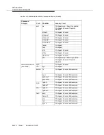
Page 927: ...OC 48 FT 2000 OC 48 OC 3 OC 3 OC 3 OC 3 OC 3 OC 3 DDM 2000 OC 3 OC 3 OC 3 OC 3 OC 3 OC 12 OC 12 OC 3 OC 3 OC 3 OC 3 OC 12 OC 12 DDM 2000 OC 12 OC 12 OC 3 OC 3 OC 3 OC 12 DDM 2000 OC 12 OC 3 OC 3 DDM 2000 OC 3 DDM 2000 OC 3 DDM 2000 OC 3 DDM 2000 OC 3 DDM 2000 OC 12 OC 3 Extension Span Optical OC 3 Configurations Network Large DDM 2000 FT 2000 17 Figure OC 3 DDM 2000 and Ring OC 12 DDM 2000 Between...

Page 928: ...363 206 295 IXL 001 38 of 25 Page 1997 December 1 Issue Span Optical OC 3 IS 3 Configurations Network Large DDM 2000 FT 2000 18 Figure OC 48 FT 2000 and Ring OC 12 DDM 2000 Between Extension ...
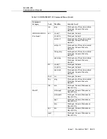
Page 929: ...48 FT 2000 OC 48 OC 3 OC 3 OC 3 OC 3 OC 3 OC 3 DDM 2000 OC 3 OC 3 OC 3 OC 3 OC 3 OC 12 OC 12 OC 3 OC 3 OC 3 OC 3 OC 12 OC 12 DDM 2000 OC 12 OC 12 OC 3 OC 3 OC 3 OC 12 DDM 2000 OC 12 OC 3 OC 3 DDM 2000 OC 3 DDM 2000 OC 3 DDM 2000 OC 3 DDM 2000 OC 12 OC 3 DDM 2000 OC 3 Span Optical OC 3 IS 3 Configurations Network Large DDM 2000 FT 2000 19 Figure OC 48 FT 2000 and Ring OC 12 DDM 2000 Between Extensi...

Page 930: ...363 206 295 IXL 001 38 of 27 Page 1997 December 1 Issue Ring Dual OC 3 IS 3 Configurations Network Large DDM 2000 FT 2000 20 Figure OC 48 FT 2000 and Ring OC 3 DDM 2000 Between Interworking ...

Page 931: ... 48 FT 2000 OC 48 OC 3 OC 3 OC 3 OC 3 OC 3 OC 3 DDM 2000 OC 3 OC 3 OC 3 OC 3 OC 3 OC 12 OC 12 OC 3 OC 3 OC 3 OC 3 OC 12 OC 12 DDM 2000 OC 12 OC 12 OC 3 OC 3 OC 3 OC 12 DDM 2000 OC 12 OC 3 OC 3 DDM 2000 OC 3 DDM 2000 OC 3 DDM 2000 OC 3 DDM 2000 OC 12 OC 3 DDM 2000 OC 3 Ring Dual OC 3 IS 3 Configurations Network Large DDM 2000 FT 2000 21 Figure OC 48 FT 2000 and Ring OC 3 DDM 2000 Between Interworki...

Page 932: ...363 206 295 IXL 001 38 of 29 Page 1997 December 1 Issue Access OC 12 Single Homed Configurations Network Large DDM 2000 FT 2000 22 Figure Ring Backbone OC 48 FT 2000 via ...

Page 933: ...8 OC 48 OC 48 FT 2000 OC 48 OC 3 OC 3 OC 3 OC 3 OC 3 OC 3 DDM 2000 OC 3 OC 3 OC 3 OC 3 OC 3 OC 12 OC 12 OC 3 OC 3 OC 3 OC 3 OC 12 OC 12 DDM 2000 OC 12 OC 12 OC 3 OC 3 OC 3 OC 12 DDM 2000 OC 12 OC 3 OC 3 DDM 2000 OC 3 DDM 2000 OC 3 DDM 2000 OC 3 DDM 2000 OC 12 OC 3 DDM 2000 OC 3 Access OC 12 Single Homed Configurations Network Large DDM 2000 FT 2000 23 Figure Ring Backbone OC 48 FT 2000 via ...

Page 934: ...363 206 295 IXL 001 38 of 31 Page 1997 December 1 Issue Access OC 3 Single Homed Configurations Network Large DDM 2000 FT 2000 24 Figure Ring Backbone OC 12 DDM 2000 via ...

Page 935: ...8 OC 48 OC 48 FT 2000 OC 48 OC 3 OC 3 OC 3 OC 3 OC 3 OC 3 DDM 2000 OC 3 OC 3 OC 3 OC 3 OC 3 OC 12 OC 12 OC 3 OC 3 OC 3 OC 3 OC 12 OC 12 DDM 2000 OC 12 OC 12 OC 3 OC 3 OC 3 OC 12 DDM 2000 OC 12 OC 3 OC 3 DDM 2000 OC 3 DDM 2000 OC 3 DDM 2000 OC 3 DDM 2000 OC 12 OC 3 DDM 2000 OC 3 Access OC 3 Single Homed Configurations Network Large DDM 2000 FT 2000 25 Figure Ring Backbone OC 12 DDM 2000 via ...

Page 936: ...363 206 295 IXL 001 38 of 33 Page 1997 December 1 Issue Access OC 3 Dual Homed Configurations Network Large DDM 2000 FT 2000 26 Figure Ring Backbone OC 48 FT 2000 via ...

Page 937: ...48 OC 48 OC 48 FT 2000 OC 48 OC 3 OC 3 OC 3 OC 3 OC 3 OC 3 DDM 2000 OC 3 OC 3 OC 3 OC 3 OC 3 OC 12 OC 12 OC 3 OC 3 OC 3 OC 3 OC 12 OC 12 DDM 2000 OC 12 OC 12 OC 3 OC 3 OC 3 OC 12 DDM 2000 OC 12 OC 3 OC 3 DDM 2000 OC 3 DDM 2000 OC 3 DDM 2000 OC 3 DDM 2000 OC 12 OC 3 DDM 2000 OC 3 Access OC 3 Dual Homed Configurations Network Large DDM 2000 FT 2000 27 Figure Ring Backbone OC 48 FT 2000 via ...

Page 938: ...363 206 295 IXL 001 38 of 35 Page 1997 December 1 Issue Access OC 12 Dual Homed Configurations Network Large DDM 2000 FT 2000 28 Figure Ring Backbone OC 48 FT 2000 via ...

Page 939: ...48 OC 48 OC 48 FT 2000 OC 48 OC 3 OC 3 OC 3 OC 3 OC 3 OC 3 DDM 2000 OC 3 OC 3 OC 3 OC 3 OC 3 OC 12 OC 12 OC 3 OC 3 OC 3 OC 3 OC 12 OC 12 DDM 2000 OC 12 OC 12 OC 3 OC 3 OC 3 OC 12 DDM 2000 OC 12 OC 3 OC 3 DDM 2000 OC 3 DDM 2000 OC 3 DDM 2000 OC 3 DDM 2000 OC 12 OC 3 DDM 2000 OC 3 Access OC 12 Dual Homed Configurations Network Large DDM 2000 FT 2000 29 Figure Ring Backbone OC 48 FT 2000 via ...

Page 940: ...363 206 295 IXL 001 38 of 37 Page 1997 December 1 Issue Access OC 3 Dual Homed Configurations Network Large DDM 2000 FT 2000 30 Figure Ring Backbone OC 12 DDM 2000 via ...

Page 941: ...48 OC 48 OC 48 FT 2000 OC 48 OC 3 OC 3 OC 3 OC 3 OC 3 OC 3 DDM 2000 OC 3 OC 3 OC 3 OC 3 OC 3 OC 12 OC 12 OC 3 OC 3 OC 3 OC 3 OC 12 OC 12 DDM 2000 OC 12 OC 12 OC 3 OC 3 OC 3 OC 12 DDM 2000 OC 12 OC 3 OC 3 DDM 2000 OC 3 DDM 2000 OC 3 DDM 2000 OC 3 DDM 2000 OC 12 OC 3 DDM 2000 OC 3 Access OC 3 Dual Homed Configurations Network Large DDM 2000 FT 2000 31 Figure Ring Backbone OC 12 DDM 2000 via ...

Page 942: ...diation CAUTION components sensitive static contain packs circuit OC 12 DDM 2000 ground static A discharge electrostatic by damaged be can which See packs circuit the handling when worn be must strap wrist in considerations discharge electrostatic TAD 100 Clearing Trouble 1 NOTE of testing and installation hardwired all that assumes procedure This also It done been has Multiplexer OC 12 DDM 2000 u...

Page 943: ...s circuit the depress momentarily can You ACO TST office retire to button alarms 2 NOTE been has system OC 12 end to end the before alarms timing avoid To the established TGS TG3 be must switches option temporarily to set running free true is following the of either if is reference timing DS1 the but specified is timing external DS1 available yet not the but specified is mode timing Line OLIU opti...

Page 944: ... 23G 23G U or OLIU 23H 23H U 6 packs circuit DLP 535 Install 177C blanks apparatus APPBLK the in MAIN A 1 and MAIN A 2 P adequate ensure to slots shelf the through flow air controlling by cooling 7 Install OLIU 21G 21G U with required if packs circuit POWER HIGH LOW to set switches LOW 8 DLP 503 Install OLIU 21G2 U 9 required if packs circuit DLP 503 Install OLIU 21D 21D U 10 required if packs cir...

Page 945: ... a during alarm the clear To same the set are DCC the set fecom address com disable the disable to command DCC 2 NOTE on installed be should loops Optical OLIU MAIN on then and s OLIU UNITS FUNCTION s Install MAIN and OLIU UNITS FUNCTION loops optical A 23G 23G U or DLP 534 OLIU 23H 23H U B 21G 21G U 21G2 U or DLP 504 OLIU 21D 21D U 12 NOTE Use set t3 address mode cc ais no undriven any set to pre...

Page 946: ...t sys all be never should It service affect may has shelf a after only used be should It system in service an on used cross and parameters provisionable all reset to equipped been values default their to connections NOTE An values DCC inconsistent the when occur will alarm init sys all becomes fecom because executed is command the use alarm the clear To again enabled set fecom address com disable ...

Page 947: ...l back looped the using back looped test auto for available not are command 7 Release TARP test transmission DS3 EC1 back looped local Perform DLP 508 18 NOTE to connected been has DDM 2000 the that assumes procedure This required as cross connection STSX and or DSX low speed the the using back looped tests cross connect Automatic test auto 7 Release TARP for available not are command transmission...

Page 948: ...CAUTION command The init sys all be never should It service affect may has shelf a after only used be should It system in service an on used cross and parameters provisionable all reset to equipped been values default their to connections NOTE An values DCC inconsistent the when occur will alarm init sys all the use alarm the clear To executed is command set fecom address com disable DCC the disab...

Page 949: ...required as features optional Activate records office DLP 509 can you tested been have network the in shelves all After subnetwork OC 12 DDM 2000 end to end the establish 24 Rings Switched Path OC 12 DDM 2000 A NTP 020 OC 12 DDM 2000 via Access OC 3 Single Homed B Ring Backbone NTP 003 OC 12 DDM 2000 via Access OC 3 Dual Homed C Ring Backbone NTP 004 Interworking Ring Dual OC 3 IS 3 D Ring FT 2000...

Page 950: ...trostatic by damaged be electrostatic See packs circuit the handling when worn be must in considerations discharge TAD 100 Clearing Trouble 1 NOTE to refer manner indicated the in respond to fails DDM 2000 the If IXL 001 Clearing Trouble 2 NOTE have system the in shelves OC 12 DDM 2000 all that assumed is It 363 206 295 test s transmission looped the passed OC DDM 2000 TOP Manual User Service 7 Re...

Page 951: ... Verify software software ring later or 13 Release TARP with equipped 2 DLP 526 from span optical each of loss optical the Determine measurements required the making by or records office 3 4 NOTE The rtrv eqpt the retrieves command Version and Equipage Report information version and type pack circuit the lists report This of section Reports and Commands the See slots more or one for the of descrip...

Page 952: ...ring alarm the clear To same the set are DCC the set fecom address com disable the disable to command DCC for loops optical Connect OLIU UNITS FUNCTION just s installed DLP 504 6 NOTE the of parameters US Side NS User Side Network The set fecom the of end each at opposite set be must command 3 Figure see example For spans optical the Use rtrv fecom set fecom to command each at parameters Side Side...

Page 953: ...ing momentarily UPD INIT the on button SYSCTL the after TGS TG3 reinstalled are packs circuit 3 NOTE the and selected is timing external If ACTY NE lighted remains LED the after TGS TG3 the and CIT the use reinserted is pack circuit rtrv sync system the of mode operational the check to command is mode the If Holdover of instead External the that check check Also connected are references timing inc...

Page 954: ...configuration provisioned 363 206 295 of section Reports TARP Multiplexer OC 12 DDM 2000 I Manual Volume User Service 7 Release 363 206 285 and User Service 13 Release TARP Multiplexer OC 3 DDM 2000 I Manual Volume the of description a for rtrv oc3 command format the Use rtrv oc3 the obtain to command Report Provisioning Line OC 3 if verify and the Use disabled or enabled is Kbyte Sbyte set oc3 Kb...

Page 955: ...lease TARP Multiplexer OC 12 363 206 285 and 13 Release TARP Multiplexer OC 3 DDM 2000 I Manual Volume User Service the of description a for rtrv sync format command the Use rtrv sync the obtain to command Report Synchronization Sync if verify and the Use disabled or enabled is Autoreconfiguration set sync Sync the disable or enable to command required as parameter Autoreconfiguration The exist se...

Page 956: ...the on shelf OC 3 last the at OLIU 2 P FN This 2 Figure See shelf OC 12 host the on OC 12 the from starting configuration ring the establish will procedure the to continuing then node OC 3 first the to end near node host node OC 3 last the from made is connection final the until node next node OC 12 host the to back the from loop optical the remove end near the At OLIU 21G 21G U 21G2 U 21D 21D U i...

Page 957: ...o tests line end to end the for order in tested being interface optical been has it If enabled is channel DCC the for condition Default work the use disabled set fecom command shelf each at far enable to communications end the use shelf each At set fecom address com enabled to command enabled is fecom communications end far ensure the of verification and connections fiber optical Perform establish...

Page 958: ...P Multiplexer OC 3 DDM 2000 I Manual Volume User Service command the of explanation an for 824 102 144 and parameters Product 2000 Technologies Lucent Guide Interworking Operations Multi Vendor Family an for partitioning subnetwork for rules engineering the of explanation the Use ent ulsdcc l3 the designate to command NSAPAREA required as routing IS IS 2 level and field 16 NOTE The rtrv pm line di...

Page 959: ...ormed be should tests transmission Additionally service circuit established the of quality and continuity the for ready now is network access OC 3 DDM 2000 single homed The video and STS 3c EC 1 DS3 For established be to service initial 363 in procedures the use shelf OC 12 DDM 2000 a on terminations 206 295 7 Release TARP Multiplexer OC 12 DDM 2000 II TOP Volume Manual User Service services those...

Page 960: ...000 DDM 2000 DDM 2000 DDM 2000 Dual homing configuration NTP 004 DDM 2000 DDM 2000 DDM 2000 Single homing configuration NTP 003 DDM 2000 DDM 2000 linear 1 1 extension NTP 008 DDM 2000 DDM 2000 DDM 2000 DDM 2000 DDM 2000 linear 1 1 extension NTP 008 OC 3 OC 3 OC 3 OC 3 OC 3 OC 3 OC 12 OC 3 OC 3 OC 12 Configurations OC 3 OC 12 DDM 2000 DDM 2000 Example 1 Figure ...

Page 961: ...3 OC3 1 2 P TSI DDM 2000 OC 12 DDM 2000 OC 12 OC12 Node 1 MAIN B2 P 23G 23G U OLIU MAIN B1 23G 23G U OLIU A B C 21G U OLIU C B 1 1 2 P 2 P 2 P A D D 1 2 P TSI DDM 2000 OC 12 Node 2 MAIN B2 P 23G 23G U OLIU MAIN B1 23G 23G U OLIU A B C 21G U OLIU C B 1 1 2 P 2 P 2 P A D D 1 2 P TSI DDM 2000 OC 12 IN OC12 OUT Node 3 MAIN B2 P 23G 23G U OLIU MAIN B1 23G 23G U OLIU A B C 21G U OLIU C B 1 1 2 P 2 P 2 P...

Page 962: ...1 1 2 P 2 P A 1 DDM 2000 OC 3 Node 5 MAIN B1 23G 23G U OLIU MAIN B2 P 23G 23G U OLIU A B C 21G U OLIU C B 1 1 2 P 2 P A D D 1 2 P TSI US NS NS US NS US OC3 OC3 DDM 2000 OC 12 DCC Network Side NS User Side US Defaults set fecom nsus ns us FN A 1 FN A 2 FN B 1 FN B 2 FN C 1 FN C 2 FN D 1 FN D 2 21 Type OLIUs 0X1 or video NS US NS US NS US NS US 23 Type OLIUs US NS dcc mb1 dcc mb2 MAIN B 1 MAIN B 2 d...

Page 963: ...atic See packs circuit the handling when worn be must in considerations discharge TAD 100 Clearing Trouble 1 NOTE to refer manner indicated the in respond to fails DDM 2000 the If IXL 001 Clearing Trouble 2 NOTE have system the in shelves OC 12 DDM 2000 all that assumed is It 363 206 295 test s transmission looped the passed OC DDM 2000 TOP Manual User Service 7 Release TARP Multiplexer 12 II Volu...

Page 964: ... 12 2000 TARP with equipped is shelf OC 3 DDM 2000 the that software later or 13 Release 2 DLP 526 from span optical each of loss optical the Determine measurements required the making by or records office 3 4 NOTE The rtrv eqpt the retrieves command Version and Equipage Report information version and type pack circuit the lists report This of section Reports and Commands the See slots more or one...

Page 965: ...g alarm the clear To same the set are DCC the set fecom address com disable the disable to command DCC for loops optical Connect OLIU UNITS FUNCTION just s installed DLP 504 6 NOTE the of parameters US Side NS User Side Network The set fecom the of end each at opposite set be must command 5 and 4 Figures see example For spans optical the Use rtrv fecom set fecom to command each at parameters Side ...

Page 966: ...ing momentarily UPD INIT the on button SYSCTL the after TGS TG3 reinstalled are packs circuit 3 NOTE the and selected is timing external If ACTY NE lighted remains LED the after TGS TG3 the and CIT the use reinserted is pack circuit rtrv sync system the of mode operational the check to command is mode the If Holdover of instead External the that check check Also connected are references timing inc...

Page 967: ...configuration provisioned 363 206 295 of section Reports TARP Multiplexer OC 12 DDM 2000 I Manual Volume User Service 7 Release 363 206 285 and User Service 13 Release TARP Multiplexer OC 3 DDM 2000 I Manual Volume the of description a for rtrv oc3 command format the Use rtrv oc3 the obtain to command Report Provisioning Line OC 3 if verify and the Use disabled or enabled is Kbyte Sbyte set oc3 Kb...

Page 968: ...ARP Multiplexer OC 12 363 206 285 and 13 Release TARP Multiplexer OC 3 DDM 2000 I Volume Manual User Service the of description a for rtrv sync format command the Use rtrv sync the obtain to command Report Synchronization Sync if verify and the Use disabled or enabled is Autoreconfiguration set sync Sync the disable or enable to command required as parameter Autoreconfiguration The exist settings ...

Page 969: ...to used being when 3 Node toward directed be then will 4 Node from Traffic 2 the from traffic all that note 3 Figure In made are cross connections that positions slot the of because 8 Node to directed be will shelf OC 3 line OC 3 the terminate 2 NOTE OC 3 first the that requires configuration ring dual homed A MAIN 1 OLIU to connect OLIU 1 UNITS FUNCTION OC 12 host one on OC 3 last The shelf OLIU ...

Page 970: ...ng span optical associated the from OLIU OC 3 Figure in example for 7 Node shelf 3 OLIU MAIN 1 13 NOTE end far for used DCC channel communication data section The shelf element network each at enabled be must communications to tests line end to end the for order in tested being interface optical has it If enabled is channel DCC the for condition Default work the use disabled been set fecom command...

Page 971: ...00 Technologies Lucent Guide Interworking Operations Multi Vendor Family an for partitioning subnetwork for rules engineering the of explanation the Use ent ulsdcc l3 the designate to command NSAPAREA required as routing IS IS 2 level and field 16 NOTE The rtrv pm line displays procedure following the in command lines OC 3 the with associated data monitoring performance system the on terminated te...

Page 972: ...erformed be should tests transmission Additionally service circuit established the of quality and continuity the for ready now is network access OC 3 DDM 2000 dual homed The video and STS 3c EC 1 DS3 For established be to service initial 363 in procedures the use shelf OC 12 DDM 2000 a on terminations 206 295 7 Release TARP Multiplexer OC 12 DDM 2000 II TOP Volume Manual User Service services thos...

Page 973: ...000 DDM 2000 DDM 2000 DDM 2000 Dual homing configuration NTP 004 DDM 2000 DDM 2000 DDM 2000 Single homing configuration NTP 003 DDM 2000 DDM 2000 linear 1 1 extension NTP 008 DDM 2000 DDM 2000 DDM 2000 DDM 2000 DDM 2000 linear 1 1 extension NTP 008 OC 3 OC 3 OC 3 OC 3 OC 3 OC 3 OC 12 OC 3 OC 3 OC 12 Configurations OC 3 OC 12 DDM 2000 DDM 2000 Example 1 Figure ...

Page 974: ...1 2 P TSI OC3 OC3 1 2 P TSI DDM 2000 OC 12 DDM 2000 OC 12 OC12 Node 1 MAIN B2 P 23G 23G U OLIU MAIN B1 23G 23G U OLIU A B C 21G U OLIU C B 1 1 2 P 2 P 2 P A D D 1 2 P TSI DDM 2000 OC 12 Node 2 MAIN B2 P 23G 23G U OLIU MAIN B1 23G 23G U OLIU A B C 21G U OLIU C B 1 1 2 P 2 P 2 P A D D 1 2 P TSI DDM 2000 OC 12 IN OC12 OUT Node 3 MAIN B2 P 23G 23G U OLIU MAIN B1 23G 23G U OLIU A B C 21G U OLIU C B 1 1...

Page 975: ...MAIN B2 P 23G 23G U OLIU MAIN B1 23G 23G U OLIU A B C 21G U OLIU C B 1 1 2 P 2 P 2 P A D D 1 2 P TSI DDM 2000 OC 12 Node 2 MAIN B2 P 23G 23G U OLIU MAIN B1 23G 23G U OLIU A B C 21G U OLIU C B 1 1 2 P 2 P 2 P A D D 1 2 P TSI DDM 2000 OC 12 IN OC12 OUT Node 3 MAIN B2 P 23G 23G U OLIU MAIN B1 23G 23G U OLIU A B C 21G U OLIU C B 1 1 2 P 2 P 2 P A D D 1 2 P TSI DDM 2000 OC 12 Node 6 MAIN B2 P 23G 23G U...

Page 976: ... 23G 23G U OLIU MAIN B2 P 23G 23G U OLIU A B C 21G U OLIU C B 1 1 2 P 2 P 2 P A D D 1 2 P TSI MAIN B1 23G 23G U OLIU MAIN B2 P 23G 23G U OLIU A B C 21G U OLIU C B 1 1 2 P 2 P A D D 1 2 P TSI US NS US NS NS US NS US OC3 OC3 DDM 2000 OC 12 DCC Network Side NS User Side US Defaults set fecom nsus ns us FN A 1 FN A 2 FN B 1 FN B 2 FN C 1 FN C 2 FN D 1 FN D 2 21 Type OLIUs 0X1 or video NS US NS US NS U...

Page 977: ...21 Type OLIUs 0X1 or video NS US NS US NS US NS US 23 Type OLIUs US NS dcc mb1 dcc mb2 MAIN B 1 MAIN B 2 dcc a1 dcc a2 dcc b1 dcc b2 dcc c1 dcc c2 dcc d1 dcc d2 MAIN B1 23G 23G U OLIU MAIN B2 P 23G 23G U OLIU A B C 21G U OLIU C B 1 1 2 P 2 P 2 P A D D 1 2 P TSI US NS DDM 2000 OC 12 Node 5 MAIN B1 23G 23G U OLIU MAIN B2 P 23G 23G U OLIU A B C 21G U OLIU C B 1 1 2 P 2 P 2 P A D D 1 2 P TSI US NS DDM...

Page 978: ... TAD 100 Clearing Trouble 1 NOTE this with continuing before established be must system ring OC 12 The equipped been not have network the of nodes the all If procedure to refer installed and IXL 001 Order Turnup Circuit System for ring a establish to and shelves DDM 2000 the equip to procedures system 2 NOTE to refer manner indicated the in respond to fails DDM 2000 the If IXL 001 Clearing Trouble...

Page 979: ... used being DLP 503 for loops optical Connect OLIU UNITS FUNCTION just s installed 3 DLP 504 4 NOTE The rtrv oc3 the retrieves command Line OC 3 Report Provisioning each about information lists report This the by set attributes includes information This line OC 3 set oc3 applications The command app the of parameter set oc3 to set be must command video terminating each and CO the at manual this of...

Page 980: ...shelf OC 12 the enable to network the use for licensed service set feat feat sts3c act enabled LEDs any If activated are alarms or LEDs no that Verify to refer activated are alarms or Clearing Trouble IXL 001 trouble clearing appropriate the follow and procedure 6 from span optical each of loss optical the Determine measurements required the making by or records office 7 the of verification and co...

Page 981: ... of each at and node 2 NOTE The ent crs sts3c dlt crs sts3c and rtrv crs sts3c STS 3c retrieve and delete enter to used be may commands the See network ring protected path a in cross connections of description a for manual this of section Reports and Commands commands for cross connections STS 3c necessary the Determine each and node RT terminating each CO the order circuit or order work the from ...

Page 982: ... the in is port a If nmon n or monitored not is signal the state the to go automatically not will port The alarmed service in i the in will it as detected is signal a when state auto a the In state nmon the to returned be must port the state auto the using state set state sts3c signal of monitoring on turn to command be can port that with associated packs circuit any before and failures the by lis...

Page 983: ...C B 1 2 P A D D 1 2 P TSI 1 DDM 2000 OC 12 DDM 2000 OC 12 OC12 Node 1 MAIN B2 P 23G 23G U OLIU MAIN B1 23G 23G U OLIU A B C C B 1 2 P 2 P A D D 1 2 P TSI DDM 2000 OC 12 Node 2 MAIN B2 P 23G 23G U OLIU MAIN B1 23G 23G U OLIU A B C C B 1 1 2 P 2 P 2 P A D D 1 2 P TSI DDM 2000 OC 12 IN OC12 OUT OC12 OC 3c STS 3c 21G U OLIU 21G U OLIU Broadband Terminal 1 2 P 1 1 21G U OLIU 21G U OLIU 21G U OLIU 21G U...

Page 984: ...ctrostatic TAD 100 Clearing Trouble 1 NOTE this with continuing before established be must system ring OC 12 The equipped been not have network the of nodes the all If procedure to refer installed and IXL 001 Order Turnup Circuit System for ring a establish to and shelves DDM 2000 the equip to procedures system 2 NOTE to refer manner indicated the in respond to fails DDM 2000 the If IXL 001 Cleari...

Page 985: ... FUNCTION slots A FN B FN C FN or D FN channel STS 3c the for used being DLP 503 for loops optical Connect OLIU UNITS FUNCTION just s installed 3 DLP 504 4 NOTE The rtrv oc3 the retrieves command Line OC 3 Report Provisioning each about information lists report This the by set attributes includes information This line OC 3 set oc3 manual this of section Reports and Commands the See command the of ...

Page 986: ...for shelf OC 12 the enable to network the use for licensed set feat feat sts3c act enabled LEDs any If activated are alarms or LEDs no that Verify to refer activated are alarms or Clearing Trouble IXL 001 trouble clearing appropriate the follow and procedure 6 span optical OC 3 each of loss optical the Determine required the making by or records office from measurements 7 the of verification and c...

Page 987: ...ission the of each at and node pass through each at made are connections nodes terminating 2 NOTE The ent crs sts3c dlt crs sts3c and rtrv crs sts3c STS 3c retrieve and delete enter to used be may commands the See network ring protected path a in cross connections of description a for manual this of section Reports and Commands commands for cross connections STS 3c necessary the Determine from nod...

Page 988: ... the in is port a If nmon n or monitored not is signal the state the to go automatically not will port The alarmed service in i the in will it as detected is signal a when state auto a the In state nmon the to returned be must port the state auto the using state set state sts3c signal of monitoring on turn to command be can port that with associated packs circuit any before and failures the by lis...

Page 989: ...G U OLIU A B C C B 1 2 P A D D 1 2 P TSI 1 DDM 2000 OC 12 DDM 2000 OC 12 OC12 Node 1 MAIN B2 P 23G 23G U OLIU MAIN B1 23G 23G U OLIU A B C C B 1 2 P 2 P A D D 1 2 P TSI DDM 2000 OC 12 Node 2 MAIN B2 P 23G 23G U OLIU MAIN B1 23G 23G U OLIU A B C C B 1 1 2 P 2 P 2 P A D D 1 2 P TSI DDM 2000 OC 12 IN OC12 OUT OC12 OC 3c STS 3c 21G U OLIU 21G U OLIU STS 3c OC 3c Source 1 2 P 1 1 21G U OLIU 21G U OLIU ...

Page 990: ...ischarge electrostatic by damaged be electrostatic See packs circuit the handling when worn be must in considerations discharge TAD 100 Clearing Trouble 1 NOTE service in is ring OC 12 DDM 2000 the that assumes procedure This OC 12 this between added being is span optical OC 3 IS 3 new a and 2 and 1 Figures See FT 2000 and ring 2 NOTE to refer manner indicated the in respond to fails DDM 2000 the ...

Page 991: ...ur may damage Eye beam the to exposure direct Avoid instruments optical NOTE The rtrv eqpt the retrieves command Version and Equipage Report information version and type pack circuit the lists report This of section Reports and Commands the See slots more or one for the of description a for manual this rtrv eqpt format command verify install node OC 12 At 21G 21G U 21G2 OLIU U 21D 21D U in packs c...

Page 992: ...com disable the disable to command DCC for loops optical Connect OLIU UNITS FUNCTION installed just s 5 NOTE The rtrv oc3 the retrieves command Line OC 3 Report Provisioning each about information lists report This the by set attributes includes information This line OC 3 IS 3 set oc3 applications The command app the of parameter set oc3 to set be must command 1 1 the for UNITS FUNCTION slots Repo...

Page 993: ...end each the Use rtrv fecom set fecom the at command the or DDM 2000 CONFIGURATION Enter Assignment DCC verify set to FT 2000 the at command of end each at parameters Side Side User Network established being span optical If OLIU 21G 21G U each on switch option set used are s OLIU 21G 21G U optical the of loss the with agree to facility 8 DLP 510 9 NOTE by performed be must update an changed is set...

Page 994: ... low FT 2000 the Verify Provision to Parameter OC 3 from Mode Protection 1 1 both if to or extension the for used are slots 0X1 slot one only if used is 10 the use shelf DDM 2000 At set fecom address com enabled to command enabled is fecom communications DCC end far ensure extension optical OC 3 IS 3 new the on the use shelf FT 2000 At End SECURITY Set Far Communications DCC end far ensure to comm...

Page 995: ...ress Area L3 the CONFIGURATION Set ULSDCC L3 365 575 See set be command 103 8 1 and 8 0 Releases System Lightwave OC 48 FT 2000 Manual User Service parameters command the of explanation an for 824 102 144 See Multi Family Product 2000 Technologies Lucent Guide Interworking Operations Vendor the of explanation an for partitioning subnetwork for rules engineering the use shelf DDM 2000 the At ent ul...

Page 996: ...e that requires service Establishing type the for pack s circuit correct the with equipped properly be node cross numerous requires also It established being service of required the of path the representing nodes the of each in connections verify to performed be should tests transmission Additionally service circuit established the of quality and continuity the For established be to service for re...

Page 997: ...FT 2000 FT 2000 FT 2000 DDM 2000 DDM 2000 DDM 2000 Dual homing configuration NTP 027 DDM 2000 DDM 2000 DDM 2000 Single homing configuration NTP 015 DDM 2000 DDM 2000 DDM 2000 DDM 2000 DDM 2000 linear 1 1 extension NTP 007 OC 3 OC 12 OC 12 OC 12 OC 12 OC 48 OC 12 OC 12 OC 48 Configurations OC 12 OC 48 DDM 2000 FT 2000 Example 1 Figure ...

Page 998: ...3G U OLIU MAIN B2 P 23G 23G U OLIU A B C C B 1 1 2 P 2 P A D D 1 2 P TSI 1 DDM 2000 OC 12 DDM 2000 OC 12 OC12 OC12 1A 2A 3A 2B 1B TRMTR RCVR TRMTR RCVR 7B 8A 8B 3 LS INTFC FT 2000 OC 48 OC48 OC48 OC3 IS 3 1 1 1 1 OLIU OLIU 21G U OLIU 21G U OLIU 1 2 P NS US DDM 2000 OC 12 DCC Network Side NS User Side US Defaults set fecom nsus ns us FN A FN B FN C FN D NS NS NS dcc a dcc b dcc c dcc d NS 21 Type O...

Page 999: ...n other procedures exposure radiation CAUTION can which components sensitive static contain packs circuit DDM 2000 strap wrist ground static A discharge electrostatic by damaged be electrostatic See packs circuit the handling when worn be must in considerations discharge TAD 100 Clearing Trouble 1 NOTE service in is ring OC 12 DDM 2000 the that assumes procedure This ring OC 12 this between added ...

Page 1000: ... 21G U 21G2 OLIU U 21D 21D U in packs circuit UNITS FUNCTION slots A FN B FN C FN or D FN the for used being extension OC 3 IS 3 new DLP 503 4 1 NOTE If OLIU 21G 21G U the used are packs circuit POWER HIGH LOW to set be must switch LOW loops optical the connecting before 2 NOTE an enabled is fecom If values DCC inconsistent will alarm the when occur OLIU occurs alarm the Normally back looped are s...

Page 1001: ...for used being slots 363 206 295 of section Reports and Commands the DDM 2000 I Manual Volume User Service 7 Release TARP Multiplexer OC 12 the of description a for rtrv oc3 format command the Use rtrv oc3 set oc3 OC 12 the at command to parameter applications the verify set to shelf 1 1 example For set oc3 fn a b c d all app 1 1 6 NOTE the through connected be must shelves OC 3 DDM 2000 MAIN or C...

Page 1002: ...n 363 206 285 use TARP Multiplexer OC 3 DDM 2000 II TOP Volume Manual User Service 13 Release NTP 002 Turnup System 363 206 295 in procedure or 7 Release TARP Multiplexer OC 12 DDM 2000 II Volume TOP Manual User Service System NTP 006 Turnup STS 3c OC 3c IS 3c establish to service from facility optical the of loss optical the Determine measurements required the making by or records office 7 8 NOTE...

Page 1003: ...rmed be must update an changed is setting switch option If the depressing momentarily UPD INIT the on button SYSCTL the after OLIU reinstalled is Reinstall OLIU depress momentarily and removed if s the UPD INIT the on button SYSCTL the use or UPD command Use set fecom address com enabled command OC 3 IS 3 new the on communications DCC enable to extension optical 11 and connections fiber optical OC...

Page 1004: ...mand 363 206 295 in Reports and Commands 11 OC 12 DDM 2000 I Manual Volume User Service 7 Release TARP Multiplexer and 363 206 285 13 Release TARP Multiplexer OC 3 DDM 2000 I Manual Volume User Service command the of explanation an for 824 102 144 and parameters Product 2000 Technologies Lucent Guide Interworking Operations Multi Vendor Family an for partitioning subnetwork for rules engineering t...

Page 1005: ...3 the displays report This and Commands the See lines OC 3 IS 3 of configuration provisioned 363 206 285 of section Reports TARP Multiplexer OC 3 DDM 2000 I Manual Volume User Service 13 Release 363 206 295 and User Service 7 Release TARP Multiplexer OC 12 DDM 2000 I Manual Volume the of description a for rtrv oc3 command format the Use rtrv oc3 the obtain to command Report Provisioning Line OC 3 ...

Page 1006: ...eport operational and provisioning the displays report This See DDM 2000 the of attributes synchronization the on information 363 206 285 of section Reports and Commands the DDM 2000 I Manual Volume User Service 13 Release TARP Multiplexer OC 3 363 206 295 and 7 Release TARP Multiplexer OC 12 DDM 2000 I Manual Volume User Service the of description a for rtrv sync format command the Use rtrv sync ...

Page 1007: ...h for test transmission DS1 end to end Perform 363 206 285 Use required if group speed DDM 2000 User Service 13 Release TARP Multiplexer OC 3 II TOP Volume Manual Procedures Level Detailed DLP 510 18 low each for test transmission DS3 end to end Perform required if group speed 19 DLP 508 Use established be to service for ready is network The 363 206 285 both from procedures OC 3 DDM 2000 Manual Us...

Page 1008: ...000 DDM 2000 DDM 2000 DDM 2000 Dual homing configuration NTP 004 DDM 2000 DDM 2000 DDM 2000 Single homing configuration NTP 003 DDM 2000 DDM 2000 linear 1 1 extension NTP 008 DDM 2000 DDM 2000 DDM 2000 DDM 2000 DDM 2000 linear 1 1 extension NTP 008 OC 3 OC 3 OC 3 OC 3 OC 3 OC 3 OC 12 OC 3 OC 3 OC 12 Configurations OC 3 OC 12 DDM 2000 DDM 2000 Example 1 Figure ...

Page 1009: ...IS 3 Optical Span MAIN FN A FN B FN C MAIN FN A FN B FN C OC 3 DDM 2000 OC 3 Linear Existing OC 12 Ring MAIN B1 MAIN B2 FN A FN B FN C FN D MAIN B1 MAIN B2 FN A FN B FN C FN D MAIN B1 MAIN B2 FN A FN B FN C FN D MAIN B1 MAIN B2 FN A FN B FN C FN D Ring OC 12 to Network OC 3 Linear Extension Span Optical OC 3 New Adding 2 Figure ...

Page 1010: ...N 1 FN A FN B FN C MAIN 2P DDM 2000 OC 3 Linear New OC 3 IS 3 Optical Span Existing OC 12 Ring MAIN B1 MAIN B2 FN A FN B FN C FN D MAIN B1 MAIN B2 FN A FN B FN C FN D MAIN B1 MAIN B2 FN A FN B FN C FN D MAIN B1 MAIN B2 FN A FN B FN C FN D 1 2P Ring OC 12 to Shelf OC 3 Linear Extension Span Optical OC 3 New Adding 3 Figure ...

Page 1011: ...FN A FN B FN C FN D MAIN B1 MAIN B2 FN A FN B FN C FN D MAIN B1 MAIN B2 FN A FN B FN C FN D MAIN B1 MAIN B2 FN A FN B FN C FN D Existing OC 3 Ring MAIN 1 MAIN 2 FN A FN B FN C MAIN 1 MAIN 2 FN A FN B FN C MAIN 1 MAIN 2 FN A FN B FN C MAIN 1 MAIN 2 FN A FN B FN C New OC 3 Optical Span Ring OC 12 to Ring OC 3 Extension Span Optical OC 3 New Adding 4 Figure ...

Page 1012: ...IN B2 P 23G 23G U OLIU A B C 21G U OLIU C B 1 1 2 P 2 P A D D 1 2 P TSI US NS NS US OC3 IS3 DDM 2000 OC 12 DCC Network Side NS User Side US Defaults set fecom nsus ns us FN A FN B FN C FN D NS NS NS dcc a dcc b dcc c dcc d NS 21 Type OLIUs 1 1 MAIN B1 23G 23G U OLIU MAIN B2 P 23G 23G U OLIU A B C C B 1 1 2 P 2 P 2 P A D D 1 2 P TSI US NS IN OUT DDM 2000 OC 12 Node 4 DDM 2000 OC 12 Node 1 21G U OLI...

Page 1013: ...aring Trouble NOTE CIT terminal interface craft The rtrv map network command list a including network SONET the of map a retrieve to used be may The connected are they how and network the in systems the of rtrv crs cross STS 1 retrieve to used be may command system OC 12 DDM 2000 the within connections discontinued being is span s optical which Determine the from removed been has signals service E...

Page 1014: ...sult may herein specified those than other procedures exposure radiation CAUTION interruption service a in result will connections fiber wrong of Removal span optical the for connections fiber the only remove you Ensure discontinued being NOTE alarm audible The alarms office activate will operations following The the depressing by suppressed be may ACO button all from connections fiber optical Rem...

Page 1015: ...essed is a as such object pointed small a need will You operation accidental it operate to pen ball point If OLIU momentarily removed was pack s circuit the depress UPD INIT the on button SYSCTL the use or upd internal DDM 2000 the update to command list equipment If OLIU was pack s circuit not optical connect removed to loops fiber OLIU s DLP 504 6 off go alarms all that Verify ...

Page 1016: ...strap wrist in considerations discharge electrostatic TAD 100 Clearing Trouble be to are circuits OC 3c IS 3c which Determine system on exist alarms no verify and discontinued 2 NOTE minor or major critical office activate will operation following The the depressing by suppressed be may alarm audible The alarms ACO pushbutton from signal service Remove 21G 21G U 21G2 U or OLIU 21D 21D U OC 3c IS 3...

Page 1017: ...e or upd to command nodes terminating OC 12 DDM 2000 update 3 Use set state oc3 alarm disable to command the loop or pair line OC 3 IS 3 specified the of monitoring OC 3 IS 3 OLIUs 4 or order work the From rtrv crs sts3c command being circuit for cross connections the determine the Use discontinued rtrv crs sts3c at command the obtain to network ring the in node each STS 3c Report Connect Cross 5 ...

Page 1018: ...gh at cross connection first the when occur may alarm Critical A required terminating other the when clear and deleted is node terminating the deleted is cross connection 2 NOTE retrieve and enter delete to used be may commands following The cross connections STS 3c dlt crs sts3c ent crs sts3c and rtrv crs sts3c this of section Reports and Commands the See Cross Connection See commands of descript...

Page 1019: ...tion the set app default to 0X1 for pair line OC 3 IS 3 specified the 8 9 CAUTION the use not Do set feat if feature OC 3c the disable to command of pair one than more UNITS FUNCTION the for equipped is slots sts3c feature the use necessary If set feat each at command being service STS 3c the of path the in node the disable to discontinued sts3c feature being are spans optical If off go alarms all...

Page 1020: ...re direct Avoid of performance or adjustments or controls of Use instruments hazardous in result may herein specified those than other procedures exposure radiation CAUTION can which components sensitive static contain packs circuit DDM 2000 strap wrist ground static A discharge electrostatic by damaged be electrostatic See packs circuit the handling when worn be must in considerations discharge T...

Page 1021: ...shed systems the and slots establish to 14 Step to go connections OC 3 IS 3 using configuration the establish to procedure this with continue Otherwise service new configuration DRI initial 3 NOTE from available timing external no timed line be to is ring OC 3 the If ring or system another TGS BBF2B TG3 BBF4 packs circuit timing the and system other the to connected node the in installed be must C...

Page 1022: ...r line Optical applications supported be can length span the that verify to used be must nodes interworking ring dual OC 12 DDM 2000 the At install OLIU selected in packs circuit UNITS FUNCTION slots DLP 503 nodes interworking ring dual the are shelves FT 2000 If 365 575 103 in procedures FT 2000 use OC FT 2000 8 1 and 8 0 Releases System Lightwave 48 Manual User Service Speed Low OC 3 IS 3 Add NT...

Page 1023: ...he when OHCTL the of ends both at s use loopback fiber a during alarm the clear To same the set are DCC the set fecom address com disable the disable to command DCC install nodes DDM 2000 At OLIU loops optical OC 3 DDM 2000 A DLP 505 Manual User Service OC 12 DDM 2000 B DLP 504 optical OC 3 IS 3 each of loss optical the Determine required the making by or records office from span measurements 5 fr...

Page 1024: ...d is end other the and Network which difference no makes it and same the be cannot line OC 3 the Network is end 2 NOTE far end for used DCC channel communication data section The for shelf element network each at enabled be must communications when work to tests line end to end the allowe to and communication is DDM 2000 in condition Default established is span optical the the use disabled been ha...

Page 1025: ... MAIN of nodes DRI adjacent the connecting s top the in example For ring OC 3 OC 12 DDM 2000 the between kbyte disable 1 Figure in ring OC 3 DDM 2000 2 CO MAIN 1 4 CO and MAIN 2 9 one only if nodes DRI FT 2000 At OLIU the for used is use connection DRI CONFIGURATION Set OC3 to mode protection the set to command 1 X 0 the for two If connections DRI for used slot OC 3 IS 3 OLIUs use connection DRI t...

Page 1026: ...rvice command the of explanation an for being subnetwork a of part are that shelves FT 2000 parameters and Address Area L3 the that require areas multiple into partitioned the of parameters IS 2 Level CONFIGURATION Set ULSDCC L3 365 575 103 See set be command Lightwave OC 48 FT 2000 Manual User Service 8 1 and 8 0 Releases System an for 824 102 144 See parameters command the of explanation Lucent ...

Page 1027: ...sue 9 of 8 Page LISTED ORDER IN BELOW ITEMS DO TO GO DETAILS FOR 14 nodes DRI at test line OC 3 end to end Perform DLP 552 service EC 1 or DS3 initial for ready now is network The established be to NTP 017 Turnup System DS3 NTP 023 Turnup System EC 1 15 ...

Page 1028: ... C OC 3 IS 3 OC 3 IS 3 Ring 1 Ring 2 Ring 1 Ring 2 MAIN 2 OLIU MAIN 1 OLIU A B C IN OUT IN OUT RT 1 Ring 1 Ring 2 Ring 2 Ring 1 DS1 DS3 EC 1 CO 3 CO 4 Ring 1 Ring 2 Ring 2 Ring 1 MAIN B1 OLIU MAIN B2 OLIU A C IN OUT IN OUT D MAIN B1 OLIU MAIN B2 OLIU A C IN OUT IN OUT D OC 12 path switched ring OC 3 IS 3 OC 3 IS 3 MAIN B1 OLIU MAIN B2 OLIU IN OUT IN OUT A C D MAIN B1 OLIU MAIN B2 OLIU IN OUT IN OU...

Page 1029: ... shelves OC 48 FT 2000 the of slots Speed Low the 21G 21G OLIU U 21G2 U or OC 3 s OLIU 21D 21D U in packs circuit IS 3 s the UNITS FUNCTION Existing shelves OC 12 DDM 2000 of slots STS1E LAA4 and 3STS1E BBG12 this in replaced be will packs circuit with procedure OLIU applications OC 3 IS 3 support to packs circuit used be must records office and or measurements power line Optical supported be can ...

Page 1030: ...t information more For upgrade network the execute and plan Representative Account Technologies Lucent your the Use rtrv alm alarms no that verify to command present are switches or loops locks 2 generated be will alarms that center maintenance Notify and OC 48 FT 2000 each in software Upgrade OC supports that release a with shelf OC 12 DDM 2000 later or 8 Release Ring TARP and interfaces 3 IS 3 n...

Page 1031: ... update until 2 NOTE cross all until alarm an without unequipped be cannot slots STS1E removed be must cross connections The removed are connections packs circuit removing before first 3 NOTE cross same the using be to going is pack circuit OC 3 IS 3 the If only the then removed be to is that pack circuit EC 1 the as connects where node the at those are deleted be to need that cross connects cross...

Page 1032: ...0 the At secondary node interworking ring dual FT 2000 use 1 Figure in A node example for 365 575 103 in procedures Lightwave OC 48 FT 2000 Manual User Service 8 1 and 8 0 Releases System NTP 003 Port s Speed Low EC 1 and or DS3 Delete 7 FT 2000 the At secondary node interworking ring dual 365 575 103 in procedures FT 2000 use OC FT 2000 8 1 and 8 0 Releases System Lightwave 48 Manual User Service...

Page 1033: ...sioned is end other the and Network which difference no makes it and same the be cannot line OC 3 IS 3 Network is end 2 NOTE far end for used DCC channel communication data section The for shelf element network each at enabled be must communications when work to tests line end to end the allowe to and communication is DDM 2000 in condition Default established is span optical the the use disabled b...

Page 1034: ... used slot OC 3 IS 3 OLIU two If connection DRI the for used is OLIU are s use connection DRI the for used CONFIGURATION Set OC3 to mode protection the set to command 1 1 connections DRI for used slot OC 3 IS 3 the for 11 use shelf FT 2000 the At CONFIGURATION Enter Assignment DCC channel DCC a assign to command required if connections DRI for used slot s to 12 the of verification and connections ...

Page 1035: ...TS3 Line Manual to command to node primary from tributary designated the switch See node secondary to traffic Switch node secondary 2 Figure 16 17 NOTE cross same the using be to going is pack circuit OC 3 IS 3 the If only the then removed be to is that pack circuit EC 1 the as connects where node the at those are deleted be to need that cross connects cross pass through The replaced being is pack...

Page 1036: ...ss Momentarily UPD on button SYSCTL the use or update CIT the from command 19 FT 2000 the At primary for node interworking ring dual in procedures FT 2000 use 2 Figure in B node example 365 575 103 System Lightwave OC 48 FT 2000 Manual User Service 8 1 and 8 0 Releases DS3 Delete NTP 003 Port s Speed Low EC 1 and or 20 FT 2000 the At primary use node interworking ring dual 365 575 103 in procedure...

Page 1037: ...Side ns User Side Network set 23 use shelf FT 2000 the At CONFIGURATION Set OC3 to mode protection the set to command 1 X 0 OC the for one only if connections DRI for used slot 3 IS 3 OLIU is two If connection DRI the for used OLIU for used are s use connection DRI the CONFIGURATION Set OC3 to mode protection the set to command 1 1 OC the for connections DRI for used slot 3 IS 3 24 use shelf FT 20...

Page 1038: ...2 the use node DRI OC 3 IS 3 the At ent crs sts1 or ent crs vt1 and drop proper make to commands cross connections continue 28 DLP 549 the use node primary FT 2000 At FAULT Switch Path STS3 Line Reset the switch to command primary to node secondary from tributary designated node primary to traffic Switch node 29 nodes the between connections EC 1 DS3 all Remove with STS1E LAA4 3STS1E BBG12 packs c...

Page 1039: ...TS1E OC 3 IS 3 CO 3 CO 4 Ring 1 Ring 2 Ring 2 Ring 1 MAIN B1 OLIU MAIN B2 OLIU A C IN OUT IN OUT D MAIN B1 OLIU MAIN B2 OLIU A C IN OUT IN OUT D OC 12 path switched ring OC 3 IS 3 EC 1 MAIN B1 OLIU MAIN B2 OLIU IN OUT IN OUT A C D MAIN B1 OLIU MAIN B2 OLIU IN OUT IN OUT A C D OLIU OLIU OLIU STS1E RCVR TRMTR RCVR TRMTR TRMTR RCVR CO 5 RCVR TRMTR RCVR TRMTR TRMTR RCVR CO 6 A B C D Traffic carried th...

Page 1040: ...3 IS 3 CO 3 CO 4 Ring 1 Ring 2 Ring 2 Ring 1 MAIN B1 OLIU MAIN B2 OLIU A C IN OUT IN OUT D MAIN B1 OLIU MAIN B2 OLIU A C IN OUT IN OUT D OC 12 path switched ring OC 3 IS 3 MAIN B1 OLIU MAIN B2 OLIU IN OUT IN OUT A C D MAIN B1 OLIU MAIN B2 OLIU IN OUT IN OUT A C D OLIU OLIU OLIU RCVR TRMTR RCVR TRMTR TRMTR RCVR CO 5 RCVR TRMTR RCVR TRMTR TRMTR RCVR CO 6 A B C D Traffic carried thru Secondary node O...

Page 1041: ... Applications Multiplexers OC 12 and OC 3 DDM 2000 Guide Ordering and Planning User Service this of 1 Volume and or of description a for manual OLIU applications and packs circuit Existing 3STS1E BBG12 and STS1E BBG6 be will packs circuit with procedure this in replaced OLIU OC 3 IS support to packs circuit records office and or measurements power line Optical applications 3 supported be can lengt...

Page 1042: ...contact information more For upgrade network the execute and plan Representative Account Technologies Lucent your the Use rtrv alm alarms no that verify to command present are switches or loops locks 2 generated be will alarms that center maintenance Notify shelf OC 3 OC 12 DDM 2000 each in software Upgrade and interfaces OC 3 IS 3 supports that release a with 13 Release Ring TARP OC 12 7 Release ...

Page 1043: ...ons The removed are connections packs circuit removing before first 3 NOTE cross connects same the using be to going is pack circuit OC 3 the If cross only the then removed be to is that pack circuit EC 1 the as the where node the at those are deleted be to need that connects remain can throughs pass The replaced being is pack circuit having nodes interworking ring dual of set first the At interfa...

Page 1044: ...e and D node STS1E at OC 3 the from packs circuit G node 5 depress momentarily nodes OC 3 and OC 12 both At the UPD INIT the on pushbutton SYSCTL the use or upd internal DDM 2000 the update to command list equipment 6 OC 3 the between connections EC 1 DS3 all Remove with nodes OC 12 and 3STS1E STS1E packs circuit removed 7 If OLIU 21G 21G U the set node OC 12 in installed are s the on switch optio...

Page 1045: ...f end each on terminate that elements network The opposite to set parameters Side Side User Network their have must an avoid to values values DCC inconsistent is end One alarm as provisioned is end other the and Side Network as provisioned it and same the be cannot line OC 3 the of ends Both Side User Side Network is end which difference no makes the use shelf DDM 2000 each At set fecom address co...

Page 1046: ...at Note NTP 036 using discontinued being are node DRI the or NTP 025 14 NTP 025 packs circuit having nodes interworking ring dual the At both remove replaced 3STS1E the from packs circuit both and node OC 12 STS1E OC the from packs circuit the Remove 1 Figure see example For node 3 3STS1E the and C node at OC 12 the from packs circuit STS1E H node at OC 3 the from packs circuit 15 depress momentar...

Page 1047: ...C 3 IS 3 s 19 DLP 503 the use shelf DDM 2000 each At set fecom address com enabled nsus ns us and fecom communications far end enable to command parameters us Side ns User Side Network set 20 the of verification and connections fiber optical Perform facility optical 21 DLP 551 nodes DRI at test line OC 3 IS 3 end to end Perform 1 Figure in H and C nodes between example For 22 DLP 552 the use nodes...

Page 1048: ...2 Ring 1 Ring 2 Ring 1 Ring 2 MAIN 2 OLIU MAIN 1 OLIU A B C IN OUT IN OUT RT 3 Ring 1 Ring 2 Ring 2 Ring 1 DS1 DS3 EC 1 OC 12 path switched ring MAIN B1 OLIU MAIN B2 OLIU A B C IN OUT IN OUT RT 3 D MAIN B1 OLIU MAIN B2 OLIU A B C IN OUT IN OUT RT 1 D IN OUT IN OUT MAIN B2 OLIU MAIN B1 OLIU A B C D IN OUT IN OUT MAIN B2 OLIU MAIN B1 OLIU A B C D MAIN B1 OLIU MAIN B2 OLIU A B C IN OUT IN OUT RT 2 D ...

Page 1049: ...rations discharge TAD 100 Clearing Trouble NOTE separate as configuration EC 1 DRI the treats procedure This the integrate to cross connections the use which components Ring Dual EC 1 The configuration DRI the into components the equipping first by established is configuration DRI Interworking DS3 establishing then and interfaces EC 1 the with nodes proper service establishing for procedures The n...

Page 1050: ...iation CAUTION can which components sensitive static contain packs circuit DDM 2000 strap wrist ground static A discharge electrostatic by damaged be electrostatic See packs circuit the handling when worn be must in considerations discharge TAD 100 Clearing Trouble 1 NOTE to refer manner indicated the in respond to fails DDM 2000 the If IXL 001 Clearing Trouble 2 NOTE local passed have system the ...

Page 1051: ...ts see example for configuration network the Determine 1 Figure equipped is shelf OC 48 FT 2000 host the that Verify not If software ring later or 8 Release TARP with the upgrade software later or 8 Release with equipped Verify software proper with shelf host OC 48 FT 2000 with equipped are shelves OC 12 DDM 2000 the that software ring later or 7 Release TARP 2 3 NOTE FAULT DDM the to connected ar...

Page 1052: ... 575 103 in command and 8 0 Releases System Lightwave OC 48 FT 2000 Manual User Service 8 1 Slot Speed Low Provision DLP 517 Parameters Port and 5 from span optical each of loss optical the Determine measurements required the making by or records office 6 7 1 NOTE from starting configuration ring OC 12 the establish will procedure This end near node OC 12 first the to end far node host FT 2000 the...

Page 1053: ...pecified the established is configuration this the on TGS TG3 packs circuit 2 NOTE by done be must update an changed is setting switch option the If the depressing momentarily UPD INIT the on button SYSCTL the after TGS TG3 reinstalled are packs circuit 3 NOTE the and selected is timing external If ACTY NE lighted remains LED the after TGS TG3 the and CIT the use reinserted is pack circuit rtrv sy...

Page 1054: ...his of section Reports rtrv oc12 format command the Use rtrv oc12 the obtain to command Report Provisioning Line OC 12 the Use set oc12 Kbyte Sbyte the enable to command required if parameter 10 1 NOTE be also must Kbyte Sbyte enabled is Autoreconfiguration Sync If enabled 2 NOTE in node OC 12 line timed any at enabled is Autoreconfiguration Sync If it ring a must ring a of nodes OC 12 line timed ...

Page 1055: ...ettings new 11 12 NOTE connect will that shelf DDM 2000 the enabled is reconfiguration auto If the via FT 2000 the to MAIN B 1 DDM 2000 the of first the be should to connecting shelf DDM 2000 the If FT 2000 the to connect to ring via FT 2000 MAIN B 2 P will shelf DDM 2000 the first connected is in shelves DDM 2000 subsequent othe all will as holdover in remain via FT 2000 the to connecting shelf t...

Page 1056: ...l been has it If enabled is channel DCC the for condition Default work the use disabled set fecom command shelf each at far enable to communications end the use shelf DDM 2000 each At set fecom address com enabled to command enabled is fecom communications DCC end far ensure the use shelf FT 2000 each At SECURITY Set Far Communications End end far ensure to command enabled is fecom communications ...

Page 1057: ...ress Area L3 the CONFIGURATION Set ULSDCC L3 365 575 See set be command 103 8 1 and 8 0 Releases System Lightwave OC 48 FT 2000 Manual User Service parameters command the of explanation an for 824 102 144 See Multi Family Product 2000 Technologies Lucent Guide Interworking Operations Vendor the of explanation an for partitioning subnetwork for rules engineering the use shelf DDM 2000 the At ent ul...

Page 1058: ...s requires also It established being service of required the of path the representing nodes the of each in connections verify to performed be should tests transmission Additionally service circuit established the of quality and continuity the for ready now is network access OC 12 DDM 2000 single homed The FT 2000 a on terminations service For established be to service initial to Manual User Servic...

Page 1059: ... FT 2000 FT 2000 FT 2000 DDM 2000 DDM 2000 DDM 2000 Dual homing configuration NTP 027 DDM 2000 DDM 2000 DDM 2000 Single homing configuration NTP 015 DDM 2000 DDM 2000 DDM 2000 DDM 2000 DDM 2000 linear 1 1 extension NTP 007 OC 3 OC 12 OC 12 OC 12 OC 12 OC 48 OC 12 OC 12 OC 48 Configurations OC 12 OC 48 DDM 2000 FT 2000 Example 1 Figure ...

Page 1060: ...8B 3 LS INTFC FT 2000 OC 48 OC48 OC12 OC12 OC12 US NS Node 2 MAIN B 1 MAIN B 2 P A B C C B 1 1 2 P 2 P A D D 1 2 P TSI US NS DDM 2000 OC 12 1 2 P Node 1 MAIN B 1 MAIN B 2 P A B C C B 1 1 2 P 2 P A D D 1 2 P TSI US NS DDM 2000 OC 12 1 2 P DDM 2000 OC 12 DCC Network Side NS User Side US Defaults set fecom nsus ns us 23 Type OLIUs Rings Application MAIN B 1 MAIN B 2 US NS dcc m1 dcc m2 NS NS 21 Type ...

Page 1061: ...considerations discharge TAD 100 Clearing Trouble 1 NOTE being is and service in is DDM 2000 the that assumes procedure This TARP 7 Release TARP to software 3 Release from upgraded a that requires software 7 Release SYSCTL BBG8 BBG8B a and OHCTL BCP4 be must procedure This shelf the in installed be network control same the in shelves all at locally performed 2 NOTE to refer manner indicated the in...

Page 1062: ...ly the of removal installed not are packs circuit TGS TG3 interruption service cause will pack circuit 1 NOTE 7 Release TARP a to system 3 Release a from upgrading When will operations ended single upgraded is shelf first the after system alarms major and available be not channel DCC section failed upgraded are shelves all until exist will 2 NOTE performed properly when transmission affect not wil...

Page 1063: ... verify to command TGS TG3 2 is pack circuit ACTIVE retrieve the or orders work records system From might that parameters all retrieve commands RTRV commands SET the using set been have DLP 509 manual this of section Reports and Commands the See the of description a for rtrv all Note commands the using set are that parameters the set ne and set fecom to have may parameters These commands new the a...

Page 1064: ...he depress momentarily must you ACO the and Panel User the on pushbutton SEL FE on pushbutton the SYSCTL the on countdown 10 second a start to time same the at ID FE the countdown this During etc 7 8 9 display SYSCTL may the If removed safely be SYSCTL not may countdown the failed is occur Remove SYSCTL BBG5 pack circuit Remove OHCTL BCP1 7 pack circuit Install OHCTL BCP4 8 DLP 500 9 1 NOTE after ...

Page 1065: ... password new Install SYSCTL BBG8 BBG8B DLP 501 10 NOTE the on switches by set previously were that Parameters OHCTL BCP1 and SYSCTL BBG5 new the on commands software by set are BCP4 OHCTL and SYSCTL BBG8 BBG8B controllers Shelf TID parameters NS US Side Side User Network CO RT the Use set ne and set fecom set to commands controllers new the on parameters these Shelf TID NS US Side Side User Netwo...

Page 1066: ...ave network the of nodes the all If procedure to refer installed and IXL 001 Order Turnup Circuit System for a establish to and shelves DDM 2000 the equip to procedures system 2 NOTE that assumes procedure This 3DS3 been already have packs circuit of end s terminating DS3 the at turnup shelf initial the during installed either and circuit the 3DS3 or 3STS1E been have packs circuit the of end termi...

Page 1067: ...ion a for manual this of section rtrv eqpt format command the Use rtrv eqpt the obtain to command Report Version and Equipage the that verify and required if protection and service 3DS3 packs circuit group proper in installed been have A FN B FN C FN or D FN service into put being 3 NOTE The rtrv t3 the retrieves command Provisioning Port T3 Report This port DS3 each about information lists report...

Page 1068: ... any If activated are alarms or LEDs no that Verify to refer activated are alarms or Clearing Trouble IXL 001 trouble clearing appropriate the follow and procedure 6 with equipped is nodes terminating the of one If 3STS1E DS3 support to interface EC 1 an for packs circuit low EC 1 initial establish established being services interface speed 7 NTP 023 8 1 NOTE Manual cross connections STS 1 manual ...

Page 1069: ...rovisioned 3 NOTE retrieve and enter delete to used be may commands following The network ring protected path a in cross connections STS 1 dlt crs sts1 ent crs sts1 and rtrv crs sts1 the See of description a for manual this of section Reports and Commands commands for cross connections STS 1 necessary the Determine order circuit or order work the from node each node each for cross connections STS ...

Page 1070: ...rk ring DRI a in nodes path s other the on test this repeat to path DS3 each for test transmission end to end DS3 Perform optional service into put being circuit Configuration Ring OC 12 Single A DLP 508 Configuration DRI Interworking Ring Dual B DLP 553 Configuration Ring Homing Single Dual C DLP 508 the Use set t3 of characteristics the set to command established being circuit the of port DS3 th...

Page 1071: ... alarmed service in i the in will it as detected is signal a when state auto a the In state nmon the to returned be must port the state auto the using state set state t3 failures signal of monitoring on turn to command removed be can port that with associated packs circuit any before and the by list equipment the from upd command the Use set state t3 state port the set to command established being...

Page 1072: ...st in considerations discharge TAD 100 Clearing Trouble 1 NOTE a that and service in is DDM 2000 the that assumes procedure This with equipped being is group new 3DS3 service DS3 for packs circuit that assumes also It 3STS1E the if installed been have packs circuit to refer installed been not has it If interface EC 1 an is end other IXL 001 Order Turnup Circuit System new a add to procedures for 3...

Page 1073: ... C FN J45 J42 J46 J43 and or J47 J44 or D FN J51 J48 J52 J49 and or J53 J50 cross connect DS3 the to circuit s the for point s connection equivalent or point s added being 4 LEDs any If activated are alarms or LEDs no that Verify to refer activated are alarms or Clearing Trouble IXL 001 5 6 1 NOTE Manual cross connections STS 1 manual only support releases Ring configure to shelf each at made be t...

Page 1074: ...ommands following The cross connections STS 1 retrieve dlt crs sts1 ent crs sts1 and rtrv crs sts1 of section Reports and Commands the See Cross Connection See commands of description a for manual this this of section Provisioning and Administration the in Provisioning provisioning cross connection on information more for manual for cross connections STS 1 necessary the Determine order circuit or ...

Page 1075: ...al and nodes other the on test this repeat to path DS3 STS 1 active the switch to path each for test transmission end to end DS3 Perform optional service into put being circuit Configuration Ring OC 12 Single A DLP 508 Configuration DRI Interworking Ring Dual B DLP 553 Configuration Ring Homing Single Dual C DLP 508 the Use set t3 of characteristics the set to command port DS3 the 9 the Use rtrv s...

Page 1076: ...alarmed service in i the in will it as detected is signal a when state auto a the In state nmon the to returned be must port the state auto the using state set state t3 failures signal of monitoring on turn to command removed be can port that with associated packs circuit any before and the by list equipment the from upd command the Use set state t3 state port the set to command established being ...

Page 1077: ...discontinued be to is group DS3 which Determine system the on exist alarms no verify 2 1 NOTE minor or major critical office the activate may operation following The the depressing by suppressed be may alarm audible The alarm ACO button opr aco command 2 NOTE be may service DS3 the for nodes drop terminating the of One with equipped 3STS1E for interface EC 1 an provide to packs circuit service DS3...

Page 1078: ...ng the At UPD INIT the on button SYSCTL the use or pack circuit upd Flashing list equipment the update to command FAULT off go LEDs the use available is CIT terminal interface craft a If rtrv state eqpt port right the that verify to command from changed been has in service i to auto a at state nodes terminating the 4 or order work the From rtrv crs sts1 command being circuit for cross connections ...

Page 1079: ...ed terminating other the when clear and deleted is node terminating the deleted is cross connection 2 NOTE establishing in used are rules following the configurations ring In ring each in cross connections same the from present if DRI including connections drop All 1 STS 1 all same the provisioned be must timeslot STS 1 be must ring the in nodes all rings path switched STS 1 On 2 cross connections...

Page 1080: ... DS3 the for node terminating required 7 the Remove 3DS3 3STS1E with associated packs circuit required if discontinued being group s the 8 9 NOTE the in is port a If nmon n or monitored not is signal the state the to go automatically not will port The alarmed service in i the in will it as detected is signal a when state auto a the In state nmon the to returned be must port the state auto the usin...

Page 1081: ... FOR the depress momentarily removed was pack s circuit If UPD INIT the on button SYSCTL the use or upd equipment internal DDM 2000 the update to command list was pack s circuit If not use removed set state t3 of state set to command 3DS3 3STS1E to pack circuit nmon monitored not 10 off go alarms all that Verify ...

Page 1082: ...fied those than other procedures exposure radiation CAUTION can which components sensitive static contain packs circuit DDM 2000 strap wrist ground static A discharge electrostatic by damaged be electrostatic See packs circuit the handling when worn be must in considerations discharge TAD 100 Clearing Trouble 1 NOTE to refer manner indicated the in respond to fails DDM 2000 the If IXL 001 Clearing...

Page 1083: ...3 for set probably are switches option running free end to the Before on set be must mode timing specified the established is system end the TGS TG3 packs circuit 2 NOTE by done be must update an changed is setting switch option the If the depressing momentarily UPD INIT the on button SYSCTL the after TGS TG3 reinstalled are packs circuit 3 NOTE the and selected is timing external If ACTY NE light...

Page 1084: ...ves command Report Provisioning Line OC 12 the displays report This and Commands the See lines OC 12 of configuration provisioned the of description a for manual this of section Reports rtrv oc12 format command the Use rtrv oc12 the obtain to command Report Provisioning Line OC 12 if verify and the Use disabled or enabled is Kbyte Sbyte set oc12 Kbyte Sbyte the disable or enable to command require...

Page 1085: ...of section Reports and Commands the the of rtrv sync format command the Use rtrv sync the obtain to command Report Synchronization Sync if verify and the Use disabled or enabled is Autoreconfiguration set sync Sync the disable or enable to command source sync set to and parameter Autoreconfiguration required as The exist settings TID duplicate no Verify rtrv map network the in shelf each at used b...

Page 1086: ...al ONE from loop optical the remove end near the At OLIU example for MAIN B 2 P optical the with associated the remove end other the At established being span associated the from loop optical OLIU example for MAIN B 1 established being span optical the in 8 NOTE end far for used DCC channel communication data section The shelf element network each at enabled be must communications to tests line en...

Page 1087: ...ommand 363 206 295 in Reports and Commands 11 OC 12 DDM 2000 I Manual Volume User Service 7 Release TARP Multiplexer an for 824 102 144 and parameters command the of explanation Lucent Operations Multi Vendor Family Product 2000 Technologies Guide Interworking for rules engineering the of explanation an for partitioning subnetwork the Use ent ulsdcc l3 the designate to command NSAPAREA required as...

Page 1088: ...or 2 Item from procedure this Repeat network OC 12 DDM 2000 the in established being 12 be to service initial for ready now is system The established Service DS3 Initial NTP 017 Turnup System Interface EC 1 Initial NTP 023 Turnup System Interface OC 3c STS 3c Initial NTP Turnup System 006 Interface Video Initial NTP 005 Turnup System 13 ...

Page 1089: ...2 1 2 P Node 2 MAIN B 1 MAIN B 2 P A B C C B 1 1 2 P 2 P A D D 1 2 P TSI NS US DDM 2000 OC 12 1 2 P Node 6 MAIN B 1 MAIN B 2 P A B C C B 1 1 2 P 2 P A D D 1 2 P TSI NS US DDM 2000 OC 12 1 2 P Node 3 MAIN B 1 MAIN B 2 P A B C C B 1 1 2 P 2 P A D D 1 2 P TSI NS US DDM 2000 OC 12 1 2 P DDM 2000 OC 12 DCC Network Side NS User Side US Defaults set fecom nsus ns us 23 Type OLIUs Rings Application MAIN B...

Page 1090: ...ing Trouble 1 NOTE new a and service in is DDM 2000 the that assumes procedure This Ring OC 12 Switched Path the to added being is shelf node RT 1 Figure See configuration 2 NOTE the that shelf new the on installed are loops optical that assumed is It the that and configuration looped back a in tested been has shelf new loaded been has software of release proper NTP Turnup System 002 3 NOTE compat...

Page 1091: ... 1 MAIN B 2 P MAIN B 2 P MAIN B 1 OUT IN OUT IN IN OUT OUT IN MAIN B 1 MAIN B 2 P MAIN B 2 P MAIN B 1 Node 5 Node 4 OUT IN OUT IN MAIN B 1 MAIN B 2 P Node 6 OUT IN OUT IN MAIN B 1 MAIN B 2 P Node 3 MAIN B 1 MAIN B 2 P New Node 7 m 1 m 2 m 3 m 12 TSI A B D m 1 m 2 m 3 m 12 m 1 m 2 m 3 m 12 m 1 m 2 m 3 m 12 mb 1 to mb 1 C Network Ring OC 12 Existing an to Node RT an Adding 1 Figure ...

Page 1092: ...s or loops locks 2 generated be will alarms that center maintenance Notify 3 NOTE the visualize to network the of sketch a make to helpful be may It required cross connections Use rtrv map network and rtrv map neighbor determine to commands are they how and network the in sites systems other each to connected the Use rtrv map network to site any at command exist duplicates If exist settings TID du...

Page 1093: ...cluding connections drop All 1 STS 1 all same the provisioned be must timeslot STS 1 be must ring the in nodes all rings path switched STS 1 On 2 cross connections STS 1 as provisioned 2 NOTE a in terminated be may STS 3cs 8 or OC 3s 4 DS3 EC 1s 12 to Up that terminated is DS3 EC 1 OC 3 STS 3c a Once network ring far the to ring the around directions both in reserved be must timeslot terminated is...

Page 1094: ...y on 7 1 NOTE the for enabled is messaging sync Kbyte Sbyte If MAIN B 1 and MAIN B 2 P it ring a in node any at interfaces optical must be ring the of nodes all at enabled 2 NOTE The rtrv oc12 the retrieves command Report Provisioning Line OC 12 the displays report This and Commands the See lines OC 12 of configuration provisioned the of description a for manual this of section Reports rtrv oc12 f...

Page 1095: ...ovisioning the displays report This See DDM 2000 the of attributes synchronization the on information description a for manual this of section Reports and Commands the the of rtrv sync format command the Use rtrv sync the obtain to command Report Synchronization Sync if verify and the Use disabled or enabled is Autoreconfiguration set sync Sync the disable or enable to command required as paramete...

Page 1096: ...er the condition and shelves existing connecting shelf new the to connection 10 NOTE into go to node line timed the cause will source sync main the Cutting holdover only that Verify LOS OC 12 nsa minor and AIS STS1 inc nsa cut fiber the of end each at present are alarms 11 1 NOTE but specified is mode timing external or specified is mode timing line If new the turnup shelf new at available not was...

Page 1097: ...e reinserted is pack circuit rtrv sync system the of mode operational the check to command is mode the If Holdover of instead External the that check connected are references timing incoming shelf new on mode timing Set TGS TG3 to pack circuit records office or order work in specified mode timing the DLP 510 12 NOTE the of parameters Side Side User Network The set fecom spans optical the of end ea...

Page 1098: ...n 15 DLP 511 16 NOTE multiple into partitioned being subnetwork a of part are that Shelves NSAP the that require areas AREA routing IS IS 2 level and field the of parameters ent ulsdcc l3 Section See set be command 363 206 295 in Reports and Commands 11 OC 12 DDM 2000 I Manual Volume User Service 7 Release TARP Multiplexer an for 824 102 144 and parameters command the of explanation Lucent Operati...

Page 1099: ...de adjacent the to made been have connections fiber site shelf adjacent other the from fibers optical Connect shelf new to OLIU MAIN B 2 P correct the that Ensure proper the to connected are fibers OLIU MAIN B 2 P in to node one MAIN B 1 node adjacent an in 18 DLP 511 19 NOTE connections fiber wrong indicates step this in report the If that verify connection no or fecom ON is rtrv fecom integrity ...

Page 1100: ...sts1 command 20 optical on test line optical OC 12 end to end Perform established being spans 21 DLP 548 22 NOTE to shelf each at made be must cross connections Proper DS3 EC 1 the for path end to end complete the establish has ring2 or ring1 path one After tested being port the use tested been sw path both at command path ring other the test to ends the for test transmission end to end appropriat...

Page 1101: ...D ORDER IN BELOW ITEMS DO TO GO DETAILS FOR established be to service for ready is system The Service DS3 Initial NTP 017 Turnup System Service EC 1 Initial NTP 023 Turnup System Service OC 3c STS 3c Initial NTP 005 Turnup System Service Video Initial NTP 007 Turnup System 23 ...

Page 1102: ...rn be must in considerations discharge TAD 100 Clearing Trouble NOTE CIT terminal interface craft The rtrv map network and rtrv map neighbor the of map a retrieve to used be may commands how and network the in systems the of list a including network SONET The connected are they rtrv crs sts1 used be may command OC 12 DDM 2000 the within cross connections STS 1 retrieve to system Use rtrv alm locks...

Page 1103: ...tem Interface EC 1 Discontinue NTP 025 Turnup System Service OC 3c STS 3c Discontinue Order Circuit NTP 010 Service Video Discontinue NTP 010 Order Circuit 4 5 CAUTION interruption service a in result will connections fiber wrong of Removal span optical the for connections fiber the only remove you Ensure discontinued being NOTE alarm audible The alarms office activate will operations following Th...

Page 1104: ... If with continue then procedures local per shelf the down 8 Step with continue Otherwise 10 Step 7 If OLIU are packs circuit not optical connect removed to loops fiber OLIUs 8 DLP 534 9 NOTE The UPD INIT the on pushbutton SYSCTL its prevent to recessed is a as such object pointed small a need will You operation accidental it operate to pen ball point depress momentarily removed were packs circuit...

Page 1105: ...quipped been not have network the of nodes the all If procedure this to refer installed and IXL 001 Order Turnup Circuit System for end the establish to and shelves DDM 2000 the equip to procedures network to end 2 NOTE that assumes procedure This 3STS1E low for optioned packs circuit EC 1 the at turnup shelf initial the during installed been have speed be may end s terminating other The circuit t...

Page 1106: ...ormat command the Use rtrv eqpt the obtain to command Report Version and Equipage the that verify and required if protection and service 3STS1E packs circuit group proper in installed been have A FN B FN C FN or D FN service into put being 3 NOTE The rtrv ec1 the retrieves command Port EC1 Report Provisioning each about information lists report This the by set attributes includes information This ...

Page 1107: ...reinstalled is pack circuit the set necessary If 3STS1E switch option pack circuit the reinstall and SPEED LOW to 3STS1E pack s circuit DLP 510 the Use set ec1 characteristics the set to command the of node s terminating EC 1 the at port EC 1 the of established being circuit 6 connection s cable backplane appropriate the Make FN A J33 J30 J34 J31 and or J35 J32 B FN J39 J36 J40 J37 and or J41 J38 ...

Page 1108: ... 9 10 1 NOTE Manual cross connections STS 1 manual only support releases Ring configure to shelf each at made be to have cross connections STS 1 Either established being circuit DS3 each for path transmission the cross continue and drop or cross connections drop terminating cross pass through and nodes terminating at made are connections nodes intermediate at made are connections 2 NOTE in rules f...

Page 1109: ... See commands of description a for manual this of section Provisioning and Administration the in Provisioning provisioning cross connection on information more for manual each for cross connections necessary the Determine records office or order work the from node for cross connections VT1 5 STS 1 necessary Make node each 11 Configuration Ring OC 12 A DLP 546 Configuration DRI Interworking Ring Du...

Page 1110: ...Single Dual DS3 C DLP 508 the Use rtrv state port the determine to command established being circuit the of port EC 1 the of state 13 14 NOTE the in is port a If nmon n or monitored not is signal the state the to go automatically not will port The alarmed service in i the in will it as detected is signal a when state auto a the In state nmon the to returned be must port the state auto the using st...

Page 1111: ...e electrostatic See packs circuit the handling when worn be must in considerations discharge TAD 100 Clearing Trouble 1 NOTE a that and service in is DDM 2000 the that assumes procedure This with equipped being is group new 3STS1E EC 1 an for packs circuit interface 2 NOTE to refer manner indicated the in respond to fails DDM 2000 the If IXL 001 Clearing Trouble which determine end s terminating E...

Page 1112: ...opriate the Make FN A J33 J30 J34 J31 and or J35 J32 B FN J39 J36 J40 J37 and or J41 J38 C FN J45 J42 J46 J43 and or J47 J44 or D FN J51 J48 J52 J49 and or J53 J50 cross connect EC 1 the to circuit the for point s connection equivalent or point s added being 5 LEDs any If activated are alarms or LEDs no that Verify to refer activated are alarms or Clearing Trouble IXL 001 6 with equipped are nodes...

Page 1113: ...figurations ring In ring each in cross connections establishing same the from present if DRI including connections drop All 1 STS 1 all same the provisioned be must timeslot STS 1 be must ring the in nodes all rings path switched STS 1 On 2 cross connections STS 1 as provisioned 3 NOTE and enter delete convert to used be may commands following The cross connections retrieve dlt crs sts1 ent crs st...

Page 1114: ... Homing Single Dual D DLP 554 for test transmission end to end appropriate the Perform path a in circuit a For service into put being circuit the use network ring protected sw path address terminating both at command on test this repeat and path active the switch to nodes path other the 10 Test Ring OC 12 Single DS3 A DLP 508 Test DRI Interworking Ring Dual DS3 B DLP 553 Test Homing Single Dual DS...

Page 1115: ...larmed service in i the in will it as detected is signal a when state auto a the In state nmon the to returned be must port the state auto the using state set state ec1 failures signal of monitoring on turn to command removed be can port that with associated packs circuit any before and the by list equipment the from upd command the Use set state ec1 port the set to command established being circu...

Page 1116: ...rge TAD 100 Clearing Trouble NOTE that assumes procedure This 3STS1E at installed are packs circuit either and circuit the in node terminating one 3STS1E or 3DS3 circuit It circuit the of node s terminating other the at installed are packs just not discontinued being is interface EC 1 the that assumes further see discontinued being is service DS3 If DS3 individual an System IXL 001 Order Turnup Ci...

Page 1117: ...ULT flashing begin LEDs on 3STS1E removed signals with pack circuit 3 NOTE The UPD INIT the on pushbutton SYSCTL its prevent to recessed is a as such object pointed small a need will You operation accidental it operate to pen ball point the depress momentarily nodes terminating the At UPD INIT the on button SYSCTL the use or pack circuit upd Flashing list equipment the update to command FAULT off ...

Page 1118: ...d rtrv crs sts1 at command the obtain to network ring the in node each STS 1 Report Connect Cross 6 CAUTION service interrupt may cross connections wrong Deleting 1 NOTE 3STS1E all until alarm an without unequipped be cannot slots be must cross connections The removed are cross connections the Remove packs circuit removing before first removed the remove then first nodes terminating the from cross...

Page 1119: ...he in Provisioning cross connects on information more for manual the Use dlt crs sts1 the delete to command being service all for cross connections node terminating required if removed the Use dlt crs sts1 the delete to command nonterminating each at cross connections pass through required if discontinued being service all for node 7 8 NOTE Install 177B blanks apparatus APPBLK unit function unused...

Page 1120: ... port the state auto the using state set state ec1 failures signal of monitoring on turn to command removed be can port that with associated packs circuit any before and the by list equipment the from upd command the depress momentarily removed was pack s circuit If UPD INIT the on pushbutton SYSCTL the use or upd equipment internal DDM 2000 the update to command list was pack s circuit If not use...

Page 1121: ...ge electrostatic by damaged be electrostatic See packs circuit the handling when worn be must in considerations discharge TAD 100 Clearing Trouble 1 NOTE a that and service in is DDM 2000 the that assumes procedure This EC 1 an provide to group EC 1 an to changed being is group DS3 interface 2 NOTE the in respond to fails DDM 2000 the procedure this in point any at If to refer should you manner in...

Page 1122: ... a as such object pointed small a need will You operation accidental it operate to pen ball point the On SYSCTL the depress momentarily UPD INIT button FAULT off go LEDs 5 NOTE ring OC 12 in cross connections STS 1 manual support releases Ring at made be to have cross connections STS 1 Manual applications circuit DS3 each for path transmission the configure to shelf each the at made are cross conn...

Page 1123: ...iguration the at cross connections pass through the remove then first nodes cross first the when occur may alarm Major A nodes intermediate other the when clear and deleted is node terminating the at connection deleted is cross connection terminating 2 NOTE retrieve and enter delete to used be may commands following The cross connections dlt crs sts1 ent crs sts1 and rtrv crs sts1 this of section ...

Page 1124: ...ll and jumpers option LBO out build line Set 3STS1E into packs circuit UNITS FUNCTION group A B C or D service into put being 10 DLP 547 the Use set ec1 characteristics the set to command converted being circuit the of port s EC 1 the of 11 connection s cable backplane appropriate the Make FN A J33 J30 J34 J31 and or J35 J32 B FN J39 J36 J40 J37 and or J41 J38 C FN J45 J42 J46 J43 and or J47 J44 o...

Page 1125: ...ontinue service EC 1 terminate to packs circuit to refer Otherwise 15 Step Turnup Circuit System NTP 018 Order service DS3 add to procedures for 14 each for cross connections necessary the Determine order work the from node pass through and terminating records office or 15 cross connections STS 1 necessary the change or Enter node each for 16 Configuration Ring OC 12 Single A DLP 546 Configuration...

Page 1126: ... Dual DS3 B DLP 553 Test Homing Single Dual DS3 C DLP 508 the Use rtrv state eqpt determine to command being circuit the of port s EC 1 the of state port the converted 18 19 NOTE the in is port a If nmon n or monitored not is signal the state the to go automatically not will port The alarmed service in i the in will it as detected is signal a when state auto a the In state nmon the to returned be ...

Page 1127: ...ation CAUTION can which components sensitive static contain packs circuit DDM 2000 strap wrist ground static A discharge electrostatic by damaged be electrostatic See packs circuit the handling when worn be must in considerations discharge TAD 100 Clearing Trouble 1 NOTE to refer manner indicated the in respond to fails DDM 2000 the If IXL 001 Clearing Trouble 2 NOTE local passed have system the i...

Page 1128: ...mple for configuration network the Determine 1 Figure are shelves OC 48 FT 2000 host the that Verify If software ring later or 8 Release TARP with equipped software ring later or 8 Release TARP with equipped not proper with shelves host OC 48 FT 2000 the upgrade are shelves OC 12 DDM 2000 the that Verify software software ring later or 7 Release TARP with equipped 2 3 NOTE FAULT DDM the to connect...

Page 1129: ...ave OC 48 FT 2000 Manual User Service 8 1 and 8 0 Releases Provision Parameters Port and Slot Speed Low DLP 517 4 FT 2000 to channels DCC verify assign shelf FT 2000 At See slots OC 12 speed low CONFIGURATION Enter Assignment DCC 365 575 103 in command and 8 0 Releases System Lightwave OC 48 FT 2000 Manual User Service 8 1 Slot Speed Low Provision DLP 517 Parameters Port and 5 from span optical ea...

Page 1130: ... other the to node OC 12 last the from made 2 NOTE DDM 2000 the of parameters US Side NS User Side Network The OC 12 set fecom orientation DCC FT 2000 the and command example For spans optical the of end each at opposite set be must 2 Figure see the Use rtrv fecom to DDM 2000 the at command Use parameters DCC retrieve set fecom nsus NS US DDM 2000 the at command at parameters US Side NS User Side ...

Page 1131: ...ate an changed is setting switch option the If the depressing momentarily UPD INIT the on button SYSCTL the after TGS TG3 reinstalled are packs circuit 3 NOTE the and selected is timing external If ACTY NE lighted remains LED the after TGS TG3 the and CIT the use reinserted is pack circuit rtrv sync system the of mode operational the check to command is mode the If Holdover of instead External the...

Page 1132: ...ovisioning Line OC 12 the displays report This and Commands the See lines OC 12 of configuration provisioned the of description a for manual this of section Reports rtrv oc12 format command the Use rtrv oc12 the obtain to command Report Provisioning Line OC 12 the Use set oc12 Kbyte Sbyte the enable to command required if parameter 10 1 NOTE be also must Kbyte Sbyte enabled is Autoreconfiguration ...

Page 1133: ...on set sync Sync the disable or enable to command required as parameter Autoreconfiguration The exist settings TID duplicate no Verify rtrv ne to network the in shelf each at used be may command new determine exist duplicates If settings display the use and settings set ne new make to command settings 11 12 1 NOTE connect will that shelf DDM 2000 the enabled is reconfiguration auto If the via FT 2...

Page 1134: ...ation data section The shelf element network each at enabled be must communications to tests line end to end the for order in tested being interface optical been has it If enabled is channel DCC the for condition Default work the use disabled set fecom command shelf each at far enable to communications end the use shelf DDM 2000 each At set fecom address com enabled to command enabled is fecom com...

Page 1135: ...ress Area L3 the CONFIGURATION Set ULSDCC L3 365 575 See set be command 103 8 1 and 8 0 Releases System Lightwave OC 48 FT 2000 Manual User Service parameters command the of explanation an for 824 102 144 See Multi Family Product 2000 Technologies Lucent Guide Interworking Operations Vendor the of explanation an for partitioning subnetwork for rules engineering the use shelf DDM 2000 the At ent ul...

Page 1136: ...ous requires also It established being service of required the of path the representing nodes the of each in connections verify to performed be should tests transmission Additionally service circuit established the of quality and continuity the is network access OC 12 DDM 2000 dual homed The For established be to service initial for ready now the use shelf FT 2000 a on terminations service to Manu...

Page 1137: ... FT 2000 FT 2000 FT 2000 DDM 2000 DDM 2000 DDM 2000 Dual homing configuration NTP 027 DDM 2000 DDM 2000 DDM 2000 Single homing configuration NTP 015 DDM 2000 DDM 2000 DDM 2000 DDM 2000 DDM 2000 linear 1 1 extension NTP 007 OC 3 OC 12 OC 12 OC 12 OC 12 OC 48 OC 12 OC 12 OC 48 Configurations OC 12 OC 48 DDM 2000 FT 2000 Example 1 Figure ...

Page 1138: ...FT 2000 OC 48 OLIU OLIU 1A 2A 3A 2B 1B TRMTR RCVR TRMTR RCVR 7B 8A 8B 3 LS INTFC FT 2000 OC 48 OC48 Node 2 MAIN B 1 MAIN B 2 P A B C C B 1 1 2 P 2 P A D D 1 2 P TSI US NS DDM 2000 OC 12 1 2 P Node 1 MAIN B 1 MAIN B 2 P A B C C B 1 1 2 P 2 P A D D 1 2 P TSI US NS DDM 2000 OC 12 1 2 P DDM 2000 OC 12 DCC Network Side NS User Side US Defaults set fecom nsus ns us 23 Type OLIUs Rings Application MAIN B...

Page 1139: ...lectrostatic TAD 100 Clearing Trouble 1 NOTE this with continuing before established be must system ring OC 12 The equipped been not have network the of nodes the all If procedure to refer installed and IXL 001 Order Turnup Circuit System for ring a establish to and shelves DDM 2000 the equip to procedures system 2 NOTE to refer manner indicated the in respond to fails DDM 2000 the If IXL 001 Clea...

Page 1140: ...FUNCTION slots A FN B FN C FN or D FN channel STS 3c the for used being DLP 503 for loops optical Connect OLIU UNITS FUNCTION just s installed 3 DLP 504 4 NOTE The rtrv oc3 the retrieves command Line OC 3 Report Provisioning each about information lists report This the by set attributes includes information This line OC 3 set oc3 manual this of section Reports and Commands the See command the of d...

Page 1141: ...for shelf OC 12 the enable to network the use for licensed set feat feat sts3c act enabled LEDs any If activated are alarms or LEDs no that Verify to refer activated are alarms or Clearing Trouble IXL 001 trouble clearing appropriate the follow and procedure 6 span optical OC 3 each of loss optical the Determine required the making by or records office from measurements 7 the of verification and c...

Page 1142: ...ission the of each at and node pass through each at made are connections nodes terminating 2 NOTE The ent crs sts3c dlt crs sts3c and rtrv crs sts3c STS 3c retrieve and delete enter to used be may commands the See network ring protected path a in cross connections of description a for manual this of section Reports and Commands commands for cross connections STS 3c necessary the Determine from nod...

Page 1143: ... the in is port a If nmon n or monitored not is signal the state the to go automatically not will port The alarmed service in i the in will it as detected is signal a when state auto a the In state nmon the to returned be must port the state auto the using state set state sts3c signal of monitoring on turn to command be can port that with associated packs circuit any before and failures the by lis...

Page 1144: ...NTP 028 363 206 295 Turnup System 1997 December 1 Issue 6 of 6 Page LISTED ORDER IN BELOW ITEMS DO TO GO DETAILS FOR Schematic Ring Virtual ATM Sample 1 Figure ...

Page 1145: ...Order Circuit 363 206 295 NTP 029 1 of 1 Page 1997 December 1 Issue Unused LISTED ORDER IN BELOW ITEMS DO TO GO DETAILS FOR ...

Page 1146: ...Order Circuit 363 206 295 NTP 030 1 of 1 Page 1997 December 1 Issue Unused LISTED ORDER IN BELOW ITEMS DO TO GO DETAILS FOR ...

Page 1147: ...r measurements power line supported be can length span existing the that DLP 511 2 CAUTION can which components sensitive static contain packs circuit DDM 2000 strap wrist ground static A discharge electrostatic by damaged be electrostatic See packs circuit the handling when worn be must in considerations discharge TAD 100 Clearing Trouble 1 NOTE long service of out taken be system the that requir...

Page 1148: ...trv alm alarms no that verify to command present are switches or loops locks 2 generated be will alarms that center maintenance Notify 3 NOTE The FAULT the on LED OHCTL the and flash will MJ be will LED upgraded is end other the until lighted Replace OHCTL BCP1 with pack circuit OHCTL BCP4 pack circuit DLP 518 Replace SYSCTL BBG5 with pack circuit BBG8 BBG8B SYSCTL pack circuit 4 DLP 518 with shel...

Page 1149: ... of parameters Side Side User Network The set fecom spans optical the of end each at opposite set be must command the Use rtrv fecom set fecom to command each at parameters Side Side User Network verify set established being span optical of end 8 NOTE in rules following the use should you configurations ring In ring each in cross connections establishing same the from present if DRI including conn...

Page 1150: ...ms service in for information configuration Transmission the on TGS TG3 in pack circuit TIMING for instances some In 1 slot the if upgrade this performing while or tests system during example current the with compatible not is installed being software of version the remove to necessary be may it configuration transmission TGS TG3 in pack circuit TIMING to system the force to order in 1 slot both I...

Page 1151: ...nnel required other and center maintenance Notify reconnected interrupted be will service that NOTE from fibers optical configuration ring the In MAIN A 1 node one at to connect MAIN B 1 node adjacent the at as fibers optical the reconnect and remove 1 Node At 1 Figure in shown IN OUT IN OUT Node 2 MAIN A 1 IN OUT IN OUT Node 1 MAIN B 1 MAIN A 1 MAIN B 1 Upgrade Ring to Point to Point OC 12 DDM 20...

Page 1152: ...AREA routing IS IS 2 level and field the of parameters ent ulsdcc l3 Section See set be command 363 206 295 in Reports and Commands 11 OC 12 DDM 2000 I Manual Volume User Service 7 Release TARP Multiplexer an for 824 102 144 and parameters command the of explanation Lucent Operations Multi Vendor Family Product 2000 Technologies Guide Interworking for rules engineering the of explanation an for pa...

Page 1153: ...ort This Reports and Commands the See lines OC 12 of configuration the of description a for manual this of section rtrv oc12 format command the Use rtrv oc12 the obtain to command OC 12 Report Provisioning Line if verify and the Use disabled or enabled is Kbyte Sbyte set oc12 Kbyte Sbyte the disable or enable to command required as parameter 16 1 NOTE be also must Kbyte Sbyte enabled is Autoreconf...

Page 1154: ... of attributes synchronization the on information description a for manual this of section Reports and Commands the the of rtrv sync format command the Use rtrv sync the obtain to command Report Synchronization Sync if verify and the Use disabled or enabled is Autoconfiguration set sync Sync the disable or enable to command required as parameter Autoconfiguration nodes new and complete now is conf...

Page 1155: ... be can length span existing the that DLP 511 2 CAUTION which splitter fiber Gould a using tested been has procedure This may loss of amount The span fiber the into loss of dB 3 introduces doing when considered be must and used splitter of type the for differ optical the in budget loss excess enough not is there If upgrade an the splitter a of use the allow to RT first and CO the between spans swi...

Page 1156: ...ure upgrade entire the Read actual the beginning before requirements and steps of sequence upgrade 2 NOTE the during terminal each at Reports State and LEDs faceplate Ignore be may paths transmission actual because procedure upgrade transmission the in splitter fiber of because shown those from different paths 3 NOTE the and service in is DDM 2000 the that assumes procedure This ring a to changed ...

Page 1157: ...Use rtrv alm alarms no that verify to command present are switches or loops locks 2 generated be will alarms that center maintenance Notify 3 NOTE the of parameters Side Side User Network The set fecom spans optical the of end each at opposite set be must command the Use rtrv fecom set fecom to command each at parameters Side Side User Network verify set established being span optical of end Use r...

Page 1158: ...may it configuration transmission TGS TG3 in pack circuit TIMING slot 1 to system the force to order in both If download to trying are you software the run TGS TG3 circuit only the of removal installed not are packs TGS TG3 pack circuit interruption service cause would both Ensure TGS TG3 At installed are packs circuit the use 2 Node and 1 Node switch sync s circuitpack pri manual protection the t...

Page 1159: ...and the Use line protection the to switch rtrv state eqpt main b all check to command state switch active OLIU main b 2 Figure See 1 6 use 2 Node and 1 Node At set fecom dcc mb com disabled to command fecom communications far end disable 7 Node 1 MAIN B1 IN IN MAIN B2 OUT OUT CO MAIN B1 IN IN MAIN B2 OUT OUT Node 1 Node 2 Upgrade Ring to Network Point to Point OC 12 DDM 2000 1 Figure ...

Page 1160: ...N BELOW ITEMS DO TO GO DETAILS FOR in splitter optical install 1 Node At OUT MAIN B 1 optical 2 Figure in shown as line 8 Node 1 MAIN B1 IN IN MAIN B2 OUT OUT CO MAIN B1 IN IN MAIN B2 OUT OUT Node 1 Node 2 Optical splitter Upgrade Ring to Network Point to Point OC 12 DDM 2000 2 Figure ...

Page 1161: ...on LED MAIN attempting before extinguishes OLIU switch the use only 2 Node At switch line main b pri manual to command line service the to switch active OLIU main b 1 3 Figure See Node 1 MAIN B1 IN IN MAIN B2 OUT OUT CO MAIN B1 IN IN MAIN B2 OUT OUT Node 1 Node 2 Optical splitter Upgrade Ring to Network Point to Point OC 12 DDM 2000 3 Figure ...

Page 1162: ...FOR from fiber optical remove 1 Node At MAIN B 2 OLIU OUT optical the of output other the to it connect and 4 Figure See splitter 10 Node 1 MAIN B1 IN IN MAIN B2 OUT OUT CO MAIN B1 IN IN MAIN B2 OUT OUT Node 1 Node 2 Optical splitter Connect Disconnect Upgrade Ring to Network Point to Point OC 12 DDM 2000 4 Figure ...

Page 1163: ...N attempting before extinguishes OLIU switch the use only 2 Node At switch line main b pri manual to command line protection the to service switch OLIU main b 2 active 5 Figure See 2 Node at Node 1 MAIN B1 IN IN MAIN B2 OUT OUT CO MAIN B1 IN IN MAIN B2 OUT OUT Node 1 Node 2 Optical splitter Upgrade Ring to Network Point to Point OC 12 DDM 2000 5 Figure ...

Page 1164: ...ing fiber the from output splitter optical the Disconnect 2 Node to IN MAIN B 1 1 Node to fiber the connect and OUT MAIN B 2 6 Figure See 12 Node 1 MAIN B1 IN IN MAIN B2 OUT OUT CO MAIN B1 IN IN MAIN B2 OUT OUT Node 1 Node 2 Optical splitter Disconnect Connect Upgrade Ring to Network Point to Point OC 12 DDM 2000 6 Figure ...

Page 1165: ...AIN attempting before extinguishes OLIU switch the use only 2 Node At switch line main b pri manual to command line service the to service switch OLIU main b 1 active 7 Figure See 2 Node at Node 1 MAIN B1 IN IN MAIN B2 OUT OUT CO MAIN B1 IN IN MAIN B2 OUT OUT Node 1 Node 2 Optical splitter Upgrade Ring to Network Point to Point OC 12 DDM 2000 7 Figure ...

Page 1166: ... TO GO DETAILS FOR from splitter optical remove 1 Node At OUT MAIN B 1 1 Node from fiber optical Connect OUT MAIN B 1 to 2 Node IN MAIN B 2 8 Figure See 14 Node 1 MAIN B1 IN IN MAIN B2 OUT OUT CO MAIN B1 IN IN MAIN B2 OUT OUT Node 1 Node 2 Upgrade Ring to Network Point to Point OC 12 DDM 2000 8 Figure ...

Page 1167: ...DETAILS FOR from fiber optical Disconnect IN MAIN B 1 and 1 Node at in splitter optical install IN MAIN B 1 as line optical 9 Figure in shown 15 Node 1 MAIN B1 IN IN MAIN B2 OUT OUT CO MAIN B1 IN IN MAIN B2 OUT OUT Node 1 Node 2 Optical splitter Upgrade Ring to Network Point to Point OC 12 DDM 2000 9 Figure ...

Page 1168: ...IN attempting before extinguishes OLIU switch the use only 1 Node At switch line main b pri manual to command line service the to service switch OLIU main b 1 active 10 Figure See 1 Node at Node 1 MAIN B1 IN IN MAIN B2 OUT OUT CO MAIN B1 IN IN MAIN B2 OUT OUT Node 1 Node 2 Optical splitter Upgrade Ring to Network Point to Point OC 12 DDM 2000 10 Figure ...

Page 1169: ... FOR 1 Node from fiber optical Disconnect IN MAIN B 2 and to output splitter optical remaining connect IN MAIN B 2 11 Figure See 17 Node 1 MAIN B1 IN IN MAIN B2 OUT OUT CO MAIN B1 IN IN MAIN B2 OUT OUT Node 1 Node 2 Optical splitter Disconnect Connect Upgrade Ring to Network Point to Point OC 12 DDM 2000 11 Figure ...

Page 1170: ...AIN attempting before extinguishes OLIU switch the use 1 Node At switch line main b pri manual to command line protection the to service switch OLIU main b 2 active 12 Figure See 1 Node at Node 1 MAIN B1 IN IN MAIN B2 OUT OUT CO MAIN B1 IN IN MAIN B2 OUT OUT Node 1 Node 2 Optical splitter Upgrade Ring to Network Point to Point OC 12 DDM 2000 12 Figure ...

Page 1171: ...output splitter optical remove 1 Node At MAIN B 1 IN 2 Node from fiber optical connect and OUT MAIN B 2 1 Node to IN MAIN B 1 13 Figure See 19 Node 1 MAIN B1 IN IN MAIN B2 OUT OUT CO MAIN B1 IN IN MAIN B2 OUT OUT Node 1 Node 2 Optical splitter Disconnect Connect Upgrade Ring to Network Point to Point OC 12 DDM 2000 13 Figure ...

Page 1172: ... MAIN attempting before extinguishes OLIU switch the use 1 Node At switch line main b pri manual to command line service the to service switch OLIU main b 1 active 14 Figure See 1 Node at Node 1 MAIN B1 IN IN MAIN B2 OUT OUT CO MAIN B1 IN IN MAIN B2 OUT OUT Node 1 Node 2 Optical splitter Upgrade Ring to Network Point to Point OC 12 DDM 2000 14 Figure ...

Page 1173: ... B 1 to 1 Node IN MAIN B 2 15 Figure See 21 22 NOTE until Wait FAULT on LED MAIN attempting before extinguishes OLIU switch the use 2 Node At switch line main b pri manual to command line protection the to service switch OLIU main b 2 active 15 Figure See 2 Node at Node 1 MAIN B1 IN IN MAIN B2 OUT OUT CO MAIN B1 IN IN MAIN B2 OUT OUT Node 1 Node 2 Upgrade Ring to Network Point to Point OC 12 DDM 2...

Page 1174: ...ed ACTIVE necessary If faceplate the on LED a perform switch tsi pri manual to command the make TSI BCP2 the in pack circuit TSI 2 the slot pack circuit active unseat 2 Node At OLIU MAIN B 1 24 remove 2 Node At TSI BCP2 the in pack circuit TSI 1 slot 25 unseat 2 Node At TGS TG3 the in pack circuit TIMING 1 slot 26 27 NOTE The FAULT the on LED OHCTL the and flash will MJ be will LED upgraded is end...

Page 1175: ...e must upgrades Software software shelf each 29 DLP 527 30 1 NOTE TSI BCP2 in pack circuit TSI 2 circuit illegal an as alarmed be will slot new the when result will hit transmission A pack TSI BCP3 circuit into inserted is pack TSI 1 slot 2 NOTE inserting before down settle to indications LED shelf 2 Node Allow new TSI BCP3 new insert 2 Node At TSI BCP3 into TSI 1 slot reseat 2 Node At OLIU MAIN B...

Page 1176: ... BCP2 from pack circuit TSI 2 slot 34 new seat 2 Node At TSI BCP3 into pack circuit TSI 2 slot 35 reseat 2 Node At OLIU MAIN B 2 36 37 NOTE of switch manual a if occur will transmission the on hit additional An the TSI necessary is pack circuit the identify 1 Node At TSI BCP2 the with pack circuit lighted ACTIVE necessary If faceplate the on LED a perform switch tsi pri manual to command the make ...

Page 1177: ...Node At TGS TG3 the in pack circuit TIMING 1 slot 40 41 NOTE The FAULT the on LED OHCTL the and flash will MJ be will LED upgraded is end other the until lighted Replace OHCTL BCP1 with pack circuit OHCTL BCP4 pack circuit DLP 518 Replace SYSCTL BBG5 with pack circuit BBG8 BBG8B SYSCTL pack circuit 42 DLP 518 software 7 Release TARP with shelf 1 Node Upgrade shelf each at locally made be must upgr...

Page 1178: ...circuit into inserted is pack TSI 1 slot 2 NOTE inserting before down settle to indications LED shelf 1 Node Allow new TSI BCP3 new insert 1 Node At TSI BCP3 into pack circuit TSI 1 slot reseat 1 Node At OLIU MAIN B 1 45 reseat 1 Node At TGS TG3 the in pack circuit TIMING 1 slot 46 47 NOTE the when result will hits transmission unidirectional Two MAIN B 2 OLIU removed is remove 1 Node At OLIU MAIN...

Page 1179: ... a of part are that Shelves NSAP the that require areas AREA routing IS IS 2 level and field the of parameters ent ulsdcc l3 Section See set be command 363 206 295 in Reports and Commands 11 OC 12 DDM 2000 I Manual Volume User Service 7 Release TARP Multiplexer an for 824 102 144 and parameters command the of explanation Lucent Operations Multi Vendor Family Product 2000 Technologies Guide Interwo...

Page 1180: ...port This Reports and Commands the See lines OC 12 of configuration the of description a for manual this of section rtrv oc12 format command the Use rtrv oc12 the obtain to command OC 12 Report Provisioning Line if verify and the Use disabled or enabled is Kbyte Sbyte set oc12 Kbyte Sbyte the disable or enable to command required as parameter 54 1 NOTE be also must Kbyte Sbyte enabled is Autorecon...

Page 1181: ...e of attributes synchronization the on information description a for manual this of section Reports and Commands the the of rtrv sync format command the Use rtrv sync the obtain to command Report Synchronization Sync if verify and the Use disabled or enabled is Autoconfiguration set sync Sync the disable or enable to command required as parameter Autoconfiguration nodes new and complete now is con...

Page 1182: ...Turnup System 363 206 295 NTP 033 1 of 1 Page 1997 December 1 Issue Unused LISTED ORDER IN BELOW ITEMS DO TO GO DETAILS FOR ...

Page 1183: ...inor With the connecting fiber The ring OC 12 existing currently a onto service OC 12 the and connected be already would site each at nodes OC 12 have must ring OC 12 The service carrying be already would ring 84 STS 1s more three least at carry to bandwidth excess enough onto over rolled be to going is network OC 3 the on service all if DS1s ring OC 12 the 3 NOTE OC 3 the for example an as ring O...

Page 1184: ...OLIU OLIU A C B IN OUT OUT IN OC 3 Node 1 FN A1 MAIN B2 OLIU IN OUT MAIN B1 OLIU OUT IN FN A2 FN B1 FN B2 FN C1 FN C2 FN D1 FN D2 OC 12 Node 1 OC 12 Node 2 FN A1 MAIN B2 OLIU IN OUT MAIN B1 OLIU OUT IN FN A2 FN B1 FN B2 FN C1 FN C2 FN D1 FN D2 OC 12 Node 3 OC 3 Node 3 MAIN 1 MAIN 2 OLIU OLIU A C B IN OUT OUT IN OC 3 Node 2 MAIN 2 MAIN 1 OLIU OLIU A C B IN OUT OUT IN 7 of 1 Upgrade Ring OC 12 to OC...

Page 1185: ...laced be will 22D U OLIU procedures following the in s 5 NOTE OC 12 the in installed be must software ring later or 7 Release TARP in installed be must software ring later or 13 Release TARP shelves shelves OC 3 the 6 NOTE in service this provide to Technologies Lucent contact also may You you help will installers Technologies Lucent Experienced upgrade contact information more For upgrade network...

Page 1186: ...e of end each at opposite set be must command the Use rtrv fecom set fecom to command each at parameters Side Side User Network verify set established being span optical of end The exist settings TID duplicate no Verify rtrv map network the in shelf each at used be may command determine exist duplicates If settings display to network the use and settings new set ne make to command settings new 4 ...

Page 1187: ... an at terminated be to are that function single homed a through cross connected be must rate signal VT1 5 the of case the In shelf OC 12 corresponding the in OLIU unit OC 3 to cross connected be may signal STS 1 same the signal its reaches signal STS 1 the until nodes OC 12 several at shelves signals VT1 5 28 of capacity single homed a with interfacing shelf OC 12 each At be to channels STS 1 the...

Page 1188: ...traffic carrying is that channel STS 1 each for made be a to cross connected been 3DS3 3STS1E or OLIU a in pack circuit UNITS FUNCTION channels STS 1 For node OC 12 the at slot pass through VT1 5 or STS 1 nodes OC 3 at terminating as manner same the in nodes OC 3 the at done are cross connections ring OC 3 normal a to channels STS 1 the determine shelf OC 12 each At the Use cross connected pass th...

Page 1189: ... network the in nodes the use network the in shelves all At set sync auto disabled sync disable to command auto reconfiguration 8 NOTE An switches DCC inconsistent the when occur will alarm shelf OC 12 OLIU alarm The enabled is fecom and back looped are s the as clear will OLIU and OC 12 the and removed are loopbacks interconnected are shelves OC 3 Use rtrv fecom the in shelf each at command use a...

Page 1190: ...posure radiation CAUTION are fibers when hit transmission a cause may switch protection A removed NOTE the around progresses and NE near end the at begins procedure This made are connections fiber optical all until ring OC 3 as designated shelf OC 12 the of location the at Starting the between pair fiber the disconnect NE near end the shelf OC 3 neighboring a and shelf OC 3 associated 1 Node at is...

Page 1191: ...IN OUT OUT IN OC 3 Node 1 FN A1 MAIN B2 OLIU IN OUT MAIN B1 OLIU OUT IN FN A2 FN B1 FN B2 FN C1 FN C2 FN D1 FN D2 OC 12 Node 1 OC 12 Node 2 FN A1 MAIN B2 OLIU IN OUT MAIN B1 OLIU OUT IN FN A2 FN B1 FN B2 FN C1 FN C2 FN D1 FN D2 OC 12 Node 3 OC 3 Node 3 MAIN 1 MAIN 2 OLIU OLIU A C B IN OUT OUT IN OC 3 Node 2 MAIN 2 MAIN 1 OLIU OLIU A C B IN OUT OUT IN NEW Fibers removed Fibers added 7 of 2 Upgrade ...

Page 1192: ...end the that assumption the and figures the remove 1 Node At OLIU 22F 22F U 22F2 U OC 3 from 1 MAIN remove 2 Node At slot 22F 22F U 22F2 U OLIU OC 3 from 2 P MAIN depress Momentarily slot UPD INIT on button SYSCTL nodes both at insert 1 Node At OLIU 22D U OC 3 into 1 MAIN At slot insert 2 Node OLIU 22D U OC 3 into 2 P MAIN slot 12 13 1 NOTE the upgrade this of portions during channels DCC multiple...

Page 1193: ... be must OC 3 2 P FN OC 12 the of slot OC 3 from connections fiber optical perform 1 Node At 1 MAIN OC 12 to slot 1 FN 3 Figure See DLP 551 14 NOTE the upgrade this of portions during channels DCC multiple to Due rtrv map network and rtrv map neighbor cannot commands OC 3 the between connections fiber optical of verification for used be completed been have connections fiber all until nodes OC 12 a...

Page 1194: ...IU OLIU A C B IN OUT OUT IN OC 3 Node 1 FN A1 MAIN B2 OLIU IN OUT MAIN B1 OLIU OUT IN FN A2 FN B1 FN B2 FN C1 FN C2 FN D1 FN D2 OC 12 Node 1 OC 12 Node 2 FN A1 MAIN B2 OLIU IN OUT MAIN B1 OLIU OUT IN FN A2 FN B1 FN B2 FN C1 FN C2 FN D1 FN D2 OC 12 Node 3 OC 3 Node 3 MAIN 1 MAIN 2 OLIU OLIU A C B IN OUT OUT IN OC 3 Node 2 MAIN 2 MAIN 1 OLIU OLIU A C B IN OUT OUT IN NEW 7 of 3 Upgrade Ring OC 12 to ...

Page 1195: ...configuration homed set oc3 fn a app 0X1 15 OC 3 between pair fiber the Disconnect 4 Figure See to fibers these use required If 3 Node and 2 Node 3 Node and 2 Node OC 12 connect 16 DLP 511 remove 2 Node At OLIU 22F 22F U 22F2 U OC 3 from 1 MAIN remove 3 Node At slot 22F 22F U 22F2 U OLIU OC 3 from 2 P MAIN depress Momentarily slot UPD INIT on button SYSCTL nodes both at 17 insert 2 Node At OLIU 22...

Page 1196: ...IN OUT OUT IN OC 3 Node 1 FN A1 MAIN B2 OLIU IN OUT MAIN B1 OLIU OUT IN FN A2 FN B1 FN B2 FN C1 FN C2 FN D1 FN D2 OC 12 Node 1 OC 12 Node 2 FN A1 MAIN B2 OLIU IN OUT MAIN B1 OLIU OUT IN FN A2 FN B1 FN B2 FN C1 FN C2 FN D1 FN D2 OC 12 Node 3 OC 3 Node 3 MAIN 1 MAIN 2 OLIU OLIU A C B IN OUT OUT IN OC 3 Node 2 MAIN 2 MAIN 1 OLIU OLIU A C B IN OUT OUT IN NEW Fibers removed Fibers added 7 of 4 Upgrade ...

Page 1197: ...ns fiber all until nodes OC 12 and network the throughout OC 3 from connections fiber optical perform 2 Node At 1 MAIN OC 12 to slot 1 FN 5 Figure See DLP 551 20 NOTE the upgrade this of portions during channels DCC multiple to Due rtrv map network and rtrv map neighbor cannot commands OC 3 the between connections fiber optical of verification for used be completed been have connections fiber all ...

Page 1198: ... IN OUT OUT IN OC 3 Node 1 FN A1 MAIN B2 OLIU IN OUT MAIN B1 OLIU OUT IN FN A2 FN B1 FN B2 FN C1 FN C2 FN D1 FN D2 OC 12 Node 1 OC 12 Node 2 FN A1 MAIN B2 OLIU IN OUT MAIN B1 OLIU OUT IN FN A2 FN B1 FN B2 FN C1 FN C2 FN D1 FN D2 OC 12 Node 3 OC 3 Node 3 MAIN 1 MAIN 2 OLIU OLIU A C B IN OUT OUT IN OC 3 Node 2 MAIN 2 MAIN 1 OLIU OLIU A C B IN OUT OUT IN NEW Fibers added Fibers added 7 of 5 Upgrade R...

Page 1199: ...ers these use required If 1 Node and 3 Node 1 Node and 3 Node OC 12 connect 21 DLP 511 remove 3 Node At OLIU 22F 22F U 22F2 U OC 3 from 1 MAIN remove 1 Node At slot 22F 22F U 22F2 U OLIU OC 3 from 2 P MAIN depress Momentarily slot UPD INIT on button SYSCTL nodes both at 22 insert 3 Node At OLIU 22D U OC 3 into 1 MAIN At slot insert 1 Node OLIU 22D U OC 3 into 2 P MAIN slot 23 ...

Page 1200: ... IN OUT OUT IN OC 3 Node 1 FN A1 MAIN B2 OLIU IN OUT MAIN B1 OLIU OUT IN FN A2 FN B1 FN B2 FN C1 FN C2 FN D1 FN D2 OC 12 Node 1 OC 12 Node 2 FN A1 MAIN B2 OLIU IN OUT MAIN B1 OLIU OUT IN FN A2 FN B1 FN B2 FN C1 FN C2 FN D1 FN D2 OC 12 Node 3 OC 3 Node 3 MAIN 1 MAIN 2 OLIU OLIU A C B IN OUT OUT IN OC 3 Node 2 MAIN 2 MAIN 1 OLIU OLIU A C B IN OUT OUT IN NEW Fibers added Fibers added 7 of 6 Upgrade R...

Page 1201: ...ns fiber all until nodes OC 12 and network the throughout OC 3 from connections fiber optical perform 3 Node At 1 MAIN OC 12 to slot 1 FN 7 Figure See DLP 551 25 NOTE the upgrade this of portions during channels DCC multiple to Due rtrv map network and rtrv map neighbor cannot commands OC 3 the between connections fiber optical of verification for used be completed been have connections fiber all ...

Page 1202: ... IN OUT OUT IN OC 3 Node 1 FN A1 MAIN B2 OLIU IN OUT MAIN B1 OLIU OUT IN FN A2 FN B1 FN B2 FN C1 FN C2 FN D1 FN D2 OC 12 Node 1 OC 12 Node 2 FN A1 MAIN B2 OLIU IN OUT MAIN B1 OLIU OUT IN FN A2 FN B1 FN B2 FN C1 FN C2 FN D1 FN D2 OC 12 Node 3 OC 3 Node 3 MAIN 1 MAIN 2 OLIU OLIU A C B IN OUT OUT IN OC 3 Node 2 MAIN 2 MAIN 1 OLIU OLIU A C B IN OUT OUT IN NEW Fibers added Fibers added 7 of 7 Upgrade R...

Page 1203: ...nc 26 27 NOTE receive to node one set to be would configuration timing simpliest The network the in nodes other all and clock BITS the from timing external possible are configurations timing Many timing loop receive to Use rtrv sync and mode timing check to command use necessary If provisioning proper for parameters set sync to provisioning timing change to command order work the on specified that...

Page 1204: ... 12 DDM 2000 I Manual Volume User Service 7 Release TARP Multiplexer and 363 206 285 13 Release TARP Multiplexer OC 3 DDM 2000 I Manual Volume User Service command the of explanation an for 824 102 144 and parameters Product 2000 Technologies Lucent Guide Interworking Operations Multi Vendor Family an for partitioning subnetwork for rules engineering the of explanation the Use ent ulsdcc l3 the de...

Page 1205: ...or Delete Edit and or DLP 541 Procedure Level Detailed Disks Floppy Diskettes Copy Backups Make and DLP 529 Procedure Level Detailed Login Remote Establish DLP 517 Procedure Level Detailed Replace Filter Fan DLP 537 Procedure Level Detailed Test Shelf Fan DLP 536 Procedure Level Detailed Remove Fuse Panel User DC 48V DLP 555 Procedure Level Detailed Identification Version Software Generic Retrieve...

Page 1206: ... LEDs Test DLP 507 Procedure Level Detailed Release OC 12 DDM 2000 Upgrade 7 Release TARP to 3 1 or 3 0 Service In System NTP 016 Procedure Clearing Non Trouble Program Software Upgrade DLP 527 Procedure Level Detailed Telemetry TBOS Parallel Local Upgrade TL1 X 25 to DLP 533 Procedure Level Detailed Timing Upgrade DLP 542 Procedure Level Detailed Procedures Only Reference Set Check Settings Optio...

Page 1207: ...tures restore and backup includes a of copy a save features These applications ring in information later a at restored be can they so parameters provisionable node s necessary if date for restore and backup provide features These Cross connections options port DS3 options port EC 1 options line OC 3 options line OC 12 and Interface User Graphical CPro 2000 the See more for guide user s on line Too...

Page 1208: ...nce TAD 100 Clear Indication ABN TAP 109 Clear Condition Brownout TAP 111 Clear Flashing Indication FAULT TAP 110 Clear CR Critical Alarm TAP 101 Clear MJ Major Alarm TAP 102 Clear MN Minor Alarm TAP 112 Clear Only ACTY NE Alarm TAP 117 Clear PMN Minor Power Alarm TAP 104 Clear Alarm Shelf Fan G8 ED 8C733 30 TAP 118 Clear Report Trouble TAP 105 Clear Upgrade Program During Trouble TAP 116 ...

Page 1209: ...dures clearing trouble The been have that technicians by used being are and node particular a to isolated site the to dispatched panel user the of inspection visual local a is maintenance of level second The alarm detailed retrieve to interface CIT a using then LEDs pack circuit and reports Procedures Analysis Trouble circuit faulty replacing involve document this in procedures analysis trouble Th...

Page 1210: ...formation contain Bulletins Failures Pack Circuit alarms system by reported and LEDs by identified are failures pack Circuit a occurs this When reports diagnostic automatic or manual by and or One failed has pack circuit a why to as made be must determination unseat to is failure a of cause the determining for step first a as recommendation pack circuit 3DS3 a if example For pack circuit suspected...

Page 1211: ...d to sure Be 2 packaging using position work static safe a at packs circuit all open possible If 3 static dissipate can that mats table and straps wrist grounded properly electricity protective their from packs circuit remove to wait possible Whenever 4 bay a into them insert to time is it until packaging antistatic pins connector or conductors components pack s circuit a touch Never 5 and top the...

Page 1212: ...rt a display to used be can command and Commands The conditions status and alarm OC 12 DDM 2000 command the of description a gives manual this of section Reports 2 NOTE The Report Status and Alarm Active automatically output is that example an is 1 Figure in shown report The in log CIT following actual the in entry one only be may There entries several shows report the in information the Note Addr...

Page 1213: ... N I M e v i t c a e d o m r e v o d l o h y t c a e n Report Status and Alarms Active of Example 1 Figure 3 NOTE a have conditions status or alarm Local Address Source the of operations or cross connection path channel port line slot local See occurred event the where etc X 25 DCC interface Addresses the Use manual this of section Reports and Commands the in rtrv alm necessary if report another g...

Page 1214: ... CRITICAL CR lighted LED AIS line OC12 inc of Failure OLIU 27 Step end far the at CRITICAL CR lighted LED FAULT LED on flashing OLIU s LOS OC3 inc LOF OC3 inc BER failed sig OC3 inc BER degrade sig OC3 inc of Failure OLIU end far or near at fiber receive of failure or TAP 121 linear 1 1 or TAP 120 ring 0X1 lines OC 3 both on failure If of failure or removal unprotected MXRVO or DS3 end far at CP 3...

Page 1215: ...STS1E pack circuit EC1 LOP STS1 inc 25 Step CRITICAL CR lighted LED cross incorrect or Incomplete end to an in provisioning connect removal unprotected network end a of failure obscure or 3DS3 3STS1E or OLIU end far the at CP AIS STS1 inc TAP 119 BER failed sig STS1 inc BER degrade sig STS1 inc of Failure OLIU far or end near at fiber receive of failure or end TAP 121 linear 1 1 or TAP 120 ring 0X...

Page 1216: ...llowed not CP changed be can message Default point alarm environmental An is input discrete miscellaneous RT at active Use rtrv attr env RT at command cause determine to using trouble Clear procedures local environmentn alarm minor External is 15 input alarm environmental cooling or power DC RT at active failed has RT in fan Use rtrv attr env RT at command cause determine to using trouble Clear pr...

Page 1217: ...trouble a Issue 7 no If procedures local using trouble Clear point cross connect STSX replace found trouble 3DS3 3STS1E end near at pack circuit Reference DLP 518 8 PROCEDURE THIS COMPLETED HAVE YOU STOP Is 9 FAULT an on LED OLIU flashing or lighted pack circuit If YES do then TAP 120 If NO with continue then 10 Step 10 NOTE protection and service the both of Failure TGS TG3 3STS1E or 3DS3 alarm C...

Page 1218: ...ircuit the remove Also available ACTIVE first LED settings switch Check rtrv sync the on command TGS TG3 circuit if check replaced been has pack circuit the If settings correct for packs replaced was pack circuit the before were they as same the are settings pack circuit companion the as same the set are switches the if check Also Reference DLP 510 correct settings switch Are 15 If YES do then TAP...

Page 1219: ...1 3DS3 s identified the with associated far end the at pack circuit OLIU the at slot or records office from pack s circuit the of location Determine near end the use rtrv crs STS1 the through back trace to commands identified the with associated cross connections OLIU slot were packs circuit the reason the determine removed are packs circuit If 22 settings switch no and reinserted be to is pack ci...

Page 1220: ... If OLIU failure a is trouble of cause likely the slot far end the of 3STS1E STS 1 identified the with associated pack circuit the of location Determine signal 3STS1E records office from pack circuit the use or rtrv crs STS 1 the through back trace to commands Replace signal STS 1 identified the with associated cross connections far end 3STS1E pack circuit Reference DLP 518 26 PROCEDURE THIS COMPL...

Page 1221: ...rt a display to used be can command and Commands The conditions status and alarm OC 12 DDM 2000 command the of description a gives manual this of section Reports 2 NOTE The Report Status and Alarm Active automatically output is that example an is 1 Figure in shown report The in log CIT following actual the in entry one only be may There entries several shows report the in information the Note Addr...

Page 1222: ...tions status or alarm Local Address Source the of operations or cross connection path channel port line slot local See occurred event the where etc X 25 DCC interface Addresses the Use manual this of section Reports and Commands the in rtrv alm necessary if report another get to command the in indication trouble the Note Description the of column Active Report Status and Alarm Major level alarm hi...

Page 1223: ...mentn mode holdover in been has System of because hours 4 than more for switch manual or fail ref timing ref timing Check eqpt of state check rtrv state eqpt holdover excessive reference timing external DS1 The shelf remote a from timing the or than greater offset frequency a has hertz 20 DS1 the Check timing external timing the or source a from obtained shelf remote error frequency MAJOR MJ LED l...

Page 1224: ...E the of failure or pack circuit 3STS1E end near the at pack circuit EC1 LOP STS1 inc 8 Step MAJOR MJ LED lighted OC 12 of Failure OLIU far at CP end AIS line OC12 inc 53 Step OC 3 of Failure OLIU end far at CP AIS line OC3 inc 53 Step cross incorrect or Incomplete end to an in provisioning connect removal unprotected network end a of failure or 3DS3 or OLIU circuit end far at pack AIS STS1 inc TA...

Page 1225: ...r MAJOR MJ lighted LED switches CP unexpected 46 Step failed eqpt communication X 25 OS the at failure report trouble Issue OS to failure communication X 25 Note Report Status and Alarm CIT the in appear also may trouble of descriptions Similar alarm no or Minor Major Critical for provisioned be May 6 NOTE a to performed being is installation program a If SYSCTL far the at the for normal is it end...

Page 1226: ...e no If trouble issue bad are signals reference timing If signals reference timing with found trouble no If signal s reference timing incoming bad of report replace references timing TGS TG3 packs circuit Reference DLP 518 12 PROCEDURE THIS COMPLETED HAVE YOU STOP 13 NOTE a to performed being is installation program a If SYSCTL far the at the for normal is it end FAULT near end the on LED OHCTL fl...

Page 1227: ... 16 PROCEDURE THIS COMPLETED HAVE YOU STOP and CIT Use 17 reset reset to command SYSCTL unplug or end near the at the reseat and SYSCTL the Is 18 FAULT the on LED OHCTL flashing still pack circuit DCC section failed channel If YES with continue then 19 Step If NO then PROCEDURE THIS COMPLETED HAVE YOU STOP and CIT use possible If 19 rlgn terminal far end the to in log to command DLP 517 the use an...

Page 1228: ... SYSCTL reseating and unseating by SYSCTL or the and CIT a using by reset If performed already not if command FAULT to refer reset a after flashing still is LED DLP 501 replace and SYSCTL an If terminal far end at OHCTL the and present is FAULT LED the after flashing still is SYSCTL the replace replaced is OHCTL DLP 518 exists still trouble if other the then and end one at first 28 PROCEDURE THIS ...

Page 1229: ...NO with continue then 36 Step the Is 36 MJ lighted still LED alarm If YES with continue then 37 Step If NO then PROCEDURE THIS COMPLETED HAVE YOU STOP the Is 37 FAULT on LED OHCTL lighted If YES with continue then 38 Step If NO to proceed then 43 Step and CIT Use 38 rtrv ne is provisioning If provisioning check to command and CIT use correct not set ne the to parameters set to command to refer cor...

Page 1230: ...he replace and or assistance technical seek packs circuit Lucent call or organization support technical local your supervisor your instructions operating local per RTAC Technologies 42 PROCEDURE THIS COMPLETED HAVE YOU STOP 43 NOTE inserted pack circuit wrong a by caused be also may alarm major A the into AUXCTL they what from different are that settings switch slot a before were TGS TG3 holdover ...

Page 1231: ...e without pack circuit the remove Also available ACTIVE first LED circuit the If settings correct for packs circuit the on settings switch Check were they as same the are settings if check replaced been has pack the set are switches the if check Also replaced was pack circuit the before pack circuit companion the as same Reference DLP 510 correct settings switch Are 50 If YES do then TAP 103 If NO...

Page 1232: ...ouble 1997 December 1 Issue 12 of 12 Page Replace 53 OLIU the with associated are that end far at s Address Source the of AIS line OC12 inc or AIS line OC3 inc message alarm Reference DLP 518 54 PROCEDURE THIS COMPLETED HAVE YOU STOP ...

Page 1233: ...ultiple A switch the when or failed have pack circuit protection associated circuit service a on occurs failure a and locked or inhibited is mode pack the Is FAULT an on LED OLIU lighted failed CP OLIU flashing or LOS OC12 inc etc If YES do then TAP 120 If NO with continue then 2 Step the Are 2 FAULT the of pack circuit protection and service a both on LEDs flashing not lighted type same failed CP...

Page 1234: ... 7 rtrv commands rtrv state eqpt to etc etc locks inhibits for mode switching check found trouble any Was 8 If YES with continue then 9 Step If NO do then TAP 108 the See place in be to etc inhibits locks for reason Determine 9 the of description a for manual this of section Reports and Commands switch the and commands rtrv alm report command the Use descriptions switch or mode switching reset to ...

Page 1235: ...ue 3 4 PROCEDURE THIS COMPLETED HAVE YOU STOP have you do configuration RT of type What 5 If Power Bulk with continue then 6 Step If Power Distributed to proceed then 8 Step AC Check trouble clear to plant power bulk your for documentation Use 6 enclosure RT at present is power AC verify and breakers circuit 7 PROCEDURE THIS COMPLETED HAVE YOU STOP use voltage AC incoming measure DMM multimeter di...

Page 1236: ...TIFIER 336A seconds 20 within clear alarm Did 16 If YES then PROCEDURE THIS COMPLETED HAVE YOU STOP If NO with continue then 17 Step another Replace 17 RECTIFIER 336A seconds 20 within clear alarm Did 18 If YES then PROCEDURE THIS COMPLETED HAVE YOU STOP If NO to proceed then 27 Step box breaker circuit AC main RT at tripped breaker circuit or blown fuse Is 19 If YES with continue then 20 Step If ...

Page 1237: ... until power maintain to source power other or batteries charged restored is 26 PROCEDURE THIS COMPLETED HAVE YOU STOP 27 NOTE be must analysis trouble and exist troubles multiple remain alarms If repeated to SD 7C118 and SD 7C117 use Shelf Power J1C182BA a have you If used is arrangement powering or shelf power another If trouble locate power locate to diagrams wiring and documentation appropriat...

Page 1238: ...ceplate on LED 3DS3 or 3STS1E flashing pack circuit inc LOS If YES to continue then 5 Step If NO to proceed then 7 Step to Refer failure signal EC 1 or DS3 incoming an be to appears There 5 TAP 110 condition failure clear and 6 PROCEDURE THIS COMPLETED HAVE YOU STOP Is 7 FAULT not lighted DDM 2000 in pack circuit any of faceplate on LED flashing failed CP If YES with continue then 8 Step If NO to ...

Page 1239: ...es no with correctly operating be to appears DDM 2000 FOUND TROUBLE NO of report Return 13 PROCEDURE THIS COMPLETED HAVE YOU STOP test LED the failed that pack circuit Replace 14 Reference DLP 518 test LED the Repeat 15 test LED the pass packs circuit all Did 16 If YES then PROCEDURE THIS COMPLETED HAVE YOU STOP If NO with continue then 17 Step 17 NOTE replaced just pack circuit the in not is Fail...

Page 1240: ...without pack circuit standby reseat and Unplug 2 ACTIVE in LED LED lighted the with pack circuit affected the as group same the available CIT Is 3 If YES with continue then 4 Step If NO to proceed then 6 Step and CIT Use 4 reset reset to command SYSCTL Is 5 FAULT lighted still pack circuit affected on LED If YES to proceed then 8 Step If NO then PROCEDURE THIS COMPLETED HAVE YOU STOP 6 NOTE reseat...

Page 1241: ... circuit affected the as group FAULT on LED the in pack circuit active the replace lighted still is pack circuit affected LED lighted the with pack circuit affected the as group same Reference DLP 518 Is 11 FAULT lighted still pack circuit affected on LED If YES with continue then 17 Step If NO then PROCEDURE THIS COMPLETED HAVE YOU STOP available CIT Is 12 If YES with continue then 13 Step If NO ...

Page 1242: ...plane in be to appears problem The swap to is this verify to way SYSCTL with pack circuit any and in packs circuit corresponding with indication diagnostic inconsistent it packs circuit the with moves problem the If DDM 2000 another stays problem the If defective is packs circuit more or one that means circuit the not but assembly entire the DDM 2000 original the with backplane printed a has DDM 2...

Page 1243: ...Clearing Trouble 363 206 295 TAP 107 1 of 1 Page 1997 December 1 Issue Unused ...

Page 1244: ...ED fail LED any Did 2 If YES do then TAP 115 If NO with continue then 3 Step available CIT Is 3 If YES to proceed then 7 Step If NO with continue then 4 Step no example for indications LED with associated trouble Is 4 ACTY NE or FE ACTY no lighted LED PMN MN MJ CR is alarm when lighted LED etc etc present If YES to proceed then 11 Step If NO with continue then 5 Step 5 NOTE reseating and Unseating...

Page 1245: ...le Is 10 If YES with continue then 11 Step If NO then PROCEDURE THIS COMPLETED HAVE YOU STOP 11 1 NOTE OC 12 DDM 2000 of wiring backplane in be may problem The swap to is this verify to way One Multiplexer SYSCTL circuit any and circuit corresponding with indication diagnostic inconsistent with pack moves problem the If Multiplexer OC 12 DDM 2000 another in packs is packs circuit more or one that ...

Page 1246: ...T Use rtrv alm See report status and alarm an get to command under manual this of section Reports and Commands RTRV ALM for with retrieved message each of description rtrv alm command group support technical regional your call assistance technical need you If manual this of front in listed number RTAC Technologies Lucent or 12 PROCEDURE THIS COMPLETED HAVE YOU STOP ...

Page 1247: ...priority higher the clear to better is It CR MJ first etc an clear not will this cases most in although ABN higher the If alarm clear to procedure this use then can you first cleared is alarm priority the ABN alarm 2 NOTE an clearing cases some In ABN priority higher a in result will alarm condition abnormal the clearing example For cleared being alarm switch mode sync manual an cause may holdover...

Page 1248: ...vent the rtrv alm another get to command report 3 NOTE entry one only shows that example an is 1 Figure in shown report The report actual the in entries several be may There the in information the Note Address Source and Description for line dashed single first the above entry entries top the for columns the in below report the in loopback DS1 abnormal example Active Report Status and Alarm t r o ...

Page 1249: ...l alarm highest the with starting abnormal the in listed Level Alarm column Use 7 opr aco required if alarms office audible active silence to command not and level alarm highest the for A Table in description trouble the Find 8 commands related the Conditions Status and Alarm ABN Abnormal A Table Commands Related Description switch forced switch inhibit switch line switch fn switch sync INH MSG AL...

Page 1250: ...ermined you Have 11 the causing ABN indication If YES to proceed then 14 Step If NO with continue then 12 Step the for reason the until done be to more nothing is There 12 ABN is condition known 13 PROCEDURE THIS COMPLETED HAVE YOU STOP The condition abnormal the clear to command appropriate the Use 14 be will command rls lpbk or switch the Is 15 ABN lighted still indicator If YES with continue th...

Page 1251: ... TAP 101 NO If with continue then 4 Step Is 4 FAULT more or one of faceplate on flashing LED 3DS3 3STS1E circuit packs If YES with continue then 5 Step If NO do then TAP 108 5 NOTE be can failure This failure signal DS3 EC 1 incoming an is There CIT a using isolated further session establish and Panel User on connector to CIT Connect Reference DLP 516 under manual this of section Reports and Comma...

Page 1252: ...ng feeders power DC 48V cause will measurement power for feeder wrong the disconnecting interruption service holder fuse at voltage Measure FA or FB than less measure voltage Does 4 DC volts 40 If YES with continue then 5 Step If NO to proceed then 7 Step 5 CAUTION the conditions brownout During SYSCTL normal suspend will will commands CIT and gererated be will alarms No operations not will logins...

Page 1253: ...he to traceable potential same the about at be should return problem correct and Find source 10 PROCEDURE THIS COMPLETED HAVE YOU STOP 11 NOTE reseating and Unseating SYSCTL a performs pack circuit reset program software the restarts which procedure reseat and Unseat SYSCTL use or pack ciruit reset not Do command press UPD INIT pushbutton cleared trouble Is 12 If YES then PROCEDURE THIS COMPLETED ...

Page 1254: ...escription a gives manual this 2 NOTE The Report Status and Alarm Active automatically output is a have conditions status or alarm Local in log CIT following Source Address where interface operations or port channel slot local the of the Use occurred event the rtrv alm another get to command report 3 NOTE entries several shows that example an is 1 Figure in shown report The report actual the in en...

Page 1255: ... M 1 b n i a m y t c a e n Report Status and Alarms Active of Example 1 Figure 3 NOTE a have conditions status or alarm Local Address Source the of operations or cross connection path channel port line slot local See occurred event the where etc X 25 DCC interface Addresses the Use manual this of section Reports and Commands the in rtrv alm necessary if report another get to command the in indicat...

Page 1256: ...ear at line protection or OC 12 TAP 121 TAP 363 206 285 OC 3 111 MN manual the support not does CP lighted LED currently cross connection s slot this for provisioned or CP Change cross change connections crs allowed not CP with associated When TG TIMING current slot TGS TG3 switch CP sync the support not do settings provisioned timing Change TGS TG3 switches pack circuit change or DLP 510 paramete...

Page 1257: ...FAULT LED on flashing TGS TG3 circuit pack AIS ref sync DS1 inc BER ref sync DS1 inc EOOF ref sync DS1 inc LOF ref sync DS1 inc LOS ref sync DS1 inc OOL ref sync DS1 inc signal ref sync incoming of Failure TGS TG3 provisioned pack circuit ESF or SF format frame wrong for 15 Step MN lighted LED FAULT LED on flashing 3DS3 LOS DS3 DSX from inc fail sig DS3 DSX from inc at removed or failed Equipment ...

Page 1258: ...Failure 3STS1E far or near at fiber receive of failure or end 13 Step MN lighted LED FAULT LED on flashing OLIU OC3 LOP STS1 inc slotaid lines OC 3 both on failure If of failure or removal unprotected MXRVO or DS3 end far at CP 363 206 285 TAP 112 line OC 3 one only on failure If of Failure OLIU end far or near at TAP 121 linear 1 1 or TAP 120 ring 0X1 lines OC 12 both on failure If of failure or ...

Page 1259: ...r reset failure end far at initialization SYSCTL Program site a from removed at failed or progress in installation end far SYSCTL or OHCTL failed Both end near at OLIU failed fibers transmit or transmitters end other with communication no 40 Step MN lighted LED FAULT LED circuit on lighted pack type CP unexpected different invalid settings Switch different or pack circuit other from pack circuit b...

Page 1260: ... may packs circuit Replacement installed is pack circuit the before set properly If settings invalid or improper for settings switch option pack circuit Check to refer found is trouble no DLP 518 the with pack circuit the replace and lighted FAULT LED the Is 9 MN Panel User the on off LED If YES then PROCEDURE THIS COMPLETED HAVE YOU STOP If NO with continue then 10 Step the Is 10 FAULT pack circu...

Page 1261: ...rt trouble issue protection on flashing not is LED If point cross connect DSX 3 STSX 3DS3 3STS1E service replace 3DS3 3STS1E pack circuit DLP 518 14 PROCEDURE THIS COMPLETED HAVE YOU STOP Check 15 TGS TG3 and coding line proper for switches option pack circuit settings format frame rtrv sync incoming check found trouble no If trouble issue bad are signals reference timing If signals reference timi...

Page 1262: ...removed was pack circuit the If pack circuit the depress momentarily and pack circuit the reinstall UPD INIT on button the SYSCTL momentarily reinserted be to not is pack circuit the If the depress UPD INIT the on button SYSCTL pack circuit the remove to inventory the from 19 PROCEDURE THIS COMPLETED HAVE YOU STOP installed Shelf Fan G8 ED 8C733 30 Is 20 If YES with continue then 21 Step If NO to ...

Page 1263: ...indicator NOTE distribution battery office check Panel User the on blown not is fuse If reset or fuse Replace breakers tripped or fuses blown for board fuse necessary if breaker Is Panel User on blown fuse 48V If YES with continue then 24 Step If NO do then TAP 113 24 NOTE fuses amp 10 are Panel User G1 ED 8C727 31 the on fuses The 406203190 COMCODE blown Replace Panel User on fuse 48V again blow ...

Page 1264: ... to time a at one removed be can packs Remove one and note above the in listed packs circuit of pair each of blown replace removed all reinstall again blow not does fuse If fuse 48V the with beginning time a at one packs circuit SYSCTL circuit any Replace blow to fuse the causes that pack DLP 518 one with again blows fuse If and packs circuit removed reinstall removed packs circuit of pair each of...

Page 1265: ...set are switches the if check Also Reference DLP 510 correct settings switch Are 33 If YES do then TAP 103 If NO with continue then 34 Step Use settings correct the to settings switch Change 34 sw sync command are settings switch If pack removing before pack circuit other to switch to list equipment the update previously were they what from changed be to the depressing momentarily by UPD INIT the ...

Page 1266: ...OTE a to performed being is installation program a If SYSCTL far the at the for normal is it end FAULT near end the on LED OHCTL flash to the and MJ and ACTY NE a is there If Panel User the on light to LEDs MJ You indicated is trouble program the receiving end the at alarm done being is installation program a if check should the to upgrade program downloaded being generic software new Is SYSCTL te...

Page 1267: ...OCEDURE THIS COMPLETED HAVE YOU STOP and CIT use possible If 46 rlgn terminal far end the to in log to command DLP 517 the use and reset reset to command SYSCTL end far the at the Is 47 FAULT the on LED OHCTL flashing still pack circuit DCC section failed channel If YES to proceed then 52 Step If NO then PROCEDURE THIS COMPLETED HAVE YOU STOP 48 NOTE the reseating and Unseating SYSCTL a performs r...

Page 1268: ...IT a using by reset If performed already not if command FAULT to refer reset a after flashing still is LED DLP 501 replace and SYSCTL an If terminal far end at OHCTL the and present is FAULT LED the after flashing still is SYSCTL the replace replaced is OHCTL DLP 518 exists still trouble if other the then and end one at first 55 PROCEDURE THIS COMPLETED HAVE YOU STOP Replace 56 OLIU the with assoc...

Page 1269: ...ceed then 5 Step charger battery shelf battery on LEDs lighted and or fuses blown for Look 4 trouble of indication any there Is assembly fan or If YES do then TAP 114 If NO with continue then 5 Step system DDM 2000 with session establish and CIT Obtain 5 Reference DLP 516 and CIT Use 6 rtrv alm See report status and alarm an get to command under manual this of section Reports and Commands RTRV ALM...

Page 1270: ...entn 11 Step is system in installed previously pack Circuit an or replaced be should Pack removed update upd it remove to done be should list equipment from protected removed CP 13 Step switches CP unexpected for provisioned slot in installed is pack Circuit have settings switch or pack circuit different before were they what from changed been removed was pack type CP unexpected 15 Step 9 NOTE tha...

Page 1271: ... in installed been has pack circuit that are Indications or pack circuit companion a from different or invalid are settings pack circuit before were they what from differently set are switches replaced was to Refer report status and alarm from address source Determine under manual this of section Reports and Commands RTRV ALM more for meaning report of description detailed Determine pack circuit r...

Page 1272: ...AVE YOU STOP 23 NOTE One DDM 2000 of wiring backplane in be to appears problem The swap to is this verify to way SYSCTL an with pack circuit any and in packs circuit corresponding with indication diagnostic inconsistent it packs circuit the with moves problem the If DDM 2000 another stays problem the If defective is packs circuit more or one that means circuit the not but assembly entire the DDM 2...

Page 1273: ...then 25 Step If NO with continue then 5 Step Is 5 BATT OPEN on LED CHARGER BATTERY 337A battery RT at lighted shelf If YES with continue then 6 Step If NO to proceed then 25 Step voltage measure to multimeter digital DMM Condition 6 at voltage Measure 7 48B and GND and 48L and GND on jacks LDU faceplate between measure voltage Does 8 and 42 volts 58 If YES with continue then 9 Step If NO to procee...

Page 1274: ...t discharged completely are batteries If volts 58 for day 1 approximately take ON CHG RATE HIGH out go to LED Release ACTIVATE CHG RATE HIGH Does pushbutton DISCHG BAT is and off go LED ON CHG RATE HIGH lighted LED If YES to proceed then 17 Step If NO with continue then 16 Step Replace 16 CHARGER BATTERY 337A to proceed and 17 Step clear alarm Did 17 If YES then PROCEDURE THIS COMPLETED HAVE YOU S...

Page 1275: ...ep Is 25 ALARM FAN assembly fan on lighted LED If YES with continue then 26 Step If NO to proceed then 37 Step Remove 26 H FAN and L FAN corresponding on fuses BFU shelf power on blown fuses Are If YES with continue then 27 Step If NO to proceed then 30 Step Replace 27 H FAN and L FAN corresponding on fuses BFU clear alarm Does 28 If YES then PROCEDURE THIS COMPLETED HAVE YOU STOP If NO with conti...

Page 1276: ... assembly fan Is 36 ALARM FAN off LED If YES then PROCEDURE THIS COMPLETED HAVE YOU STOP If NO with continue then 37 Step the of one Replace 37 RECTIFIER 336 s clear alarm Does 38 If YES then PROCEDURE THIS COMPLETED HAVE YOU STOP If NO with continue then 39 Step original Reinstall 39 RECTIFIER 336A second Replace 40 RECTIFIER 336A clear alarm Does 41 If YES then PROCEDURE THIS COMPLETED HAVE YOU ...

Page 1277: ...erly to Refer DLP 518 Repeat test LED failed that pack circuit replace and test LED again test fail LED same Did 3 If YES with continue then 4 Step If NO then PROCEDURE THIS COMPLETED HAVE YOU STOP 4 NOTE and CIT Using reset reseating and unseating or command SYSCTL program software restarts Enter reset reseat and unplug or command SYSCTL not Do pack circuit depress UPD INIT button test LED Repeat...

Page 1278: ... way SYSCTL an with pack circuit any and in packs circuit corresponding with indication diagnostic inconsistent it packs circuit the with moves problem the If DDM 2000 another stays problem the If defective is packs circuit more or one that means circuit the not but assembly entire the DDM 2000 original the with backplane printed a has DDM 2000 The replaced be should packs field the in repaired be...

Page 1279: ...port CIT to PC Check 2 PC the between COM1 rear the If DDM 2000 the on port CIT the and port is modem null a sure make DDM 2000 the on used being is port CIT on settings rate baud Check port the on installed SYSCTL CTRM and shelf this to connected is cabling mult bay CIT if Check emulator terminal shelf another at terminated not but support technical local your supervisor your notify assistance ne...

Page 1280: ...rogram removed been not once than more tried been procedure installation program Has If YES with continue then 6 Step If NO to proceed then 14 Step received message following the Was 6 ins prog tid DENY SSTP stopped execution Status responding not end Far If YES with continue then 7 Step If NO to proceed then 10 Step Is 7 SYSCTL and OHCTL end far at installed pack circuit If YES to proceed then 10...

Page 1281: ...n failed installation program the that assumed is It was program old the after or erased was program old the before DDM 2000 the minute 1 after failed installation program the If erased or alarms report to unable be will and program old its erased have may minute 1 within failed installation program If switches protection do may DDM 2000 the and erased been have not may program old the attempt new...

Page 1282: ...atible has that one with software Reference DLP 518 a If c C the in displayed was ID FE upgrade software a during display the support not will loaded being software the that are indications problem a indicates This configuration transmission system current trying are you or install to trying are you software of version the with the support not does that software of version older an install to of v...

Page 1283: ... YES to proceed then 23 Step 20 CAUTION the Replacing SYSCTL the on memory internal the updating involves pack circuit the Replace SYSCTL or OHCTL Reference DLP 518 procedure installation program Repeat 21 Reference DLP 527 22 PROCEDURE THIS COMPLETED HAVE YOU STOP regional or local your contact assistance technical need you If 23 Technologies Lucent for number telephone The group maintenance manu...

Page 1284: ...tput is that example an is 1 Figure in shown report The in log CIT following report actual the in entries many be may There entry one only shows the in information the Note Address Source and Description the in line single dashed first the above entry entries top the for columns Report Status and Alarm Active example for 1 Figure AIS STS1 inc nsa HH MM SS MM DD fn d 1 ne acty t r o p e R s u t a t...

Page 1285: ... local See occurred event the where etc X 25 DCC interface Addresses the Use manual this of section Reports and Commands the in rtrv alm necessary if report another get to command the in indication trouble the Note Description the of column Active Report Status and Alarm repair indicated the perform and A Table in description trouble the Find 4 procedure s 5 PROCEDURE THIS COMPLETED HAVE YOU STOP ...

Page 1286: ...oth provisioning by cleared set sync and rtrv sync commands timing of one least at repairing by cleared be can Condition synchronization resetting and failed are both if references command with switch protection mode switch sync s mode pri reset active mode holdover AIS DS3 DSX from inc in AIS signal indication alarm DS3 detected has system The specified the for fiber the from coming direction DEM...

Page 1287: ...er transmit the or end FERF EC1 inc failure receive end far OC 3 the detected has system The signal OC 3 incoming the in signal FERF causes Likely signal incoming an detected has end far The failure by caused be may This line OC 3 specified the on failure the of OLIU the end near the at CP OLIU or end far the at CP 363 206 or TAP 121 line specified the on fiber transmit the TAP 119 or TAP 111 285 ...

Page 1288: ...t 3 again trip breakers circuit Did 4 If YES with continue then 5 Step If NO to proceed then 35 Step fan four all to cables disconnect cover front Remove shelf fan in Trouble 5 fan replace again trip breakers circuit If breakers circuit reset and packs and time a at one units fan reconnect trip not do breakers circuit If shelf repaired be must shelf Fan trip to breaker causes that unit fan replace...

Page 1289: ...for panel 12 PROCEDURE THIS COMPLETED HAVE YOU STOP pin depress breaker circuit Reset 13 again trip breaker circuit Did 14 If YES with continue then 15 Step If NO to proceed then 35 Step shelf fan Replace shelf fan in Trouble 15 16 PROCEDURE THIS COMPLETED HAVE YOU STOP Is 17 FAULT CONTROL shelf fan on lighted LED If YES with continue then 18 Step If NO to proceed then 20 Step alarm minor of hours...

Page 1290: ... REPLACE FILTER shelf fan on lighted LED If YES with continue then 23 Step If NO then PROCEDURE THIS COMPLETED HAVE YOU STOP 23 CAUTION may it cleaning during disturbed is element sensor flow air the If DDM 2000 the cause and calibration of out go to shelf fan the cause to available not are personnel experienced If overheat to equipment the replace you recommended is it element sensor flow air the...

Page 1291: ...d is 2 pack suspected is dust If dust accumulated has sensor flow air the if see personnel then available not is shelf fan replacement a and the clean may procedures cleaning sensor flow air the in experienced element sensor cover front shelf fan Remove 27 28 NOTE of front the from viewed as right to left from numbered are packs Fan fan from cable fan disconnect pack fan remove To shelf fan the pa...

Page 1292: ... If NO to proceed then 35 Step 34 NOTE of front the from viewed as right to left from numbered are packs Fan disconnect and cover front remove pack fan replace To shelf fan the place in fan holding screws 2 Remove pack fan failed from cable fan fan connect and screws Reinstall one new install and fan old out Slide cable ED 8C733 30 Replace LED lighted with associated pack fan in is Trouble pack fa...

Page 1293: ...le 1997 December 1 Issue 7 of 6 Page ON OFF 1 2 3 4 FAN PACKS CORD CONNECTOR FAN FAULT RESET TEST 1 2 3 4 REPLACE FILTER CONTROL FAULT MOUNTING SCREWS ALARM ON FAULT POWER POWER B A RESET Removed Cover Front Shelf Fan DDM 2000 1 Figure ...

Page 1294: ...3 4 Fan Pack 2 removed Cord Connector FAN FAULT RESET TEST 1 2 3 4 REPLACE FILTER CONTROL FAULT Mounting Screws ALARM ON FAULT POWER POWER B A RESET Air Flow Sensor Rivets holding sensor in place Area to be cleaned Air Flow Sensor Location Sensor Flow Air Shelf Fan DDM 2000 2 Figure ...

Page 1295: ...t cross connections incorrect or missing cross pass through be should service the where shelves any connected the Note Address Source the in reported condition AIS STS1 the of e g report status and alarm a 1 other or layout circuit the on Based to supposed is slot time that where shelf other the determine records office termination EC 1 or DS3 a to cross connected terminated be the Use 2 rlgn main...

Page 1296: ...ed as packs circuit install equipped properly cleared AIS STS1 of indications all Have 7 If YES then PROCEDURE THIS COMPLETED HAVE YOU STOP If NO with continue then 8 Step the Using 8 rlgn central the have or possible where command pass be should service the where shelf every to login center maintenance the use and mb 1 to mb 1 e g cross connected through rtrv crs sts1 cross is 2 Step in identifie...

Page 1297: ...end far the to login to recommended also is OLIU the use and all pri manual switch path STS all switch to command the to paths OLIU replaced or removed being not are that fiber and 2 CAUTION or main b 1 line optical to set previously been has source timing If the use failed has that main b 2 set sync src main b 1 or main b 2 line optical good from source timing select to command NOTE lighted A FAU...

Page 1298: ...e 3 was pack circuit the If pack circuit the reinstall reinserted be to is pack the depress momentarily reinserted be to not is and removed UPD INIT the on button SYSCTL equipment from pack circuit the remove to inventory 4 PROCEDURE THIS COMPLETED HAVE YOU STOP Is 5 OLIU slot s correct in installed s rtrv eqpt If NO with continue then 6 Step If YES to proceed then 8 Step circuit remove then conne...

Page 1299: ...ndications far end or near end or OLIU failed have s no If necessary if repair procedures local per lines fiber optical Check replace fibers optical the in found is trouble OLIU first end near at s DLP 518 replace exists still trouble If OLIU still trouble If end far at s with associated fiber optical receive in is trouble exists OLIU flashing with procedures local per fiber optical in trouble Cle...

Page 1300: ...nd CIT a use available When available switch line switching protection line The switch protection a do to command a perform to necessary be may It unidirectional is request switch line and transmit both switch to end far and end near at line same to receive 2 CAUTION lighted a without one remove always packs circuit removing When ACTIVE first LED 1 NOTE lighted A FAULT the on LED OLIU receiver the...

Page 1301: ...her clear to necessary occur Was OLIU setting switch having or installed replaced being s occurred alarm when changed If YES with continue then 2 Step If NO to proceed then 11 Step 2 NOTE performing without removed is pack circuit a if occur will alarm An depressing momentarily by update UPD INIT using or button upd command installed previously any Is OLIU shelf from removed s If YES with continue...

Page 1302: ...arily previously was it what UPD INIT on button SYSCTL 10 PROCEDURE THIS COMPLETED HAVE YOU STOP Are 11 FAULT protection and service both on flashing LEDs OLIU s inc failed sig LOF LOS OC3 etc If YES with continue then 12 Step If NO to proceed then 14 Step 12 NOTE have lines fiber optical receive incoming both that are Indications protection and service far end or near both or failed OLIU have s b...

Page 1303: ...inhibited been has switching protection and failed the fails line protection the if Also ends both ACTIVE both on LEDs OLIU If end far the of state uncertain the of because lighted be will s the rtrv state indicates report active line protection the for slot 2 P the If failed is line protection the that are indications slot line service 1 indicates active rx system the of ends both at service all ...

Page 1304: ...ving be still could receiver flashing OLIU an replacing before LEDs OLIU If ACTIVE is LED an on lighted OLIU or transmitting either ACTIVE service in is it a perform to necessary be may It both or receiving switch line at same to receive and transmit both switch to end far at and end near line Is FAULT service on only flashing or lighted LED OLIU on only or s protection OLIUs If YES with continue ...

Page 1305: ... which exist troubles Multiple 32 with obtained indications status and alarm indications LED exact knowing rtrv alm using switch protection of state or command rtrv state further any go cannot procedure this command and indications LED Use rtrv alm and rtrv state to commands is system If inhibits or locks switch protection for Look trouble analyze lighted with packs circuit replace service of out ...

Page 1306: ... 557 installed be can software new before packs circuit DLP 520 An OHCTL BCP4 compatible be must it and installed software have must the in software the with SYSCTL BBG8 BBG8B is software no If circuit find must you compatible not is software the if or installed the both in software new install or software compatible with packs OHCTL and SYSCTL the when SYSCTL installed is 3 NOTE the When OHCTL th...

Page 1307: ...emoval require will procedures display TGS TG3 from pack circuit TIMING slot 1 run to system the force to software new the both that ensure procedure this performing Before TGS TG3 packs circuit the use possible If shelf the in installed are switch sync s circuitpack pri manual the to switch to command protection TGS TG3 2 already not if pack circuit ACTIVE Use rtrv sync the that verify to command...

Page 1308: ...y fault pack circuit incorrect switches protection undesirable and indications failure signal incoming or indications the depress Momentarily ACO TST the and Panel User the on pushbutton SEL FE the on pushbutton SYSCTL 10 second a start to time same the at the on etc 7 8 9 countdown ID FE countdown this During display the remove SYSCTL the If SYSCTL not may countdown the failed is occur all Set 5 ...

Page 1309: ...th yourself Familiarize procedure 8 Steps Read and 9 proceeding before 8 1 CAUTION the through protrude that LEDs the damaging avoid to care Take the of faceplate the in opening SYSCTL 2 CAUTION the Initializing SYSCTL interrupt momentarily will steps following the in activated are switches protection if service NOTE The UPD INIT the on pushbutton SYSCTL its prevent to recessed is a as such object...

Page 1310: ...User the on LED flash to begins the depress Momentarily 9 UPD INIT the on button SYSCTL the while CR flashing is LED SECONDS 10 have you this do to with continue occur not do responses following the If 10 Step Response CR the when flashing stops Panel User the on LED UPD INIT pressed is button FAULT on LED OHCTL BCP4 and ABN the on LED 15 approximately after lighted are Panel User seconds ABN 30 a...

Page 1311: ... A Display ID FE in P Letter in installed software no Indicates SYSCTL this repeat and software compatible with packs circuit Find of procedures the using software new install or procedure DLP 527 B Display ID FE in P Letter Letter P period a by followed P download previous a indicates failed has attempt this repeat and software compatible with packs circuit Find of procedures the using software n...

Page 1312: ...t not is equipped being Remove SYSCTL procedure this repeat and settings switch Correct G Display ID FE in E Letter Indicates SYSCTL replaced be must replacement Get SYSCTL procedure this repeat and H Display ID FE in F Letter Indicates SYSCTL Unplug seated fully not is latch faceplate SYSCTL faceplate the seating properly procedure this repeat and latch I Display ID FE in L Letter Flashing shelf ...

Page 1313: ...rsion another download to want you if or software software of version new the in is that software of version current the run to want you Do SYSCTL If NO with continue then 12 Step If YES to proceed then 14 Step or procedure this repeat and software compatible with packs circuit Find 12 of procedures the using software new install DLP 527 13 PROCEDURE THIS COMPLETED HAVE YOU STOP To 14 force follow...

Page 1314: ...th packs circuit find must you version correct the not is version software of procedures the using software new install or software correct the DLP 527 16 NOTE a replace to procedure this using are you If SYSCTL already was that craft the using set options some been have may there service in CIT terminal interface to Refer DLP 509 options required any set and 17 PROCEDURE THIS COMPLETED HAVE YOU S...

Page 1315: ... signal rate line OC 12 received a from recovered the from timing line later or B MAIN default factory the is line OC 12 2 NOTE the as options same the to addition In TGS BBF2 TGS BBF2B and TG3 BBF4 intershelf for output DS1 a provide to provisioned be may sync distribution timing network for or mode mult distribution timing in When mode out sync its derives signal output DS1 the mode the from sig...

Page 1316: ... reference synchronous external an to access have timing whose NE an to synchronized be to needs and Line for provisioned NE The PRS a to traceable is provisioned NE the from timing its derive will Timing operating thus timing Mult External for NE The NE respective that with synchronously its use could timing Mult External for provisioned timing DS1 incoming its distribute to output DS1 conserve t...

Page 1317: ...e supported not available if PRS a to traceable reference timing the If Mult External for provisioned be should to provision reference optical an is available reference the using source proper the with Timing Loop set sync synchronization automatic If command system a in enabled and supported is reconfiguration timing line another to switch to attempt will NEs both loop timing a prevent to availab...

Page 1318: ...in results recommended not although topology This operating subnetwork SONET a having the in NE s other to respect with asynchronously NE the off timing deriving NE s The network it to synchronized be will Running Free for provisioned timing DS1 The network the of rest the to not but a to NE s other synchronize to used normally is output Running Free the of timing the topology this In PRS output D...

Page 1319: ...External for provisioned NE the from timing that with synchronously operating thus timing a as serve could output DS1 Its NE respective CO that in BITS a to timing distribute to reference could timing Mult External for provisioned NE The DS1 incoming its distribute to output DS1 its use to bay the in shelves other to reference timing BITS the on ports conserve Out Sync Timing Line Mult External In...

Page 1320: ...utput DS1 its on the prevent to available if source timing line another loop timing Out Sync Timing Line Out Sync External to access have NE s both when used is topology This The clocks BITS from timing its receiving are and synchronized BITS these have to is recommendation If PRS same the to traceable are which references to created subnetwork the followed are guidelines these synchronously opera...

Page 1321: ...sioned both on enabled is Messaging Synchronization If loop will NE s the of one in reference output DS1 the NE s DS1 a generate will NE other the and AIS DS1 carry signal ones all DS1 framed a carrying output Out Sync External Out Sync External is it and loop timing a creates topology This Caution external an to access with NE The supported not available if PRS a to traceable reference timing the...

Page 1322: ...tch invalid an If FAULT TGS TG3 lights LED generated is alarm an and 1 Figure and C Table to Refer TGS BBF2 2 Figure and D Table or TGS BBF2B TG3 BBF4 the for required as mode timing the Set TGS TG3 installed being pack circuit Setting Switch Mode Timing TGS BBF2 C Table Settings S1 Switch S1 4 S1 3 Mode Timing ON ON Running Free ON OFF Mode MULT External DS1 OFF OFF Timed Line OFF ON Invalid Conn...

Page 1323: ...ng Running Free OFF ON ON OFF ON OFF Mode MULT External DS1 OFF OFF OFF MAIN Timing Line ON OFF OFF Mode OUT SYNC Timing Line ON ON OFF Mode OUT SYNC External DS1 ON OFF ON Invalid OFF OFF ON Invalid Invalid ON ON ON default Factory OLIU MAIN B default is Connector Edge S2 OFF ON 3 2 1 5 S1 OFF ON Component Side 4 3 2 1 Switches Option TG3 TGS BBF4 BBF2B 2 Figure ...

Page 1324: ...524 OFF OFF OFF Invalid ON OFF OFF Invalid ON ON ON Invalid 3 NOTE Switches S1 1 and S1 2 timing the unless system the by ignored are to set is mode External DS1 or mode out sync Timed Loop either to set mode timing Is External DS1 or mode out sync Timed Line If YES with continue then 4 Step If NO to proceed then 5 Step required as format frame and coding line DS1 the set and F Table to Refer 4 th...

Page 1325: ...software wrong downloading accidentally the in stored is information configuration Transmission transmission TGS TG3 in pack circuit TIMING slot 1 download software During the in stored information the checks software the procedures TGS TG3 controller the with incompatible is information the If pack circuit generated is alarm an information software 3 NOTE original the to applied been previously h...

Page 1326: ...led pack circuit second protection second Install TGS TG3 in TIMING slot 2 Response FAULT on LED TGS TG3 seconds 15 about for lights off goes then ACTIVE off remains LED DS1 external to set mode timing Is 7 If YES with continue then 8 Step If NO then PROCEDURE THIS COMPLETED HAVE YOU STOP the If 8 ACTY NE command CIT the use on remains Panel User the on LED rtrv sync is system the of mode operatio...

Page 1327: ...TION The POWER HIGH LOW a on switch option OLIU 21G 21G U be must the to set POWER LOW the when position OLIU 21G 21G U looped is OLIU type other the on switches option no are There itself on s 2 CAUTION installing Before OLIU and connectors fiber optical all ensure s cleaned properly been have couplings DLP 522 performance Signal cleaned not are couplings and connectors the if degraded be may pro...

Page 1328: ...n has measurement a that or records the set and 1 Figure and A Table to Refer POWER HIGH LOW option setting proper to switch Switch Option OLIU 21G 21G U A Table Transmitter Facility Switch Loss Power LOW dB 6 0 Power HIGH dB 6 than Greater Connector Edge I or III II S1 Component Side POWER LOW POWER HIGH Switch Option OLIU 21G 21G U 1 Figure ...

Page 1329: ...he node OLIU 2 P MAIN ring OC 3 the on shelf OC 3 last the at to connects OLIU 2 P FN procedure This shelf host OC 12 the on node host OC 12 the from starting configuration ring the establish will node next the to continuing then node OC 3 first the to end near the to back node OC 3 last the from made is connection final the until shelf OC 12 host 4 NOTE OC 3 first the that requires configuration ...

Page 1330: ... the Generally Comment MJ or enabled fecom MN disabled fecom releases ring for light will LED second Install 4 OLIU into required if 2 P FN slot Response FAULT and LED ACTIVE lights LED FAULT begins LED The seconds 10 about after flash to FAULT LED flash to starting before seconds few a for off go may required all Have 5 OLIU installed been s If YES then PROCEDURE THIS COMPLETED HAVE YOU STOP If N...

Page 1331: ...de that LEDs the damaging avoid to care Take the of faceplate the in opening OLIU 2 CAUTION the on control level The OLIU 21G 21G U to set be must LOW POWER the when OLIU 21G 21G U Other itself on looped is OLIUs settings switch no have 3 CAUTION the loop to used jumper optical the of bending excessive Avoid OLIU itself on 4 CAUTION cleaned properly be should couplings and connectors fiber optical...

Page 1332: ...sue 6 of 2 Page the on switch option the set and 1 Figure to Refer 2 OLIU 21G 21G U the to POWER LOW performed already not if position Connector Edge I or III II S1 Component Side POWER LOW POWER HIGH Settings Option OLIU 21G 21G U 1 Figure ...

Page 1333: ...or 3 NOTE The 21G and OLIU 21D with equipped are s ST connectors type 4 NOTE The 21G U 21G2 U and OLIU 21D U dB 0 a with shipped are s ST code installed LBO universal type A3070 comcode 106795354 0 universal the required is connector FC PC or SC an If A Table See separately ordered be can LBOs dB 5 NOTE The OLIU 21G 21G U 21G2 U lightguide single mode require s The B Table jumpers OLIU 21D 21D U m...

Page 1334: ...DLP 504 363 206 295 1997 December 1 Issue 6 of 4 Page Buildout Block Lightguide Buildout 2 Figure ST Buildout Universal Type Buildout Block Lightguide Buildout Buildout Universal FC PC Type 3 Figure ...

Page 1335: ...MM MM SM SM SC 106708951 A3060 106795354 A3070 ST None MM MM SM SM None MM MM SM SM FC PC 106795404 A3080 Jumpers Lightguide Single Mode B Table Connectors Feet Length Comcode Code ST ST 2 105357727 FS1E E 2 SC SC 2 106908247 LS1SC SC 2 FC PC FC PC 10 106593825 LS1FP FP 10 Jumpers Lightguide Multimode C Table Connectors Feet Length Comcode Code ST ST 2 105351795 FL1E E 2 SC SC 2 106908668 LL1SC SC...

Page 1336: ...remains LED lighted to alarms and LEDs for more or minute 1 take may It the after stabilize OLIU looped are s the on LBO dB 0 the Replace 5 21G U 21G2 U and or OLIU 21D U 0 a with s the on connector FC PC or SC a with LBO dB OLIU 2 P FN if s A Table See required the loop to jumpers lightguide Use 6 IN and OUT the of connectors FN OLIU 2 P C or B Table See s Response FAULT flashing stops LED ACTIVE...

Page 1337: ...3 STS 1 internal manual for required is pack circuit applications ring switched path in cross connections Seat TSI slot into pack circuit TSI 1 Response FAULT on LED TSI goes then seconds 20 about for lights off ACTIVE first on lights LED TSI installed second a seat required If 2 TSI slot into TSI 2 Response FAULT protection on LED TSI seconds 13 about for lights off goes then ACTIVE off remains L...

Page 1338: ...ch Determine A FN B FN C FN or D FN are with equipped be to 3DS3 packs circuit between cabling DS3 of length the records office from Determine 2 point cross connect DSX 3 and Multiplexer OC 12 DDM 2000 3 NOTE the on settings option only The 3DS3 settings LBO the are pack circuit pack circuit the on jumpers other are there If 1 Figure in shown be should and points test factory are they jumpers LBO ...

Page 1339: ...on 3DS3 1 Figure 4 NOTE replace procedures following the in correct not is response If 3DS3 pack circuit a Seat 3DS3 slot group unit function in pack circuit A 1 FN B 1 FN C 1 FN or D 1 FN Response FAULT on LED 3DS3 then seconds 20 about for lights off goes ACTIVE first on lights LED 3DS3 circuit installed pair of pack ...

Page 1340: ...in pack circuit slot group A 2 P FN B 2 P FN C 2 P FN or D 2 P FN function same of group unit Response FAULT on LED 3DS3 then seconds 20 about for lights off goes ACTIVE off remains LED of pair each for 1 Step from procedure this Repeat 6 3DS3 be to packs circuit installed 7 PROCEDURE THIS COMPLETED HAVE YOU STOP ...

Page 1341: ...mmand that Panel User or slot system of identifier address address Where is Default tested be to LEDs contains all repeated is test 1 10 times of number r For light identifier address specified for LEDs All Response SYSCTL of segments all test LED ID FE SYSCTL seconds 10 After light period the including display a seconds 10 another After off go LEDs all are LEDs all and printed is message completi...

Page 1342: ...EDs released is pushbutton If displayed is code version software ACO TST still is pushbutton display cycling completed has code version software when depressed version software through cycling starts and seconds 2 for blank goes as long as continues This again code ACO TST depressed is button Depress ACO TST Panel User on pushbutton and LEDs All Response SYSCTL light display 7 segment correct resp...

Page 1343: ...ted the and CIT a with either performed be can test This command test trmsn t3 set test DS3 a with or 3 NOTE DDM 2000 one tests end to end do to used is procedure this When far the as shelf other the and end near the as to referred be will shelf near the be can shelf either arbitrary are designations These end shelf far end the or end 4 NOTE the establish to shelf each at made be must cross connec...

Page 1344: ...end rlgn to end DS3 the into log to used be may command the using test the perform test trmsn t3 command 2 NOTE with equipped are ends terminating both When 3STS1E packs circuit DS3 For performed be may tests transmission DS3 or DS1 either with equipped temporarily be may end one tests 3DS3 packs circuits for tests transmission perform To tests transmission the perform to the remove configuration ...

Page 1345: ...lace in be must following the of ONE do a NOTE an and direction mux the in run is test DS3 end to end an When far the provision end far the at established is loopback external AIS no with mode CC for DS3 end set t3 address mode cc ais no VMR the if Otherwise be will direction receive the in errors only then used is mode is loopback a that recognize not may system the and monitored up the from cord...

Page 1346: ...dress If test the of direction dirn dirn mux fiber toward is direction 1 is default 1 120 minutes in test the of duration dur Internal Test Signal Demultiplexing Direction Monitor NEAR END Multiplexing Direction Internal Loopback Demultiplexing Direction Loopback can be fiber loopback internal loopback or external loopback FAR END Multiplexing Direction OLIU STSX or DSX OLIU STSX or DSX External L...

Page 1347: ...n DSX the in loop DS3 the test to direction demux test trmsn t3 address dirn demux dur Where address signal DS3 the of identifier address If test the of direction dirn dirn demux toward is direction DSX 1 is default 1 120 minutes in test the of duration dur free error successful test the Was 11 If YES with continue then 12 Step If NO to proceed then 34 Step DSX Test Signal Internal Demultiplexing ...

Page 1348: ...d following test trmsn t3 address demux dur or dirn mux free error successful test the Was 15 If YES with continue then 16 Step If NO to proceed then 34 Step requests switch active clear to command following the Use 16 switch fn address pri reset Remove test transmission DS3 the passed has test under circuit DS3 The 17 the Use point cross connect the from cords patch looping the rls lpbk t3 requir...

Page 1349: ...f NO to proceed then 34 Step circuit protection is and group the on placed being service first the this Is 25 installed pack If YES with continue then 26 Step If NO to proceed then 30 Step service the Unseat 26 3DS3 test under circuit the with associated pack circuit set test DS3 the with test transmission DS3 the Repeat 27 free error successful test the Was 28 If YES with continue then 29 Step If...

Page 1350: ...the Use backplane shelf the or configuration ring network the in rtrv crs sts1 cross connections STS1 proper ensure to command no If tested being DS3 the for ring the in shelf each at made been have backplane and wiring cross connect DSX check found trouble to refer present are indications trouble or alarms other If connections IXL 001 Clearing Trouble indications or alarms no If trouble the isola...

Page 1351: ...lement network this for OS systems operations default the change may Users subnetwork the in check may Users command this using by mapping the using by provisioning current the rtrv tl1msgmap command ent osacgmap application subnetwork X 25 the in entries Creates virtual permanent the lists map This map context SVC circuit virtual switched and PVCs circuits to them maps and channel X 25 the in ava...

Page 1352: ... date time and date Sets set fecom over communication end far disables or Enables and LAN IAO or channel communication data the parameters Side Side User Network sets set lgn passwords and logins deletes and edits Enters users other change can users Privileged command this using by passwords set link CIT the on output page of length Sets set ne Target name the sets it 7 Release TARP In It element ...

Page 1353: ...access to password set sync or revertive to switching mode synchronization Sets is system end to end the After nonrevertive select to source synchronization sets established DS1 the and or loop timing shelf which from line the to mode output Sets derived be will output sync output sync DS1 the of source the select the if lost not are but CIT the from set are features optional Other SYSCTL replaced...

Page 1354: ...line set state ec1 be to port EC 1 low speed a of state the Sets signal good a for AUTO monitored automatically NMON monitored not or set state oc3 be to lines OC 3 more or one of state the Sets or signal good a for IS monitored automatically NMON monitored not set state t3 automatically be to port DS3 a of state the Sets not or signal good a for AUTO monitored NMON monitored set state sts1 be to ...

Page 1355: ...DS3 a of characteristics the Sets set x25 or 128 either to link X 25 of size packet the Sets 256 records office from required options Determine 3 this in section Reports and Commands the of syntax the using options Set 4 manual 5 PROCEDURE THIS COMPLETED HAVE YOU STOP ...

Page 1356: ...10 threshold degrade OC 3 5 10 9 10 6 set oc3 0x1 video 0x1 1 1 applications interface OC 3 set oc3 byte K disabled byte S byte K messaging Sync set oc3 OC 3 NSA of level alm AIS NA NA MN MJ CR AIS Line set oc3 IS NMON IS state line OC 3 set state oc3 10 threshold degrade OC 12 5 10 9 10 6 set oc12 byte K disabled byte S byte K messaging Sync set oc12 OC 12 NSA of level alm AIS NA NA MN MJ CR AIS ...

Page 1357: ...rm Environmental set attr env control characters 26 description point Control set attr cont enabled disabled enabled DCC over communication end Far set fecom pgs command see networkside userside ntwks OSI for identity DCC set fecom disabled lockout disabled enabled Security Set set secu disabled lockout disabled enabled security CIT DCC set secu 15 0 120 minutes timeout CIT DCC set secu revertive ...

Page 1358: ...che data TARP ent ulsdcc l4 pgs command see digits hex 12 identifier system NSAP cache data TARP ent ulsdcc l4 pgs command see characters 20 tid system TARP 000000 digits hex 6 id organization TARP ent ulsdcc l4 pgs command see digits hex 4 reserved TARP ent ulsdcc l4 pgs command see digits hex 4 domain routing TARP ent ulsdcc l4 pgs command see digits hex 4 field area TARP ent ulsdcc l4 PVC SVC P...

Page 1359: ... values provisioned current display prompts CIT the default factory means Default 2 set of instead rtrv with commands these precede values current the view To detection signal via provisioned automatically be to ready is channel or port the means AUTO only users privileged to restricted is command This specified line optical received active the from selected be will timing for source the means Tra...

Page 1360: ... 1 1328736 132874 1 13841 1384 CV Violations Coding B2 Line OC 3 line 1 65535 900 1 900 40 ES Seconds Errored B2 line 1 65535 90 1 900 30 ESA A Type Seconds Errored B2 line 1 65535 90 1 900 30 ESB B Type Seconds Errored B2 line 1 4095 60 1 63 20 SES Seconds Errored Severely B2 line 1 4095 90 1 63 30 UAS Seconds Unavailable B2 line 1 255 4 1 63 2 PSC L Counts Switch Protection Line line 44285 1 442...

Page 1361: ...tions Coding CV P Path DS3 t3 1 65535 250 1 900 25 Seconds Errored ES P P Bit for t3 1 4095 40 1 63 4 Seconds Errored Severely SES P Bit F M t3 1 4095 10 1 63 10 Seconds Unavailable UAS P from C Bit and t3 1 4095 8 1 63 2 SEFS DSX and Fiber t3 1 1048575 3865 1 16383 40 Violations Coding CV L Line DS3 t3 1 65535 250 1 900 25 ES L Line Seconds Errored t3 1 4095 40 1 63 4 SES L Line Seconds Errored S...

Page 1362: ... the update to command update the use or depressed momentarily inventory here sent were you If step indicated to go and A Table in pack circuit Find options setting after procedure that to return procedure another from Packs Circuit A Table Step Pack Circuit SYSCTL BBG8 BBG8B 2 Step OHCTL BCP4 TGS BBF2 6 Step TGS BBF2B 10 Step TG3 BBF4 10 Step TSI BCP3 OLIU 21G 21G U 15 Step BBG11 3DS3 BBG11B 17 S...

Page 1363: ...o ON labeled side toward switch slide or rocker depress ON to switch set To figure the in OFF switch slide or rocker depress labeled side toward OFF 1 Figure in If SYSCTL turnup shelf initial time first the for shelf in installed being is only OHCTL all set set been not have switches and time this at installed switch S2 sections S2 1 S2 2 S2 3 S2 4 S2 5 S2 6 S2 7 and S2 8 to OFF all Set 4 SYSCTL s...

Page 1364: ...06 295 DLP 510 18 of 3 Page 1997 December 1 Issue S1 1 2 ON OFF ON S1 3 Edge Connector Component Side 1 2 ON ON OFF S2 3 4 5 6 7 8 S2 Settings Option SYSCTL 1 Figure 5 PROCEDURE THIS COMPLETED HAVE YOU STOP ...

Page 1365: ...visioned be may mode timing Running Free External DS1 or Timed Line the mode free running In TGS BBF2 the on oscillator an from timing gets TGS BBF2 timing external In the TGS BBF2 In input reference DS1 external an from timing gets the mode line timed TGS BBF2 an from timing gets OLIU a from signal rate line OC 12 received the from recovered clock reference 3 NOTE be can which topologies timing p...

Page 1366: ... reference synchronous external an to access have timing whose NE an to synchronized be to needs and Line for provisioned NE The PRS a to traceable is provisioned NE the from timing its derive will Timing operating thus timing Mult External for NE The NE respective that with synchronously its use could timing Mult External for provisioned timing DS1 incoming its distribute to output DS1 conserve t...

Page 1367: ...ing line another to switch to attempt will NEs both loop timing a prevent to available if source Timing Line Timing Line 4 NOTE labeled side toward switch slide or rocker depress ON to switch set To ON switch slide or rocker depress OFF to switch set To figure the in labeled side toward OFF figure the in to Refer records office or order work from mode timing the Determine the for required as mode ...

Page 1368: ...hat requires S1 1 and S1 2 update an or settings original the as same the set be upd performed be must command to set mode timing Is External DS1 If YES with continue then 8 Step If NO PROCEDURE THIS COMPLETED HAVE YOU STOP frame and coding line DS1 the set and 2 Figure and D Table to Refer 8 the for required as format TGS pack circuit Settings Switch Format Frame and Coding Line DS1 TGS BBF2 D Ta...

Page 1369: ...4 on oscillator from timing gets TGS BBF2B BBF4 TG3 mode timing external In TGS BBF2B TG3 BBF4 timing gets mode line timed In input reference DS1 external from BBF2B TGS TG3 BBF4 from recovered clock reference a from timing gets default factory the is Free running signal rate line OC 12 received 3 NOTE be can which topologies timing possible the all depicts E Table comments some with NE elements n...

Page 1370: ... Running Free the of timing the topology this In PRS output DS1 the of use the by distributed being is NE Synchronization of absence the in reference timing Synchronization of presence the In Messaging If AIS DS1 carry will output DS1 the Messaging is reconfiguration synchronization automatic system 2 NE the system a in enabled and supported timing line quality better a to switch to attempt will a...

Page 1371: ... BITS the on ports conserve Out Sync Timing Line Mult External In loop timing a create might topology This Caution will Timing Line for provisioned NE the topology this External for provisioned NE the from timing its derive with synchronously operating thus timing Out Sync External for provisioned NE The NE respective that Mult External for reprovisioned be should Out Sync the in existing loop tim...

Page 1372: ...rt output DS1 the prevent to available if source timing line another loop timing Out Sync Timing Line Out Sync External to access have NE s both when used is topology This The clocks BITS from timing its receiving are and synchronized BITS these have to is recommendation If PRS same the to traceable are which references to created subnetwork the followed are guidelines these synchronously operatin...

Page 1373: ...isioned both on enabled is Messaging Synchronization If loop will NE s the of one in reference output DS1 the NE s DS1 a generate will NE other the and AIS DS1 carry signal ones all DS1 framed a carrying output Out Sync External Out Sync External is it and loop timing a creates topology This Caution external an to access with NE The supported not available if PRS a to traceable reference timing th...

Page 1374: ...gs Switch Mode Timing TG3 TGS BBF4 BBF2B F Table Settings S1 Switch S1 5 S1 4 S1 3 Mode Timing Running Free OFF ON ON OFF ON OFF Mode MULT External DS1 OFF OFF OFF MAIN Timing Line ON OFF OFF Mode OUT SYNC Timing Line ON ON OFF Mode OUT SYNC External DS1 ON OFF ON Invalid OFF OFF ON Invalid ON ON ON Invalid default Factory MAIN B 1 or default MAIN B 2 P by set OLIU set sync command selected is set...

Page 1375: ...e time first the system the by ignored are TGS TG3 to set is mode timing the unless installed is External DS1 or out sync Timing Line of replacement or removal Subsequence mode the TGS TG3 switches that requires S1 1 and S1 2 as same the set be update an or settings original the upd performed be must either to set mode timing Is External DS1 or out sync Timed Line If YES with continue 13 Step If N...

Page 1376: ...e OLIUs installing Before cleaned properly been have DLP 522 be may performance Signal properly cleaned not are couplings and connectors the if degraded 1 NOTE POWER HIGH LOW on switch option OLIU 21G 21G U to set be must POWER LOW when position OLIU 21G 21G U itself on looped is 2 NOTE office from known is facility optical of loss the that assumed is It made been has measurement a that or records...

Page 1377: ...DLP 510 363 206 295 1997 December 1 Issue 18 of 16 Page Connector Edge I or III II S1 Component Side POWER LOW POWER HIGH Switch Option OLIU 21G 21G U 4 Figure 16 PROCEDURE THIS COMPLETED HAVE YOU STOP ...

Page 1378: ...plexer OC 12 DDM 2000 Install 18 3DS3 5 Figure and J Table per jumpers option 19 PROCEDURE THIS COMPLETED HAVE YOU STOP Settings LBO DS3 J Table Ft Length Cable 735A Mini Coax Setting LBO 1735006A KS 19224 734A IN LBO 125 to 0 75 to 0 225 to 0 OUT LBO 250 to 125 150 to 75 450 to 225 2 1 Component Side 3 LBO OUT LBO IN Connector Edge Settings Option 3DS3 BBG11 BBG11B 5 Figure ...

Page 1379: ...lexer OC 12 DDM 2000 Install 21 3STS1E 6 Figure and K Table per jumpers option 22 PROCEDURE THIS COMPLETED HAVE YOU STOP Settings LBO EC 1 K Table Ft Length Cable 735A Mini Coax Setting LBO 1735006A KS 19224 734A IN LBO 125 to 0 75 to 0 225 to 0 OUT LBO 250 to 125 150 to 75 450 to 225 LBO IN Edge Connector LBO OUT Component Side 2 3 1 Settings Option 3STS1E BBG12 6 Figure ...

Page 1380: ... OC 12 of consisting network OC 12 2000 OC 12 with equipped Multiplexers OC 3 and Multiplexers 24G U OLIU OC 12 of consisting network OC 12 DDM 2000 an and or s interface OC 12 an with Terminals OC 48 FT 2000 and Multiplexers the install and fiber optical each of loss the determine span each For associated the to fibers the connect Then LBO proper IN and OUT DDM 2000 each of connectors OLIU at Int...

Page 1381: ...875 FS1E E 100 ST ST 2 105420905 FS1E A 2 ST Biconic 2016A 10 105420947 FS1E A 10 ST Biconic 2016A 25 105423958 FS1E A 25 ST Biconic 2016A 50 105424006 FS1E A 50 ST Biconic 2016A 100 105424022 FS1E A 100 ST Biconic 2016A SC SC 2 106908247 LS1SC SC 2 SC SC 10 106908270 LS1SC SC 10 SC SC 25 106908304 LS1SC SC 25 SC SC 50 106908346 LS1SC SC 50 SC SC 100 106908395 LS1SC SC 100 FCPC FCPC 10 106593825 L...

Page 1382: ...this connecting fibers Optical the to connected OLIU optical an after seconds 45 least at until removed is loopback 4 NOTE the for seconds 25 and minutes 3 to seconds 15 from take may It FAULT connected are cables the after flashing stop to LEDs threshold degrade signal OC 12 the of setting the on depending to 5 9 and cables jumper optical transmit from covers protective Remove clean and LBO s bui...

Page 1383: ... 2 P shelf OC 3 the and node another in OLIU 2 P MAIN or shelf OC 12 the OLIU MAIN B 2 P shelf OC 3 the to connect will OLIU 1 MAIN shelf OC 12 the or OLIU MAIN B 1 node separate a in OC 12 the configurations OC 12 OC 48 single homed In MAIN B 1 OLIU Shelf Speed Low FT 2000 the to connect will INTFC LS slots 1A or 2A or 3A or 4A or 5A or 6A or 7A or 8A OC 12 the and OLIU MAIN B 2 P Shelf Speed Low...

Page 1384: ...ch At 8 meter power optical an using cable receive buildout correct the with assemblies buildout lightguide the Replace 9 G and or F E D C B Tables and 1 Figure per assemblies DLP 538 ends both at cables transmit fiber optical the Reconnect Line and Connections Optic Fiber OC 12 FT 2000 OC 12 DDM 2000 1 Figure Buildouts ...

Page 1385: ...o 1 0 to 1 0 10 4 0 10 4 0 to 8 0 10 13 0 to 4 0 5 9 0 to 4 0 5 9 0 to 13 0 5 18 0 to 9 0 0 30 5 to 9 0 0 31 0 to 18 0 0 34 0 OLIU 23H 23H U to 2 0 20 3 0 15 1 0 to 2 0 15 1 0 to 2 0 to 3 0 15 8 0 to 1 0 to 1 0 10 4 0 10 4 0 to 8 0 10 13 0 to 4 0 5 9 0 to 4 0 5 9 0 to 13 0 5 18 0 to 9 0 0 30 5 to 9 0 0 31 0 to 18 0 0 34 0 Notes OLIU at connector fiber receive from emitted light the of power measur...

Page 1386: ...O SM LBO 23H 23H U 23G 23G U OLIU 23H 23H U OC 12 SHELF OC 12 SHELF 23G 23G U OLIU IN OUT IN OUT LBO LBO 23H 23H U OC 12 SHELF OC 3 SHELF 24G U OLIU SM IN OUT IN OUT LBO LBO OC 3 SHELF OC 3 SHELF 24G U OLIU SM 24G U OLIU Line and Connections Optic Fiber OC 12 Shelf Shelf OC 12 OC 3 DDM 2000 2 Figure Buildouts ...

Page 1387: ... OC 12 15 1 0 to 2 0 15 1 0 to 2 0 to 3 0 15 8 0 to 1 0 to 1 0 10 4 0 10 4 0 to 8 0 10 13 0 to 4 0 5 9 0 to 4 0 5 9 0 to 13 0 5 18 0 to 9 0 0 31 0 to 9 0 0 31 0 to 18 0 0 34 0 OLIU 23H 23H U to 2 0 20 3 0 Shelf OC 12 15 1 0 to 2 0 15 1 0 to 2 0 to 3 0 15 8 0 to 1 0 to 1 0 10 4 0 10 4 0 to 8 0 10 13 0 to 4 0 5 9 0 to 4 0 5 9 0 to 13 0 5 18 0 to 9 0 0 31 0 to 9 0 0 31 0 to 18 0 0 34 0 Notes OLIU at ...

Page 1388: ... SM 107406183 A3070B1 dB 5 ST Blue SM SM 107406191 A3070D1 dB 10 ST Black SM SM 107406209 A3070F1 dB 15 ST Green SM SM Buildouts Lightguide Single Mode FC PC Universal F Table Label Fiber Connector Lightguide Color Connection Type Comcode Code LBO Buildout None SM SM FC PC 106795404 A3080 dB 0 Blue SM SM FC PC 107406225 A3080B1 dB 5 Black SM SM FC PC 107406233 A3080D1 dB 10 Green SM SM FC PC 10740...

Page 1389: ...rrect ensuring Replace end other OLIU procedure this with Continue LED flashing with cleared is trouble when corresponding the to fiber s optical input the connect end near At 13 IN OLIU connector receive Did 14 FAULT near end the on off go LED OLIU If NO with continue then 15 Step If YES to proceed then 16 Step the Verify fiber the of ends both at connections fiber optical Check 15 ensuring by co...

Page 1390: ...6 e t i S r o f p a M k r o w t e N S I 2 l e v e L e p y T t c u d o r P D I T P A S N 3 C O 0 0 0 2 M D D 1 E N 6 e t i S 0 0 e 6 0 d a l a 6 0 0 8 0 0 0 0 0 0 0 0 0 0 0 0 0 0 0 0 0 0 0 0 8 F 0 4 8 9 3 5 R 0 0 3 7 2 0 a 3 e 0 0 0 0 0 0 0 0 0 0 0 0 0 0 0 0 0 0 0 0 0 0 0 0 8 F 0 4 8 9 3 6 R 0 0 f 7 0 d a l a 6 0 0 8 0 0 0 0 0 0 0 0 0 0 0 0 0 0 0 0 0 0 0 0 8 F 0 4 8 9 3 7 R 0 0 2 3 7 0 a 3 e 0 0 0 ...

Page 1391: ...0 0 0 0 0 0 0 0 0 0 0 0 0 0 0 0 0 0 8 F 0 4 8 9 3 2 n i a m 1 E N 5 e t i S 0 0 2 7 3 0 a 3 e 0 0 0 0 0 0 0 0 0 0 0 0 0 0 0 0 0 0 0 0 0 0 0 0 8 F 0 4 8 9 3 From Report Sample 4 Figure rtrv map neighbor Command cables fiber optical verify made been have tests and connections all After 18 bay in routed properly and tray rings fiber in correctly placed are screws three tighten and cover front Reinsta...

Page 1392: ...ommands TEST ALM of description gives test alm command Use test alm and audible the Note tests alarm perform to command test the during indications alarm visual tests alarm pass Multiplexer OC 12 DDM 2000 Did 3 If YES then PROCEDURE THIS COMPLETED HAVE YOU STOP If NO to proceed then 4 Step trouble of source likely most The test alarm failed has OC 12 DDM 2000 4 wiring If correctly connected are al...

Page 1393: ...363 206 295 DLP 513 1 of 1 Page 1997 December 1 Issue Unused ...

Page 1394: ...363 206 295 DLP 514 1 of 1 Page 1997 December 1 Issue Unused ...

Page 1395: ...er on rtrv state display will Terminal status protection current example for commands switch the of one Use 2 switch line address pri manual switch sync s circuitpack pri manual or switch fn address pri manual switch manual a perform to command Enter 3 rtrv state done was switch the verify to Use 4 switch address pri reset switch reset to command 5 PROCEDURE THIS COMPLETED HAVE YOU STOP ...

Page 1396: ...ected 2 NOTE shelf ANY and cabling mult bay with together connected are shelves If the with unpowered becomes chain the in SYSCTL CIT inserted is shelf the Once shelves all to lost be will communications login established without restored are communications CIT repowered the powered not are shelves If dropped being sessions SYSCTL inserted be not should 3 NOTE fail may shelf a to communication CIT...

Page 1397: ...made is 3 NOTE returns carriage two enter automatically rate baud set To cr two a s case lower aa A s case upper two or AA characters other All ignored are returns carriage two Enter with prompts CIT Response 8 to 1 from number shelf a Enter default shelf 4 NOTE you connect will prompt shelf the at RETURN carriage a just Entering CIT the to connected physically shelf default the to being shelf the...

Page 1398: ...ance a as system the into logged be must You user privileged set to some execute to and logins delete or change add security default The commands user privileged 7 0 Release TARP for logins uppercase LUC02 LUC zero one uppercase LUC01 are later and default The LUC zero three uppercase LUC03 and LUC zero two user privileged ATT01 are earlier and 5 0 Release for logins and ATT zero two uppercase ATT...

Page 1399: ... t a t S d n a s m r a l A e v i t c A 7 1 NOTE than other something be may prompt system The an is there if the on condition alarm MJ an is there if example for condition alarm be will prompt the system MJ 2 NOTE prompt the After entered commands to respond will system the command The set link pg vertical the set to used be may Page CIT the on page displayed the of size pg set be may length is le...

Page 1400: ...is session remote A allowed not is and way under is session toggle toggle to entered is T CTRL is one if denied be also will login remote A end near the to control site remote the at progress in already 3 NOTE login a accessed being port DCC the on enabled been has security If login remote the do to required are password and 4 NOTE shelf far end the in enabled be must fecom communications Far end ...

Page 1401: ...s session LAN or DCC the init sys or reset removing OLIU may etc s all because normal is This session login remote a terminate abruptly these of one after network the relearn must elements network the events 7 NOTE enter enabled been not has security if automatically rate baud set To returns carriage two cr a s lowercase two aa uppercase two or A s AA ignored are characters other All prompt login ...

Page 1402: ... r a l A e v i t c A 4 NOTE any to normally respond will system remote the prompt the After the to connected physically were you if as just entered commands terminal remote of description a for manual this of section Reports and Commands the See formats commands the 5 NOTE session remote the end will terminal remote the to entered logout A the to entered logout A CIT near end the to control return...

Page 1403: ...ion that Ensure effect in switches forced or inhibits locks no and good line and or protection and CIT use available When switch line to command switch protection do 3 CAUTION the without one the remove always packs circuit removing When lighted ACTIVE first LED NOTE except pack circuit replacement When SYSCTL same configured is When action further no with inserted be may it pack circuit original ...

Page 1404: ...1 BBG11B 27 Step 3STS1E BBG12 31 Step OLIU 23G 23G U 35 Step OLIU 23H 23H U 35 Step SYSCTL BBG8 BBG8B to Refer 2 DLP 501 replace to SYSCTL 3 PROCEDURE THIS COMPLETED HAVE YOU STOP TSI BCP3 4 NOTE the later or 7 Release TARP In TSI BCP3 for required is pack circuit ring switched path in cross connections STS 1 internal manual applications on set be to options no are There TSI old Remove pack circui...

Page 1405: ...if or the in software the with compatible SYSCTL BBG8 BBG8B letter the d the in displayed be will ID FE the on display SYSCTL occurs this If new install or software compatible with packs circuit find must you the both in software OHCTL and SYSCTL DLP 527 Install OHCTL into AUXCTL is or loaded not is software If slot using software new load incompatible DLP 527 7 PROCEDURE THIS COMPLETED HAVE YOU S...

Page 1406: ... to set are nodes 2 NOTE The TGS BBF2 as provisioned be may mode timing Running Free External DS1 or Timed Line the mode free running In TGS BBF2 the on oscillator an from timing gets TGS BBF2 timing external In the TGS BBF2 In input reference DS1 external an from timing gets the timing line TGS BBF2 an from timing gets OLIU reference a from Free signal rate line OC 12 received the from recovered ...

Page 1407: ... reference synchronous external an to access have timing whose NE an to synchronized be to needs and Line for provisioned NE The PRS a to traceable is provisioned NE the from timing its derive will Timing operating thus timing Mult External for NE The NE respective that with synchronously its use could timing Mult External for provisioned timing DS1 incoming its distribute to output DS1 conserve t...

Page 1408: ...ith Timing Line set sync synchronization automatic If command system a in enabled and supported is reconfiguration timing line another to switch to attempt will NEs both loop timing a prevent to available if source Timing Line Timing Line the for required as mode timing the set and 1 Figure and C Table to Refer new TGS BBF2 pack s circuit Setting Switch Mode Timing TGS BBF2 C Table Settings S1 Swi...

Page 1409: ...r removal Subsequent TGS switches that requires S1 1 and S1 2 update an or settings original the as same the set be upd performed be must to set mode timing Is External DS1 If YES with continue then 10 Step If NO to proceed then 11 Step frame and coding line DS1 the set and 1 Figure and D Table to Refer 10 the for required as format TGS pack circuit Settings Switch Format Frame and Coding Line DS1...

Page 1410: ...ion configuration Transmission transmission TGS in pack circuit TIMING slot 1 download software During the in stored information the checks software the procedures 1 TGS controller the with incompatible is information the If pack circuit generated is alarm an information software 2 NOTE original the to applied been previously has signal a If TGS pack circuit the FAULT new the when flash will lamp ...

Page 1411: ...illator from timing gets TGS BBF2B BBF4 TG3 mode timing external In TGS BBF2B TG3 BBF4 timing gets mode line timed In input reference DS1 external from BBF2B TGS TG3 BBF4 main from timing gets OLIU clock reference a from the is Free running signal rate line OC 12 received from recovered default factory 3 NOTE be can which topologies timing possible the all depicts E Table comments some with NE ele...

Page 1412: ...t Running Free the of timing the topology this In PRS output DS1 the of use the by distributed being is NE Synchronization of absence the in reference timing Synchronization of presence the In Messaging If AIS DS1 carry will output DS1 the Messaging is reconfiguration synchronization automatic system 2 NE the system a in enabled and supported timing line quality better a to switch to attempt will ...

Page 1413: ... BITS the on ports conserve Out Sync Timing Line Mult External In loop timing a create might topology This Caution will Timing Line for provisioned NE the topology this External for provisioned NE the from timing its derive with synchronously operating thus timing Out Sync External for provisioned NE The NE respective that Mult External for reprovisioned be should Out Sync the in existing loop tim...

Page 1414: ...rt output DS1 the prevent to available if source timing line another loop timing Out Sync Timing Line Out Sync External to access have NE s both when used is topology This The clocks BITS from timing its receiving are and synchronized BITS these have to is recommendation If PRS same the to traceable are which references to created subnetwork the followed are guidelines these synchronously operatin...

Page 1415: ...isioned both on enabled is Messaging Synchronization If loop will NE s the of one in reference output DS1 the NE s DS1 a generate will NE other the and AIS DS1 carry signal ones all DS1 framed a carrying output Out Sync External Out Sync External is it and loop timing a creates topology This Caution external an to access with NE The supported not available if PRS a to traceable reference timing th...

Page 1416: ...gs Switch Mode Timing TG3 TGS BBF4 BBF2B F Table Settings S1 Switch S1 5 S1 4 S1 3 Mode Timing Running Free OFF ON ON OFF ON OFF Mode MULT External DS1 OFF OFF OFF MAIN Timing Line ON OFF OFF Mode OUT SYNC Timing Line ON ON OFF Mode OUT SYNC External DS1 ON OFF ON Invalid OFF OFF ON Invalid ON ON ON Invalid default Factory MAIN B 1 or default MAIN B 2 P by set OLIU set sync command selected is set...

Page 1417: ...hes S1 1 and S1 2 the time first the ignored are TGS TG3 was to set was mode timing the unless installed External DS1 or Line mode out sync Timed the of replacement or removal Subsequence TGS BBF2B TG3 BBF4 switches that requires S1 1 and S1 2 set be original on as same the TGS BBF2B TG3 BBF4 update an or upd used is timing external if done be must to set mode timing Is External DS1 or out sync Ti...

Page 1418: ...ecks software the procedures TGS controller the with incompatible is information the If pack circuit generated is alarm an information software 2 NOTE original the to applied been previously has signal a If BBF2B TGS TG3 BBF4 the pack circuit FAULT new the when flash will lamp TGS BBF2B TG3 BBF4 good tests signal the until installed is old Remove TGS BBF2B TG3 BBF4 replacement install and BBF2B TG...

Page 1419: ...orced or inhibits locks no and CIT switch line Line switch protection do to command to necessary be may It unidirectional is request switching protection perform switch line switch to end far and end near at command line same to receive and transmit both 2 CAUTION lighted without one the remove always packs circuit removing When ACTIVE first LED 3 CAUTION installing Before OLIU 21G 21G U connector...

Page 1420: ...1G U replaced be to set and 3 Figure and I Table to Refer POWER HIGH LOW on switch option replacement OLIU 21G 21G U setting proper to Switch Option OLIU 21G 21G U I Table Transmitter Facility Switch Loss Power LO dB 6 0 Power HI dB 6 than Greater Connector Edge I or III II S1 Component Side POWER LOW POWER HIGH Switch Option OLIU 21G 21G U 3 Figure ...

Page 1421: ...Response FAULT on LED OLIU 21G 21G U flashes 21 NOTE FAULT on LED OLIU 21G 21G U 3 to seconds 15 from flash may degrade signal provisioned on depending seconds 25 and minutes threshold replacement to cables optical Connect OLIU 21G 21G U Response FAULT on LED OLIU 21G 21G U off goes 22 PROCEDURE THIS COMPLETED HAVE YOU STOP ...

Page 1422: ... forced or inhibits locks no and CIT switch line Line switch protection do to command to necessary be may It unidirectional is request switching protection perform switch line both switch to end far and end near at line same to receive and transmit 2 CAUTION lighted without one the remove always packs circuit removing When ACTIVE first LED 3 CAUTION installing Before 21D 21D U or OLIU 21G2 U fiber...

Page 1423: ...AULT on LED 21D 21D U or OLIU 21G2 U flashes 25 NOTE FAULT on LED 21D 21D U or OLIU 21G2 U 15 from flash may provisioned on depending seconds 25 and minutes 3 to seconds threshold degrade signal replacement to cables optical Connect 21D 21D U or OLIU 21G2 U Response FAULT on LED 21D 21D U or OLIU 21G2 U off goes 26 PROCEDURE THIS COMPLETED HAVE YOU STOP ...

Page 1424: ...X 3 and Multiplexer OC 12 J Table per jumpers option DS3 Install 4 Figure and J Table to Refer 28 Settings LBO 3DS3 BBG11 BBG11B J Table Ft Length Cable 735A Mini Coax Setting LBO 1735006A KS 19224 734A IN LBO 125 to 0 75 to 0 225 to 0 OUT LBO 250 to 125 150 to 75 450 to 225 2 1 Component Side 3 LBO OUT LBO IN Connector Edge Settings Option 3DS3 BBG11 BBG11B 4 Figure ...

Page 1425: ... been previously has signal a If 3DS3 pack circuit FAULT new when flash will lamp 3DS3 tests signal until installed is good old Remove 3DS3 replacement install and 3DS3 Response FAULT on LED 3DS3 and seconds 15 about for flashes off goes then 30 PROCEDURE THIS COMPLETED HAVE YOU STOP ...

Page 1426: ... STSX and Multiplexer OC 12 K Table per jumpers option STS 1 Install 5 Figure and K Table to Refer 32 Settings LBO 3STS1E BBG12 K Table Ft Length Cable 735A Mini Coax Setting LBO 1735006A KS 19224 734A IN LBO 125 to 0 75 to 0 225 to 0 OUT LBO 250 to 125 150 to 75 450 to 225 LBO IN Edge Connector LBO OUT Component Side 2 3 1 Settings Option 3STS1E BBG12 5 Figure ...

Page 1427: ... previously has signal a If 3STS1E pack circuit FAULT new when flash will lamp 3STS1E tests signal until installed is good old Remove 3STS1E replacement install and 3STS1E Response FAULT on LED 3STS1E seconds 15 about for flashes off goes then and 34 PROCEDURE THIS COMPLETED HAVE YOU STOP ...

Page 1428: ...se available When effect in switches forced or inhibits locks no and CIT switch line Line switch protection do to command to necessary be may It unidirectional is request switching protection perform switch line both switch to end far and end near at line same to receive and transmit 2 CAUTION lighted without one the remove always packs circuit removing When ACTIVE first LED 3 CAUTION installing B...

Page 1429: ...replacement install and 23G 23G U or OLIU 23H 23H U 39 NOTE original to applied been previously has signal a If 23G 23G U or OLIU 23H 23H U pack circuit FAULT new when flash will lamp 23G 23G U or OLIU 23H 23H U good tests signal until installed is required if LBO Install DLP 538 replacement on cables optical and 23G 23G U or OLIU 23H 23H U Response FAULT on LED 23G 23G U or OLIU 23H 23H U flashes...

Page 1430: ...then 3 Step If NO to proceed then 4 Step the of ONE Remove 3 Panel User of top the at fuses V 48 Reference DLP 555 4 CAUTION fuse in contacts fuse across probe meter short to not care Exercise holder Place holder s fuse of front at voltage DC measure to multimeter Use a to probe other the and shelves G4 contact fuse front on probe negative ground chassis solid between be must Voltage Requirement a...

Page 1431: ...stall holders fuse Panel User in fuses DC V 48 blown fuse any Is 12 If YES with continue then 13 Step If NO to proceed then 17 Step fuse blown Replace 13 Reference DLP 555 again blow fuse Did 14 If YES with continue then 15 Step If NO to proceed then 17 Step to trouble Refer strip terminal backplane or Panel User in Trouble 15 shelf installed that organization 16 PROCEDURE THIS COMPLETED HAVE YOU ...

Page 1432: ...527 to procedures For see shelf in service equipped fully a to remotely software download DLP 530 2 NOTE the that assumed is It OHCTL BCP4 and SYSCTL BBG8 BBG8B per installed been have packs circuit DLP 500 and DLP 557 3 NOTE a in operating PC a using are you If Windows must you environment exit Windows in PC your restart and MS DOS before mode is PC your if example For procedures download these p...

Page 1433: ...ed has attempt procedures these to Proceed 6 Step C Blank Display ID FE in installed is software compatible Indicates OHCTL and SYSCTL the not is version software installed the assumes procedure This the on displayed is Version version correct ID FE the when display ACO seconds 2 than longer for depressed is button to Proceed 6 Step D Display ID FE in d Letter Indicates OHCTL in software that or s...

Page 1434: ...es repeat and DLP 557 G Display ID FE in F Letter Indicates SYSCTL latched fully not is latch faceplate Unplug SYSCTL of procedures repeat and DLP 557 you Ensure installing when faceplate the latch properly SYSCTL H Display ID FE in L Letter Flashing shelf the on brownout condition voltage low a Indicates using trouble Clear TAP 111 Clearing Trouble ...

Page 1435: ...er it see you if emulator terminal the starting to instructed are you and printed are messages brief Two Response continue to key any Press the after the key any press you After message second responds terminal the and loaded is emulator terminal minutes 2 within follows as help for Alt h Type ready Interface established Communications rate transfer optimal for Searching at established Handshake b...

Page 1436: ...ctory correct the in are Enter 7 term or COM term n where command n If 2 or 1 term is the without entered COMn then option COM1 If default by selected be will message the see you emulator terminal the starting after find Can t init script it disregard to instructed are you and printed are messages brief Two Response continue to key any Press the after the key any press you After message second res...

Page 1437: ...imal for Searching at established Handshake baudrate baud progress In is installation program until print to continue dots The each insert disks floppy the using If complete is installation After prompted when diskette completion following the prints PC the completed message ins prog TID COMPLD installed is a b c Generic The SYSCTL the off logged is terminal the and resets can you minutes three ap...

Page 1438: ...rrently is rate baud the if procedure is rate baud The 9600 to it change 4800 to set currently is rate baud the by changed keys C Alt the depress Momentarily 1 field Speed the to move to key RETURN the Use 2 appears rate desired the until bar Space the Press 3 baud new the activate to key Escape Esc the depress Momentarily 4 rate using if inserted is installed being program of disk 1 number first ...

Page 1439: ...ing the reseat and unplug SYSCTL the hold and push immediately and FE SEL and UPD INIT a until time same the at buttons P the in appears ID FE from procedure this Repeat seconds 15 approximately display 3 Step to refer complete not does still download the If TAP 116 Clearing Trouble 19 PROCEDURE THIS COMPLETED HAVE YOU STOP ...

Page 1440: ...ring Trouble 1 NOTE interface craft a and modems connect to used be may procedure This in use for system Multiplexer OC 12 DDM 2000 the to CIT terminal location remote a from system the provisioning 2 NOTE and location DDM 2000 the both at performed be must procedure This terminal and modems of parameters the set to location CIT remote 3 NOTE detection error and options of set large a supporting M...

Page 1441: ...echnologies Lucent The rates baud 2400 and rates baud 9600 or 4800 supports duplex Full bits data 8 bits parity No bit start 1 bit stop 1 control flow No on download software for Required ON mode data Transparent modems some on download software for Required ON mode operating Direct modems some location CIT remote or location DDM 2000 the at you Are 2 If LOCATION DDM 2000 with continue 3 Step If L...

Page 1442: ... for default factory DOWN to switches panel front all Set mode command modem using port RS 232C modem the to port serial PC Connect b adapter modem null a using or cable the using modem and PC the between communications Establish c 2 Step in parameters generic the for set software communications commands AT following the enter prompt the At d Comment Response PC on hook hang up OK ATH defaults fac...

Page 1443: ...terminal or Modem Line Received Detector Signal terminal or modem to Indicates that DDM 2000 to Indicates CD Circuit 20 Pin connected is DDM 2000 that connected is terminal or modem Ready DTE when ON always SYSCTL powered is Cable DB 9 Using Modem for Connections Pin B Table CIT Connector DB 9 PC modem remote the from carrier detects modem This Detect Carrier 1 Pin modem from data Receives Data Re...

Page 1444: ... than more return carriage a Typing the is shelf default The shelf default the with session a start to system CIT the to connected physically is that shelf 2 NOTE the to access unauthorized against protect to available is Security and login valid a enter must users enabled is security If system system the access to password number telephone correct the entering by system DDM 2000 the into Dial ses...

Page 1445: ...e earlier and 5 0 Release for logins and ATT zero two uppercase ATT02 ATT zero one uppercase default The ATT zero three uppercase ATT03 user privileged earlier and 5 0 Release for banner login The DDM 2000 is password reads Release Multiplexer OC 12 DDM 2000 AT T a b c your enter then and login your enter enabled been has security If prompted when password RETURN carriage a enter enabled been not ...

Page 1446: ...t the After entered commands to respond will system the command The set link pg vertical the set to used be may Page CIT the on page displayed the of size pg set be may length is length page The lines 24 of length default a with lines 150 to 3 from started is session CIT new a time each default to set of description a for manual this of section Reports and Commands the See formats command the 14 P...

Page 1447: ...ections or connections initial making particular this at assembled being components the Only instructions cleaned be should time connections make to time until place in plugs and caps dust all Keep on connectors and fibers optical Clean OLIU LBOs or If OLIU 21D 21G to go 2 Step If OLIU 23G 23H using ST connectors to go 7 Step If OLIU 21D U 21G U 21G2 U 23G U 23H U using to go LBOs universal 12 Ste...

Page 1448: ...twist locking 11 PROCEDURE THIS COMPLETED HAVE YOU STOP necessary if buildout from connector lightguide Remove 12 and tab unlocking by block buildout from buildout lightguide Remove 13 necessary if direction counter clockwise in turning and in pushing Reference DLP 538 a with blocks and buildouts connectors the of sides the and end the Clean 14 alcohol isopropyl with dampened tissue quality optica...

Page 1449: ...N cleaner pipe use not Do lens has LBO Attenuated LBO inside from dust or lint any Blow only air canned by LBO Clean LBO from cm 8 inches 3 least at air canned using 25 PROCEDURE THIS COMPLETED HAVE YOU STOP quality optical lint free with connector of sides and face fiber end Clean 26 alcohol isopropyl with moistened tissue dry clean with again connector of sides and face fiber end wipe Carefully ...

Page 1450: ...o manual manual this of section Reports and Commands ent crs sts3c rtrv crs sts3c and dlt crs sts3c 2 NOTE a get to ring each in node one than more to login to have will You the using network the of map complete rtrv map network and rtrv map neighbor not is network the of drawing a If commands that recommended is it order circuit or order work the with provided making before network the of schemat...

Page 1451: ...2000 OC 12 DDM 2000 OC 12 OC12 Node 1 MAIN B2 P 23G 23G U OLIU MAIN B1 23G 23G U OLIU A B C C B 1 2 P 2 P A D D 1 2 P TSI DDM 2000 OC 12 Node 2 MAIN B2 P 23G 23G U OLIU MAIN B1 23G 23G U OLIU A B C C B 1 1 2 P 2 P 2 P A D D 1 2 P TSI DDM 2000 OC 12 IN OC12 OUT OC12 OC 3c STS 3c 21G U OLIU 21G U OLIU Broadband Terminal 1 2 P 1 1 21G U OLIU 21G U OLIU 21G U OLIU 21G U OLIU CO RT RT RT OC 3c STS 3c O...

Page 1452: ... 0 2 M D D 1 E N 6 e t i S 0 0 e 6 0 d a l a 6 0 0 8 0 0 0 0 0 0 0 0 0 0 0 0 0 0 0 0 0 0 0 0 8 F 0 4 8 9 3 5 R 0 0 3 7 2 0 a 3 e 0 0 0 0 0 0 0 0 0 0 0 0 0 0 0 0 0 0 0 0 0 0 0 0 8 F 0 4 8 9 3 6 R 0 0 f 7 0 d a l a 6 0 0 8 0 0 0 0 0 0 0 0 0 0 0 0 0 0 0 0 0 0 0 0 8 F 0 4 8 9 3 7 R 0 0 2 3 7 0 a 3 e 0 0 0 0 0 0 0 0 0 0 0 0 0 0 0 0 0 0 0 0 0 0 0 0 8 F 0 4 8 9 3 Y 1 E N 3 e t i S 0 0 2 7 3 0 a 3 e 0 0 0...

Page 1453: ...ap neighbor Command or order work on specified as same the is configuration system Verify 2 order circuit 3 NOTE dc not rtv continue and drop of consist Cross connections at connections pass through nodes RT at cross connections example For cov cross connections CO and nodes non terminating and 1 Nodes at made are connections continue and drop 4 Figure in CO And 2 Node at made are cross connection...

Page 1454: ... at command if example For made be may order circuit or order work the on specified the in channels STS 1 the OLIU in s B UNITS FUNCTION be to are group the in mb 4 channels STS 1 internal of group second the to connected OLIU MAIN the and s rtrv crs sts3c the that shows command office from determine should you established already is cross connection this with continuing before in service already ...

Page 1455: ... at 4 Figure in example For cross connections ent crs sts3c mb 4 b 1 cct rtv make to command cross connections the Use 12 rtrv crs sts3c proper the that verify to command made is cross connection improper an If made been have connections the use dlt crs sts3c improper the delete to command cross connection the reenter and cross connection the use made are cross connections all After 13 rtrv alm to...

Page 1456: ...363 206 295 DLP 523 7 of 7 Page 1997 December 1 Issue OC 12 via Access Broadcast Video for Cross connections of Example 4 Figure ...

Page 1457: ...so manual manual this of section Reports and Commands ent crs sts3c rtrv crs sts3c and dlt crs sts3c 2 NOTE a get to ring each in node one than more to login to have will You the using network the of map complete rtrv map network and rtrv map neighbor not is network the of drawing a If commands that recommended is it order circuit or order work the with provided making before network the of schema...

Page 1458: ...1 2 P TSI 1 DDM 2000 OC 12 DDM 2000 OC 12 OC12 Node 1 MAIN B2 P 23G 23G U OLIU MAIN B1 23G 23G U OLIU A B C C B 1 2 P 2 P A D D 1 2 P TSI DDM 2000 OC 12 Node 2 MAIN B2 P 23G 23G U OLIU MAIN B1 23G 23G U OLIU A B C C B 1 1 2 P 2 P 2 P A D D 1 2 P TSI DDM 2000 OC 12 IN OC12 OUT OC12 OC 3c STS 3c 21G U OLIU 21G U OLIU STS 3c OC 3c Source 1 2 P 1 1 21G U OLIU 21G U OLIU CO RT RT RT OC 3c STS 3c Termin...

Page 1459: ... 0 2 M D D 1 E N 6 e t i S 0 0 e 6 0 d a l a 6 0 0 8 0 0 0 0 0 0 0 0 0 0 0 0 0 0 0 0 0 0 0 0 8 F 0 4 8 9 3 5 R 0 0 3 7 2 0 a 3 e 0 0 0 0 0 0 0 0 0 0 0 0 0 0 0 0 0 0 0 0 0 0 0 0 8 F 0 4 8 9 3 6 R 0 0 f 7 0 d a l a 6 0 0 8 0 0 0 0 0 0 0 0 0 0 0 0 0 0 0 0 0 0 0 0 8 F 0 4 8 9 3 7 R 0 0 2 3 7 0 a 3 e 0 0 0 0 0 0 0 0 0 0 0 0 0 0 0 0 0 0 0 0 0 0 0 0 8 F 0 4 8 9 3 Y 1 E N 3 e t i S 0 0 2 7 3 0 a 3 e 0 0 0...

Page 1460: ... 8 9 3 From Report Sample 3 Figure rtrv map neighbor Command or order work on specified as same the is configuration system Verify 2 order circuit 3 NOTE at connections pass through of consist Cross connections terminating at cross connections add drop and nodes non terminating at made are connections add drop 4 Figure in example For nodes 2 Nodes at made are cross connections Pass through 4 and 1...

Page 1461: ...STS 1 internal of group second the to connected OLIU MAIN the and s rtrv crs sts3c the that shows command office from determine should you established already is cross connection this with continuing before in service already is channel this if records procedure refer assigned improperly or assigned already are cross connections If Improperly design facility for responsible organization the to tro...

Page 1462: ...rv crs sts3c proper the that verify to command made is cross connection improper an If made been have connections the use dlt crs sts3c improper the delete to command cross connection the reenter and cross connection the use made are cross connections all After 12 rtrv alm to command present are alarms no verify If 13 ne acty AIS STS1 inc or unequipped STS1 inc are alarms Use cross connections mad...

Page 1463: ...tions mb 4 to b 1 ent crs sts3c mb 4 b 1 cct twoway where mb 4 address of cross connections for second group of internal STS 1 channels 4 5 and 6 in MAIN OLIUs b 1 address of the three STS 1 channels in FUNCTION UNITS group B cct twoway specifies add drop cross connections mb 4 to b 1 ent crs sts3c mb 4 b 1 cct twoway where mb 4 address of cross connections for second group of internal STS 1 chann...

Page 1464: ...nual this of 1 Volume of section Reports and Commands the in ent crs sts3c rtrv crs sts3c and dlt crs sts3c 2 NOTE a get to ring each in node one than more to login to have will You the using network the of map complete rtrv map network and rtrv map neighbor not is network the of drawing a If commands that recommended is it order circuit or order work the with provided making before network the of...

Page 1465: ...DLP 525 363 206 295 1997 December 1 Issue 6 of 2 Page Schematic Ring Virtual ATM Sample 1 Figure ...

Page 1466: ... 0 2 M D D 1 E N 6 e t i S 0 0 e 6 0 d a l a 6 0 0 8 0 0 0 0 0 0 0 0 0 0 0 0 0 0 0 0 0 0 0 0 8 F 0 4 8 9 3 5 R 0 0 3 7 2 0 a 3 e 0 0 0 0 0 0 0 0 0 0 0 0 0 0 0 0 0 0 0 0 0 0 0 0 8 F 0 4 8 9 3 6 R 0 0 f 7 0 d a l a 6 0 0 8 0 0 0 0 0 0 0 0 0 0 0 0 0 0 0 0 0 0 0 0 8 F 0 4 8 9 3 7 R 0 0 2 3 7 0 a 3 e 0 0 0 0 0 0 0 0 0 0 0 0 0 0 0 0 0 0 0 0 0 0 0 0 8 F 0 4 8 9 3 Y 1 E N 3 e t i S 0 0 2 7 3 0 a 3 e 0 0 0...

Page 1467: ...ion system Verify 2 order circuit 3 NOTE cross video CO of consist nodes ATM at Cross connections be also may cross connections Pass through cov connections other through continuing circuits STS 3c nodes other at made interconnected all in made be cross connections require networks OC 48 FT 2000 and rings OC 12 DDM 2000 other including networks required as rings for nodes ATM terminating the deter...

Page 1468: ...responsible organization the to trouble the using deleted be to have may cross connections assigned dlt crs sts3c command the use network the in nodes pass through nonterminating all At 8 ent crs sts3c connections pass through provision to command the Use 9 ent crs sts3c address cct cov the all make to command 4 Figure in 4 Node at example For cross connections terminating ATM the use ent crs sts3...

Page 1469: ...DLP 525 363 206 295 1997 December 1 Issue 6 of 6 Page Ring Virtual ATM OC 12 DDM 2000 for Cross connections of Example 4 Figure ...

Page 1470: ...n 2 Step If NO to proceed then 5 Step session establish and Panel User to CIT Connect 2 Reference DLP 516 Use 3 rtrv eqpt sysctl version software generic retrieve to command number an outputs System Response Report Version and Equipage into loaded presently version program contains which system 4 PROCEDURE THIS COMPLETED HAVE YOU STOP ...

Page 1471: ...eing is ACO TST the released is pushbutton If displayed is code version software full the until lighted remain LEDs the ACO TST version software the when depressed still is pushbutton and seconds 2 for blank goes display the cycling completed has code continues This again code version software the through cycling starts the as long as ACO TST the When depressed is pushbutton ACO TST the and comple...

Page 1472: ...are download ins prog or cpy prog see command DLP 530 2 NOTE after 7 0 Release TARP to releases software earlier from upgrading If available be not will operations ended single upgraded is shelf first the alarms major and failed channel DCC section until exist will upgraded be should away farthest node The upgraded are shelves all node local the to back working first flashing LOS OC 12 failures tr...

Page 1473: ... 7 0 Release TARP using be should subnetwork a in shelves OC 12 DDM 2000 All software be software of release point latest the that recommended is it upgrade an doing When possible if used U system the upgrade to only download software local Requires X system the upgrade to only download software remote or local Requires C as well as changes equipment fiber on site with procedure upgrade an Require...

Page 1474: ...lease TARP the of description a for manual this of 1 Volume in apply command both that ensure procedure this performing Before TGS TG3 packs circuit the use then shelf the in installed are switch sync s circuitpack pri manual the to switch to command protection TGS TG3 in pack circuit TIMING slot 2 already not if ACTIVE Use rtrv sync protection the that verify to command TGS TG3 circuit in pack TI...

Page 1475: ... be must software New failed has attempt procedures these to Proceed 19 Step C Blank Display ID FE in installed is software compatible Indicates OHCTL and SYSCTL the not is version software installed the assumes procedure This Depress version correct ACO to seconds 2 than longer for button the on version software display ID FE display to Proceed 9 Step D Display ID FE in d Letter Indicates OHCTL i...

Page 1476: ...eplaced be must replacement Get SYSCTL of procedures repeat and DLP 501 H Display ID FE in F Letter Indicates SYSCTL If seated fully not is latch faceplate SYSCTL has unplug replaced been just SYSCTL of procedures repeat and DLP 501 original If SYSCTL reseated and unplugged been just has faceplate the after occurs reset A latch faceplate the seat properly seated is I Display ID FE in L Letter Flas...

Page 1477: ...essage Disregard init script find Can t after it see you if emulator terminal the starting to instructed are you and printed are messages brief Two Response continue to key any Press the after the key any press you After message second responds terminal the and loaded is emulator terminal minutes 2 within follows as help for Alt h Type ready Interface established Communications rate transfer optim...

Page 1478: ...1997 December 1 Issue correct response Was 7 If YES with continue then 8 Step If NO to proceed then 27 Step letter the Did 8 C the in appear ID FE display If NO then PROCEDURE THIS COMPLETED HAVE YOU STOP If YES to proceed then 23 Step ...

Page 1479: ...to instructed are you and printed are messages brief Two Response continue to key any Press the after the key any press you After message second responds terminal the and loaded is emulator terminal follows as help for Alt h Type ready Interface established Communications 10 NOTE set To PC the to connected physically shelf the is shelf default The returns carriage two enter automatically rate baud...

Page 1480: ... C O 0 0 0 2 M D D c b a e s a e l e R e m i t e t a d D I T D L P M O C l l a m l a v r t r M t r o p e R s u t a t S d n a s m r a l A e v i t c A 13 NOTE prompt system the After to normally respond will system the Volume of section Reports and Commands The entered commands commands the of description a gives manual this of 1 Use rtrv ne name the retrieve to command tid new having shelf the of s...

Page 1481: ...Enter 16 y or yes Software program the execute to return carriage a and minutes 45 to up take may download Response ABN a and Panel User on lights LED P in displayed is ID FE SYSCTL the receiving shelf the in display following the prints and download starts PC program message rate transfer optimal for Searching at established Handshake baudrate baud progress In is installation program until print ...

Page 1482: ...nsure used being are floppies If CIT front the to connected is PC Ensure drive floppy in installed connector CIT 1 Enter term or COM term n where command n If 2 or 1 term is the without entered COMn then option COM1 default by selected be will message Disregard init script find Can t after it see you if emulator terminal the starting to instructed are you and printed are messages brief Two Respons...

Page 1483: ... optimal for Searching at established Handshake baudrate baud progress In is installation program until print to continue dots The each insert disks floppy the using If complete is installation After prompted when diskette completion following the prints PC the completed message ins prog TID COMPLD installed is a b c Generic The SYSCTL the off logged is terminal the and resets system correct respo...

Page 1484: ... of version another loading by procedure of version current this run to system the want you if decide must You version another download to want you if or loaded been has that software software of version new or version original the in software of version current the run to want you Do SYSCTL If NO with continue then 24 Step If YES to proceed then 25 Step procedure this repeat and software of versi...

Page 1485: ...ectory proper the to or diskette TERM restart then Alt F2 TERM Exit port COM invalid for Check E using COM1 term or COM2 term the by indicated as start not does still download the If F In progress the after minutes 2 within dots of rows and message P the in appears ID FE and follows as rate baud the change display 9600 to set currently is rate baud the if procedure this repeat it change 4800 to se...

Page 1486: ...executing the still is software original The shelf this apply dormant the install to shelf this at used be must command the When copy executing an as software of copy apply command a is there later or 5 1 Release from upgrade an during executed is begins installation copy dormant the before delay 30 minute the When apply from upgrade an during executed is command a specify not do you if releases l...

Page 1487: ...are the after resets and LEDs ID FE on off go display SYSCTL User and Panel system the off logged are You into back log can you minutes 5 approximately After communications reestablish and shelf the correct response Was 37 If YES then PROCEDURE THIS COMPLETED HAVE YOU STOP If NO with continue then 38 Step letter the Did 38 C the in appear ID FE display If NO do then TAP 116 Clearing Trouble If YES...

Page 1488: ...iefcase size 3 either be may diskettes The PC portable a or PC desktop a either 1 2 inch 5 or disks floppy 1 4 disks floppy inch Unit Main drive s disk unit processing central CPU the contains PC the of unit main The features common some have units main All things other among memory and include which PC the switch to used is switch This Switch ON OFF ON or OFF is It plugs cord power AC the where n...

Page 1489: ...e The data of megabytes A drive as to referred usually is disk hard the and C required is that all but possible are drives hard and floppy of combinations Other for manual this in procedures The minimum a as drive floppy single a is drive using indicate program generic new a installing A Monitor or monochrome either be may screen display a called sometimes monitor The color Keyboard the of some re...

Page 1490: ...hods two following the of one using it RESET a have PCs all Not button RESET it does yours if but button method following the Alternatively PC the reset to way easy an provides work may the down Hold CTRL ALT and DELETE time same the at all keys If RESET or CTRL ALT and DEL turn effective not are keys OFF wait PC the back it turn and seconds few a ON in had you data all clears PC the Rebooting set...

Page 1491: ...ve a in diskette the Keep place dry a in diskette the Keep example for objects or fields magnetic from away diskettes the Keep screwdriver magnetic NOT DO the by it handle itself diskette the of surfaces exposed the of any Touch a ruin can dust or fingerprints scratches tiny Very jacket the of edge diskette diskette a Bend pen felt tipped a Use pencil or pen ballpoint a with label diskette a on Wr...

Page 1492: ...d if a hear may You it force not do but go will it as far as in diskette the Slide 3 in way the all is diskette the when click CAUTION drive the into diskette the force to attempt not Do and diskette the remove easily in slide not does it or felt is resistance If again it insert door drive disk the latch Close 4 you that implied is it drive a into diskette a insert to instructed are you When door ...

Page 1493: ...do to how sure not are you If software system operating Starting the in given MS DOS program generic new The section Software requires software MS DOS later or 2 1 Release software of version the load To MS DOS the copy can you software MS DOS the onto diskette that to software program generic new the copy then and diskette first and drive the into diskette that insert simply that done have you On...

Page 1494: ...1 Windows the using windows exit File in PC your operate to menu MS DOS When mode MS DOS example for prompt a ready is software A display the on appears how is This screen MS DOS a type to you for ready is it know you lets software command Diskette New a Formatting that so diskettes label to practice good a is It diskette s blank a need will You diskette s the for label a prepare should You them o...

Page 1495: ...be will you Finally available space disk total about messages message following the with disk another format Y N another Format type disk another format to need not do you If n and ENTER will system The prompt a with respond A display or envelope protective a in it place and drive disk the from diskette the Remove Lucent as diskette s the label so done already not have you If location storage now ...

Page 1496: ...n be must file README the in listed installation the do will you the use file README the of contents the read To README more command the use diskette floppy or disk hard the on files the list To dir p command System Disk Hard Files Copying using up starts it computer your on turn you when that so disk hard your up Set the of instead disk hard the MS DOS prompt When diskette system C commands follo...

Page 1497: ...inal the remove and door drive the Open The key any Depress door the close and drive the into diskette copy working MS DOS copy working the to memory PC the from file the copies now software drive into inserted you which diskette A will it complete is copy the When message following the display A drive for diskette Insert ready when key any Strike drive the from diskette copy working the remove an...

Page 1498: ...s copying the that indicate to on come will light indicator drive disk The key any The progress in MS DOS into can it as diskette the of much as copies software message following the displays then and memory PC s the A drive in diskette TARGET Insert ready when key any Strike and diskette target new the insert diskette source copy working the Remove diskcopy the diskette new the preformat to neces...

Page 1499: ...e into diskette A command following the in Type b a diskcopy ENTER displayed is following the to similar message A A drive in diskette SOURCE Insert B drive in diskette TARGET Insert ready when key any Strike the Remove off go to light indicator drive disk the for Wait MS DOS from disk drive A diskette new a Insert source the diskette copy working the insert and drive into B the diskette new the p...

Page 1500: ...y instructions same the follow and type done are you If n and ENTER prompt the When A for wait appears the Label floppies both remove and OFF go to light indicator drive disk the Technologies Lucent example for label appropriate an with floppy backup backup copy working a b c Release OC 12 DDM 2000 ...

Page 1501: ...s software installation initial shelf new a in software download to procedures For see DLP 520 shelf a to locally software download to procedures For see DLP 527 2 NOTE after 7 0 Release TARP to releases software earlier from upgrading If available be not will operations ended single upgraded is shelf first the alarms major and failed channel DCC section until exist will upgraded be should away fa...

Page 1502: ... 7 0 Release TARP using be should subnetwork a in shelves OC 12 DDM 2000 All software be software of release point latest the that recommended is it upgrade an doing When possible if used U system the upgrade to only download software local Requires X system the upgrade to only download software remote or local Requires C as well as changes equipment fiber on site with procedure upgrade an Require...

Page 1503: ...escription a for manual this of 1 Volume in apply command both that ensure procedure this performing Before TGS TG3 packs circuit the use then program the receiving shelf the in installed are switch sync s circuitpack pri manual the to switch to command protection TGS TG3 in pack circuit TIMING slot 2 already not if ACTIVE Use rtrv sync the that verify to command TGS TG3 in pack circuit TIMING slo...

Page 1504: ...ents network be downloading software multi span that recommended is it traffic type same the of shelf nearest the into logging remotely by avoided shelf that from program new the downloading remotely and 4 NOTE to messaging synchronization without releases from upgrading When shelves the first upgrade to suggested is it feature this with releases timed mult external or timed external for provision...

Page 1505: ...py prog procedures fail may network same the in for source a as used being shelf local with session establish and Connect download program remote new the Reference DLP 516 command the Enter 8 cpy prog tid DDM 2000 remote the for name shelf identifier target the tid Where program new the receiving shelf Response Installation Program For Testing a prints PC the seconds several After Caution prompt t...

Page 1506: ...ol same the in shelves other At MJ and ACTY FE Download Panel User on light LEDs displayed is message following the and begins progress In is installation program until print to continue dots The PC the completed is installation After complete message completion following the prints ins prog TID COMPLD installed is a b c Generic and Panel User the on off go LEDs The SYSCTL correct response Was 11 ...

Page 1507: ... display the in installed is software OHCTL and SYSCTL may you and is downloading software remote if remotely software download release this for permitted being are floppies If CIT 1 CIT front the to connected is PC Ensure hard If drive floppy in installed is diskette 1 number first the ensure used directory correct the in are you ensure used being is drive Enter 15 term or COM term n where comman...

Page 1508: ...ponse Was 17 If YES to proceed then 19 Step If NO with continue then 18 Step to PC Check 18 CIT connected is cable the sure Make connections port PC the between COM the and port CIT If DDM 2000 the on connector rear the CIT null a sure make DDM 2000 the on used being is connector the sure make and setup term Check port the on installed is modem com port the matches selected port COM the to connect...

Page 1509: ... n a s m r a l A e v i t c A 20 NOTE prompt system the After to normally respond will system the this of section Reports and Commands The entered commands commands the of description a gives manual Use rtrv map network name the retrieve to command tid the of installed program new having shelf remote command the Enter 21 ins prog tid DDM 2000 far end the for name shelf identifier target the tid Whe...

Page 1510: ...shed Handshake baudrate baud progress In is installation program until print to continue dots The each insert used being are disks floppy If complete is installation After prompted when diskette completion following the prints PC the completed message ins prog TID COMPLD installed is a b c Generic The SYSCTL off logged is terminal the and resets and Panel User the on off go LEDs The system the SYS...

Page 1511: ...te to technician Dispatch 29 procedures Reference DLP 527 30 PROCEDURE THIS COMPLETED HAVE YOU STOP Use 31 rlgn tid shelf far end to login remotely to command Reference DLP 517 32 NOTE release its and shelf far end the into loaded was copy dormant a If alarm status a version executing currently the than different is version of message mismatch code dormant exec the in appear will rtrv alm report U...

Page 1512: ...apply from upgrade an during executed is command a specify not do you if releases later to 7 0 Release TARP time and date the before delay 15 minute default a is there parameter the begins installation the Once begins installation copy dormant minutes 10 approximately in installed is copy dormant manual this of 1 Volume of section Reports and Commands the See 7 0 Release TARP the of description a ...

Page 1513: ...e after resets and LEDs ID FE on off go display SYSCTL User and Panel terminated is session login remote The login remote can you minutes 10 approximately After shelf remote the to again correct response Was 36 If YES then PROCEDURE THIS COMPLETED HAVE YOU STOP If NO with continue then 37 Step procedures clearing trouble perform to site remote to technician Dispatch 37 of procedures the using loca...

Page 1514: ...batteries near place and 1 Figure tested be to READY TESTING STOP COMPLETE GOOD REPLACE 1 GOOD REPLACE 2 GOOD REPLACE GOOD REPLACE 3 4 OPERATING INSTRUCTIONS BATTERY LOAD 197A TEST SET BATTERIES BATTERY BATTERY CONNECTOR HEAD FUSES STATUS DISPLAY CONTINUE SEC TIME TEST SET BATT 1 _ BATT _ BATT _ BATT _ 2 3 4 STATUS DISPLAY START KS 21906 L4 BATTERY LEADS BATTERY PLUGS MIN STOP TIME DISPLAY tpa 769...

Page 1515: ...circuit On 5 CHARGER BATTERY 337A is tested be to batteries with associated CHG ON RATE HIGH lighted indicator If YES with continue then 6 Step If NO to proceed then 7 Step Do charge to hours 24 to up require may and charge high on are Batteries 6 until procedure this perform not CHG ON RATE HIGH on indicator CHARGER BATTERY off goes 7 CAUTION AC and disconnected are batteries if occur will interr...

Page 1516: ...6 Step 12 DANGER if head connector at present is current discharge high A TESTING disconnected or connected be not must Batteries lighted is indicator when TESTING lighted is indicator NOTE batteries all until or valid be to minutes 15 full a for run must test This indicate REPLACE The STOP a if used be only should button early terminated be to is test the if test the during occurs problem indicat...

Page 1517: ...is indicator set test Depress STOP to Proceed button 17 Step Response STOP lights set test on indicator set test the minutes 15 After 15 COMPLETE lights indicator any Is 16 REPLACE lighted set test on indicator If YES with continue then 17 Step If NO then PROCEDURE THIS COMPLETED HAVE YOU STOP batteries defective all aside set and Unplug 17 any Reconnect shelf battery to batteries replacement conn...

Page 1518: ...OD REPLACE 3 4 OPERATING INSTRUCTIONS BATTERY BATT 1 _ BATT _ BATT _ BATT _ 2 3 4 BATTERY CONNECTOR HEAD FUSES STATUS DISPLAY SEC CONTINUE START MIN TIME TEST SET STATUS DISPLAY STOP TIME DISPLAY BATTERY PLUGS KS 21906 L4 BATTERY LEAD tpa 743839 01 Arrangement Set Test Load Battery 197A 1 Figure set test from cover Remove 2 Amp 20 a contain each holders fuse battery verify head connector test At 3...

Page 1519: ...Damage operate fan set test Does If YES to proceed then 15 Step If NO with continue then 7 Step remaining to lead battery Connect 7 BATT if note and time a at one plugs operates fan any for operate fan set test Did 8 BATT connection plug If YES to proceed then 11 Step If NO with continue then 9 Step 9 NOTE new Before batteries charged fully test to intended is set test The days two of minimum a te...

Page 1520: ...IN 00 00 blinking without If YES with continue then 16 Step If NO to proceed then 35 Step status connected was battery which indicate display status Does 16 GOOD or REPLACE is and battery the of READY lighted indicator If YES with continue then 17 Step If NO to proceed then 35 Step indicate display status Does 17 GOOD or REPLACE If YES to proceed then 19 Step If NO with continue then 18 Step 18 DA...

Page 1521: ...plug 21 DANGER if head connector at present is current discharge high A TESTING disconnected or connected be not must Batteries lighted is indicator when TESTING lighted is indicator set test Depress START CONTINUE button set test Does 22 TESTING light indicator READY and off go indicator TIME time counting start display If YES to proceed then 24 Step If NO with continue then 23 Step 23 DANGER if ...

Page 1522: ...ischarge high A TESTING disconnected or connected be not must Batteries lighted is indicator when TESTING lighted is indicator set test Depress START CONTINUE button set test Does 28 TESTING light indicator STOP and off go indicator TIME time counting start display If YES with continue then 29 Step If NO to proceed then 34 Step on shown as minutes 15 for run to set test Allow 29 TIME display show ...

Page 1523: ...t present is current discharge high A TESTING disconnected or connected be not must Batteries lighted is indicator when TESTING lighted is indicator Depress set test Defective STOP test return and battery unplug button repair for set repair for Return set test defective a is There 35 ...

Page 1524: ...ct shelf interface operations office central At J61 backplane shelf the on session establish and CIT Connect 2 Reference DLP 516 TL1 X 25 to telemetry parallel or TBOS upgrading you Are 3 If PARALLEL with continue 4 Step If TBOS to proceed 6 Step from cables discrete and telemetry parallel Disconnect 4 P21 P22 and P67 backplane shelf the on 5 PROCEDURE THIS COMPLETED HAVE YOU STOP from cable TBOS ...

Page 1525: ...zardous in result may herein specified those than other exposure 1 CAUTION in opening through protrude that LEDs damaging avoid to care Take of faceplate OLIU 2 CAUTION on installed be must buildout external An OUT when connector OLIU itself on looped is 3 CAUTION loop to used jumper optical of bending excessive Avoid OLIU itself on 4 CAUTION be should buildouts and couplings connectors fiber opti...

Page 1526: ... 9 2 NOTE the loop to used jumpers lightguide The OLIU with equipped be must s ST type the on depending ends both at connectors SC or FC PC of OLIU 3 and 2 1 Figures See connector on installed being loop optical Is OLIU 23G 23G U or OLIU 23H 23H U If OLIU 23G 23G U with continue then 2 Step If OLIU 23H 23H U to proceed then 5 Step Buildout Block Lightguide Buildout 1 Figure ST Buildout Universal T...

Page 1527: ...363 206 295 DLP 534 6 of 3 Page 1997 December 1 Issue Buildout Block Lightguide Buildout Buildout Universal FC PC Type 2 Figure Buildout Block Lightguide Buildout Buildout Universal SC Type 3 Figure ...

Page 1528: ...ed The Comment MJ minor or MN remains LED lighted to alarms and LEDs for more or minute 1 take may It the after stabilize OLIU looped are s Buildouts Lightguide A Table Label Fiber Connector Lightguide Color Connection Type Comcode Code LBO Buildout OLIU 106312598 A3010F dB 15 23G ST Green SM SM Green SM SM SC 107406167 A3060F1 dB 15 23G U 107406209 A3070F1 dB 15 23G U ST Green SM SM Green SM SM F...

Page 1529: ...on LED OHCTL all after off goes one number OLIU looped are s major lighted The MJ minor or MN remains LED lighted and connections check correct not are responses If 5 Step repeat and connectors Clean fibers looping replace correct not still are responses If OLIU major lighted The Comment MJ minor or MN remains LED lighted to alarms and LEDs for more or minute 1 take may It the after stabilize OLIU...

Page 1530: ...Major Minor MJ MN off goes alarm and connections check correct not are responses If 6 Step repeat and connectors Clean fibers looping replace correct not still are responses If OLIU It to alarms and LEDs for more or minute 1 take may the after stabliize OLIU looped are s 7 PROCEDURE THIS COMPLETED HAVE YOU STOP ...

Page 1531: ...P 522 performance Signal cleaned not are couplings and connectors if degraded be may properly 2 CAUTION the beneath tray the in are cables fiber optical If OLIU not careful be s the when fibers the crush or pinch to OLIU inserted are s 1 NOTE The FAULT present signal no is there because flashes LED 2 NOTE the install to procedure following the using When OLIU responses if s are connections the If ...

Page 1532: ...m starting configuration connection final the until node next the to continuing then node OC 12 shelf OC 48 host the to back node OC 12 last the from made is 5 NOTE first the that requires configuration ring OC 12 OC 48 dual homed A OC 12 OLIU MAIN B 1 Shelf Speed Low FT 2000 the to connect LS INTFC slots 1A or 2A or 3A or 4A or 5A or 6A or 7A or 8A one on OC 12 last The shelf OC 48 host OLIU MAIN...

Page 1533: ... or major Critical Comment the Generally installed software of version MJ or enabled fecom MN light will LED disabled fecom releases ring for second Install 3 OLIU into required if MAIN B 2 P slot Response FAULT and LED ACTIVE lights LED FAULT begins LED The seconds 10 after flash to FAULT go may LED flash to starting before seconds few a for off required all Have 4 OLIU installed been s If YES th...

Page 1534: ...ow fans All light depressed is pushbutton time during down Release 3 TEST ALARM button depress Momentarily 4 RESET ALARM alarms reset to button shelf fan of cover front Remove 5 1 Figure See shelf fan of front on center of left to switch 4 part Locate 6 A Table in shown as switches Set 7 ON OFF 1 2 3 4 FAN PACKS CORD CONNECTOR FAN FAULT RESET TEST 1 2 3 4 REPLACE FILTER CONTROL FAULT MOUNTING SCRE...

Page 1535: ...tings switch If 8 RESET ALARM to controller shelf fan the allow to seconds 5 for shelf fan the on button setting switch in change the recognize 9 NOTE is that shelf OC 12 DDM 2000 of bottom the to mounts filter Fan in place in held is It shelf fan DDM 2000 below immediately installed mechanism spring loaded a with shelf of cavity bottom installed properly is filter fan that Verify shelf fan of cov...

Page 1536: ...0 the below immediately installed bottom the in place in filter holds filter of perimeter around mechanism shelf OC 12 DDM 2000 the of cavity out it pulling by filter fan Remove bottom the into up facing mechanism spring loaded with filter new Install 2 shelf OC 12 DDM 2000 the of cavity the depress Momentarily 3 RESET ALARM if alarms reset to button required 4 PROCEDURE THIS COMPLETED HAVE YOU ST...

Page 1537: ...ation CAUTION or packs circuit handling whenever strap wrist ground static Use discharge electrostatic prevent to terminal DDM 2000 on working components sensitive to damage removed or installed being buildout Is If Installing 2 Step with continue then If Removing 5 Step with continue then buildout and buildout from equipped if plugs and caps protector Remove 2 block unlocked block buildout in slo...

Page 1538: ... 206 295 1997 December 1 Issue 4 of 2 Page A T T Locate Locking Tab Here and Rotate Clockwise Install 1 Figure ST Version Old Buildout Type Buildout Block Lightguide Buildout 2 Figure ST Version New Buildout Type ...

Page 1539: ... of 3 Page 1997 December 1 Issue Buildout Block Lightguide Buildout Version New Buildout FC PC Type 3 Figure Buildout Block Lightguide Buildout Version New Buildout SC Type 4 Figure 4 PROCEDURE THIS COMPLETED HAVE YOU STOP ...

Page 1540: ...buildout the rotate position of version old the Only you toward it pulling by block buildout the separate the ST for 3 Step in figure appropiate the to Refer shown is buildout type type buildout specific the A T T 5 Deflect Locking Tab Here and Rotate Counter Clockwise Buildout Block Pen Tip Remove 5 Figure ST Version Old Buildout Type 6 PROCEDURE THIS COMPLETED HAVE YOU STOP ...

Page 1541: ...iming Synchronization and Transmission the See timing DS1 of description a for manual this of section Interfaces outputs the on present switches protection or alarms no are there that Verify system to mode timing changing you Are 2 External DS1 If YES with continue then 3 Step If NO to proceed then 5 Step good are they ensure to references timing external Check 3 4 1 NOTE connect to used are cable...

Page 1542: ...nn Desig Name BK 6 T Reference DS1 Primary from Receive O 1 R R 7 T Reference DS1 Secondary from Receive R P66 G 2 B Table in shown as connections output timing DS1 synchronization Make 5 required if Connections Output Timing DS1 B Table Color Term Conn Desig Name BK 6 T Reference DS1 Primary Transmit O 1 R R 7 T Reference DS1 Secondary Transmit R P65 G 2 6 CAUTION the whenever occur will hit tran...

Page 1543: ... INIT the on depressed is button SYSCTL indicate not does This interruption service a the depress Momentarily UPD INIT the on pushbutton SYSCTL Response FAULT on off goes LED TGS TG3 in pack circuit TIMING slot 1 on lights and TGS TG3 in pack circuit TIMING slot 2 ACTIVE on off goes LED TGS TG3 circuit in pack TIMING slot 2 on lights and TGS TG3 circuit in pack TIMING slot 1 Remove 13 TGS TG3 from...

Page 1544: ...ating and installed SYSCTL and installed not is replaced installed the of provisioning unpredictable normally operating result can pack circuit 2 CAUTION available is switching protection that Ensure OLIU 2 slot in installed in switches forced or inhibits locks no and good line protection effect 3 CAUTION installing Before OLIU and connectors fiber optical all ensure s cleaned properly been have c...

Page 1545: ...IU fiber optical multimode is the support to required is software new If OLIU download installed being system the to software new required the Reference DLP 527 2 NOTE the and CIT a use available When switch line address pri manual or extensions linear switch path sts1 address pri manual do to command rings is request switching protection line The switch protection a at command switch a perform to...

Page 1546: ...witched is service that ensure to command slot protection 2 P from fiber optical Disconnect 5 OLIU slot service in 1 of MAIN or FUNCTION UNITS equipped being slots service Remove 6 OLIU slot from 1 7 1 NOTE labeled connector optical The OUT the from output the is OLIU The labeled connector IN the to input the is OLIU 2 NOTE be not should end other the with system the connecting fibers Optical the ...

Page 1547: ...utton SYSCTL Response FAULT on lights LED OLIU slot in 2 P FAULT LED on off goes OLIU slot in 1 Did 10 FAULT on off go LED OLIU slot service in 1 If YES with continue then 11 Step If NO do then TAP 120 or TAP 121 11 NOTE supported not are pack circuit new the to cross connections existing If new the to switch the and bad declared be will pack circuit new the supported not cross connections All com...

Page 1548: ...LIU slot protection into 2 P fibers optical connect and Ensure OLIU correct the to connected is end one at output OLIU at input end other the Reference DLP 511 or DLP 551 Did 15 FAULT on off go LED OLIU slot protection in 2 P If YES with continue then 16 Step If NO do then TAP 120 or TAP 121 are and tray fiber the in correctly placed are cables fiber optical Verify 16 framework bay the in routed p...

Page 1549: ...dit to going you are or security system disable or enable to going you Are 2 login user s a enter or delete If Security System Disable or Enable with continue 3 Step If Login User Enter or Delete Edit to proceed 15 Step 3 1 NOTE privileged three the of one as system the into logged be must You the for defaults the Initially security system disable or enable to users LUC01 are later and 7 0 Release...

Page 1550: ...password user privileged the for default the Initially changed been have may default this however 2 NOTE CIT the on displayed not are Passwords the At password password user privileged valid a enter prompt administrator DDM 2000 your by provided alarm an by followed message following the prints CIT Response report status and s e i g o l o n h c e T t n e c u L r e x e l p i t l u M 2 1 C O 0 0 0 2...

Page 1551: ...ged be must DDM 2000 password and logins user Privileged logins user privileged three always are There Reports and Commands the See deleted or added be cannot the of description a for manual this of section set lgn command format the Use set lgn privileged the for defaults the change to command DDM 2000 password and LUC03 and LUC02 LUC01 logins user 7 NOTE The rtrv lgn the retrieves command Provis...

Page 1552: ...ription a for manual this of section Reports example For format set secu cit 1 sec enabled enables port CIT front the on security 2 NOTE login valid a address port DCC or CIT a for enabled is security When port that through system the access to entered be must password and the access can user privileged a only state lockout in is security When port CIT DCC out locked the through system 3 NOTE cust...

Page 1553: ...er Security of section Provisioning and Administration the in commands restricted about information more for manual this 2 NOTE reports and or general nonprivileged 100 to up and privileged Three login another enter to attempts user a If supported are logins only will command the exist already logins supported maximum the when manual this of section Reports and Commands the See denied be the of de...

Page 1554: ...leged valid a enter prompt administrator DDM 2000 your Response password 16 1 NOTE DDM 2000 is password user privileged the for default the Initially changed been have may default this however 2 NOTE CIT the on displayed not are Passwords the At password your by provided password valid a enter prompt administrator DDM 2000 alarm an by followed message following the prints CIT Response report statu...

Page 1555: ...er some perform and activities loopback activities Reports only obtain that commands execute only may users reports system nonprivileged to Refer Security of section Provisioning and Administration the in commands restricted about information more for manual this 3 NOTE reports and or general nonprivileged 100 to up and privileged Three login another enter to attempts user a If supported are login...

Page 1556: ...command the Use rtrv lgn the obtain to command Provisioning Login Report types user and logins user the verify and 19 NOTE to addition In security system set not does logins passwords Setting must security port DCC and or CIT logins passwords valid assigning system a secure to enabled be required if security system enable to procedure this Repeat descriptions for manual this of section Reports and...

Page 1557: ...nce DLP 510 External DS1 mode timing Is 3 If YES with continue then 4 Step If NO to proceed then 6 Step good are they ensure to references timing external Check 4 5 1 NOTE connect to used are cables G153 or G152 G151 ED 8C727 20 G155 or G154 ED 8C727 20 bay a in 1 shelf to references timing front G213 and G212 G211 G210 ED 8C727 21 or access rear subsequent to references timing multiple to used ar...

Page 1558: ...al DS1 Make Connections Source Reference Timing External DS1 A Table Color Term Conn Desig Name BK 6 T Reference DS1 Primary from Receive O 1 R R 7 T Reference DS1 Secondary from Receive R P66 G 2 B Table in shown as connections output timing DS1 synchronization Make 6 required if Connections Output Timing DS1 B Table Color Term Conn Desig Name BK 6 T Reference DS1 Primary Transmit O 1 R R 7 T Ref...

Page 1559: ...does reference timing of loss momentary This cabling mult transmission old Remove TGS TG3 from pack circuit TIMING slot 1 the depress Momentarily 10 UPD INIT the on pushbutton SYSCTL new Insert 11 TGS BBF2B TG3 BBF4 into pack circuit TIMING slot 1 Response FAULT on lights LED TGS TG3 slot in pack circuit 1 12 NOTE critical The CR the after seconds 15 to up for light may LED alarm UPD INIT the on d...

Page 1560: ...BBF2B TG3 BBF4 into pack circuit TIMING slot 2 Red Response FAULT on LED TGS TG3 slot in pack circuit 2 lights off goes then seconds 15 about for the use available is CIT a If 15 rtrv sync the display to command interface synchronization the of information operational and provisioning 16 PROCEDURE THIS COMPLETED HAVE YOU STOP ...

Page 1561: ...being is signal OC 3c mux 1 Figure see tests end to end or local be may direction 2 NOTE set test SONET a with performed is test This 3 NOTE DDM 2000 one tests end to end do to used is procedure this When other the and end near the as to referred be will Multiplexer OC 12 either arbitrary are designations These end far the as assembly assembly far end the or near end the be can assembly the Use rt...

Page 1562: ...CO the at connected be must sets test SONET performed being signals drop The respectively 3 Figure or 2 Figure in shown as node RT monitored be may CO the at signal return the and RT each at transmission error free for test to set test SONET the Use 4 free error successful test the Was 5 If YES with continue then 6 Step If NO to proceed then 16 Step tested being service ATM or broadcast video Is 6...

Page 1563: ...CEDURE THIS COMPLETED HAVE YOU STOP the Has 16 21G 21G U 21G2 U or OLIU 21D 21D U failed that pack circuit replaced been If YES to proceed then 19 Step If NO with continue then 17 Step the Replace 17 21G 21G U 21G2 U or OLIU 21D 21D U that pack circuit test the failed Reference DLP 518 the for procedure this Repeat 18 21G 21G U 21G2 U or OLIU 21D 21D U failed that pack circuit If backplane shelf t...

Page 1564: ...irection Demultiplexing Direction Fiber Loopback Demultiplexing Direction Internal Loopback FAR END LGX External Loopback OLIU LGX or LGX external loopback OLIU Monitor NEAR END MAIN MAIN MAIN LGX FN O L I U FN O L I U SONET TEST SET fiber loopback Direction MUX in Signal OC 3c of Test Transmission 1 Figure ...

Page 1565: ...363 206 295 DLP 543 6 of 5 Page 1997 December 1 Issue Network Broadcast Video of Test Transmission 2 Figure ...

Page 1566: ...DLP 543 363 206 295 1997 December 1 Issue 6 of 6 Page Network Ring Virtual ATM of Test Transmission 3 Figure ...

Page 1567: ... through protrude that LEDs damaging avoid to care Take of faceplate OLIU 2 CAUTION cables and jumper optical of bending excessive Avoid 3 CAUTION be should buildouts and couplings connectors fiber optical All cleaned properly DLP 522 if degraded be may performance Signal properly cleaned not are buildouts or couplings connectors 1 NOTE for seconds 25 and minutes 3 to seconds 15 from take may It F...

Page 1568: ...cal variable Set 2 A Table from required as meter power OC 12 for Settings Power Optical Variable A Table Levels Power OLIU OC 12 dBm Level Power OLIU 23H 23H U 34 23G 23G U 31 21G 21G U 21G2 U 34 21D 21D U Env 31 8 Uncont Env 33 8 Cont Test Rate Error DS1 DS3 the with signal received DS1 DS3 the Monitor 3 10 of result BER rate error bit a insure and minutes 30 for Set 10 or better Did 4 OLIU test...

Page 1569: ...fan the of removal the require not does removal pack Fan to according assemblies latch front turning by cover front shelf fan Remove cover front the on markings the screws mounting two the unscrew and cable pack fan the Disconnect 2 1 Figure See place in pack fan the holding ON OFF 1 2 3 4 FAN PACKS CORD CONNECTOR FAN FAULT RESET TEST 1 2 3 4 REPLACE FILTER CONTROL FAULT MOUNTING SCREWS ALARM ON F...

Page 1570: ...1 Issue 2 of 2 Page one new the install and pack fan defective the out Slide 3 cable fan the reconnect and screws pack fan Reinstall 4 assemblies latch tighten and cover front shelf fan Remount 5 6 PROCEDURE THIS COMPLETED HAVE YOU STOP ...

Page 1571: ...following the of description the read Also manual manual this of section Reports and Commands ent crs sts1 rtrv crs sts1 and dlt crs sts1 2 NOTE the of map complete a get to node one than more to login to have You the using network rtrv map network and rtrv map neighbor work the with provided not is network the of drawing a If commands the of schematic simple a draw you that recommended is it orde...

Page 1572: ...2 P MAIN B 1 Node 5 Node 4 OUT IN OUT IN MAIN B 1 MAIN B 2 P Node 6 OUT IN OUT IN MAIN B 1 MAIN B 2 P Node 3 Schematic Network OC 12 Sample 1 Figure the use and network the in ring each in node any to Login rtrv map network and rtrv map neighbor a retrieve to command connected are they how and systems the all lists which network the of map other each to 3 and 2 Figures in shown are reports output ...

Page 1573: ... 0 2 7 3 0 a 3 e 0 0 0 0 0 0 0 0 0 0 0 0 0 0 0 0 0 0 0 0 0 0 0 0 8 F 0 4 8 9 3 1 E N 7 e t i S 0 0 f 6 0 d a l a 6 0 0 8 0 0 0 0 0 0 0 0 0 0 0 0 0 0 0 0 0 0 0 0 8 F 0 4 8 9 3 From Report Sample 2 Figure rtrv map network Command 1 E N 6 e t i S r o f p a M r o b h g i e N 2 l e v e L t c u d o r P d e t c e n n o C D I T S I e p y T h g u o r h T P A S N 3 C O 0 0 0 2 M D D 1 E N 6 e t i S 0 0 e 6 ...

Page 1574: ... nodes 2 NOTE in rules following the use should you configurations ring In ring each in cross connections establishing same the from present if DRI including connections drop All 1 STS 1 all same the provisioned be must timeslot STS 1 be must ring the in nodes all rings path switched STS 1 On 2 cross connections STS 1 as provisioned the determine 1 Step in made sketch the and order circuit order w...

Page 1575: ...des terminating the of one at Starting 7 the use established rtrv crs sts1 ring the in node each at command circuit or order work the on specified cross connections the that verify to the in port speed low 3 DS3 the if example For made be may order 3DS3 in pack circuit UNITS FUNCTION slot A to connected be to is a 3 the and mb 1 timeslot rtrv crs sts1 the that shows command office from determine s...

Page 1576: ... being circuit the of nodes drop terminating the At 9 ent crs sts1 for cross connections terminating the make to command example ent crs sts1 mb 1 a 1 the Use 10 rtrv crs sts1 connection proper the that verify to command the use made is cross connection improper an If made been has dlt crs sts1 and cross connection improper the delete to command cross connection the reenter with equipped nodes ter...

Page 1577: ...2 m 3 m 12 m 1 m 2 m 3 m 12 Node 4 IN OUT DS3 IN OUT IN OUT OUT IN IN OUT IN OUT OUT IN C D A C D MAIN B 1 MAIN B 2 P m 1 m 2 m 3 m 12 TSI A B D m 1 m 2 m 3 m 12 m 1 m 2 m 3 m 12 m 1 m 2 m 3 m 12 3DS3 C C mb 1 to a 1 ent crs sts1 mb 1 a 1 where mb 1 address of STS 1 1 in MAIN OLIU a 1 address of DS3 port for 3DS3 circuit pack in FN A mb 1 to a 1 ent crs sts1 mb 1 a 1 where mb 1 address of STS 1 1 ...

Page 1578: ...m 2 m 3 m 12 m 1 m 2 m 3 m 12 m 1 m 2 m 3 m 12 Node 3 mb 1 to mb 1 pass through connection ent crs sts1 mb 1 mb 1 Node 5 MAIN B 1 MAIN B 2 P m 1 m 2 m 3 m 12 TSI A B D m 1 m 2 m 3 m 12 m 1 m 2 m 3 m 12 m 1 m 2 m 3 m 12 Node 4 IN OUT DS3 mb 1 to mb 1 pass through connection ent crs sts1 mb 1 mb 1 IN OUT IN OUT OUT IN IN OUT IN OUT OUT IN 3STS1E D D C C MAIN B 1 MAIN B 2 P m 1 m 2 m 3 m 12 TSI A B C...

Page 1579: ...ircuit labeled slots 1 FN Protection 3STS1E in installed are packs circuit labeled slots 2 P FN slots group unit function which Determine A FN B FN C FN or D FN are with equipped be to 3STS1E packs circuit the between cabling STS1E the of length the records office from Determine 2 point cross connect STSX the and DDM 2000 Table per jumpers option STS1E the Install 1 Figure and A Table to Refer 3 A...

Page 1580: ...e Settings LBO 3STS1E A Table Ft Length Cable 735A Mini Coax 734A Setting LBO Cable KS 19224 Cable IN LBO 125 to 0 75 to 0 225 to 0 OUT LBO 250 to 125 150 to 75 450 to 225 LBO IN Edge Connector LBO OUT Component Side 2 3 1 Settings Option 3STS1E 1 Figure ...

Page 1581: ...ut for lights off goes then ACTIVE first the on lights LED 3STS1E installed pair the of pack circuit protection second a seat required If 6 3STS1E unit function in pack circuit slot group A 2 P FN B 2 P FN C 2 P FN or D 2 P FN same the of group unit function Response FAULT the on LED 3STS1E seconds 20 about for lights off goes then ACTIVE off remains LED of pair each for 1 Step from procedure this...

Page 1582: ...res exposure radiation 1 NOTE of integrity the verify to later or 7 Release TARP in used is test This shelves DDM 2000 two between span single lines fiber OC 12 the service of out or service in DDM 2000 the with performed be may and 2 NOTE looped local the passed has DDM 2000 each that assumed is It been not have tests these If available is CIT a and tests transmission tests the perform and proced...

Page 1583: ...zes command storage performance monitoring quarter hour current all and or registers NOTE the doing from you prohibit procedures local If init pm reg all the Use 5 Step in following the perform may you command rtrv pm line monitoring performance line the obtain to command the on readings the note report status Today wait report the in line no be should There report another obtain then and seconds ...

Page 1584: ... of section Reports RTRV PM LINE report this describes t r o p e R s u t a t S g n i r o t i n o M e c n a m r o f r e P e n i L t a s r e t s i g e r y a d d e z i l a i t i n i t s a L hh mm ss yy mm dd t a s r e t s i g e r r u o h r e t r a u q hh mm ss yy mm dd C J P L C S P S A U 2 B A S E 2 B S E 2 B V C 2 B t r a t S s s e r d d A B S E 2 B S E S 2 B e m i T time address n n n n n n n n n ...

Page 1585: ...en trouble indicated report the If s see direction receive the in be may trouble span the of end near the from obtained was report the when trouble indicated report the If 1 Figure Check direction transmit the in be may trouble span the of end far the connections fiber optical Clean connections and fiber optical DLP 522 If replace fibers optical the in found trouble no OLIU s DLP 518 report the in...

Page 1586: ...is it commands Cross Connection Provisioning this of section Provisioning and Administration the in the in commands following the of description the read Also manual manual this of section Reports and Commands ent crs sts1 rtrv crs sts1 and dlt crs sts1 3 NOTE a get to ring each in node one than more to login to have will You the using network the of map complete rtrv map network and rtrv map neig...

Page 1587: ...IN B 1 OLIU IN OUT IN MAIN B 2 P OLIU MAIN B 2 P OLIU OUT MAIN B 1 OLIU IN IN OUT Ring 2 Ring 1 MAIN B 2 P OLIU MAIN B 1 OLIU OUT OUT Ring 2 Ring 1 OUT IN MAIN B 1 OLIU MAIN B 2 P OLIU OUT IN IN IN Ring 2 Ring 1 mb 7 to c 2 ent crs sts1 mb 7 c 2 where mb 7 to c 2 ent crs sts1 mb 7 c 2 where c 2 address of DS3 port for 3DS3 circuit pack in FN C ent crs sts1 mb 7 c 2 cct dc ring mb2 c 2 address of D...

Page 1588: ... O 0 0 0 2 M D D 1 E N 6 e t i S 0 0 e 6 0 d a l a 6 0 0 8 0 0 0 0 0 0 0 0 0 0 0 0 0 0 0 0 0 0 0 0 8 F 0 4 8 9 3 5 R 0 0 3 7 2 0 a 3 e 0 0 0 0 0 0 0 0 0 0 0 0 0 0 0 0 0 0 0 0 0 0 0 0 8 F 0 4 8 9 3 6 R 0 0 f 7 0 d a l a 6 0 0 8 0 0 0 0 0 0 0 0 0 0 0 0 0 0 0 0 0 0 0 0 8 F 0 4 8 9 3 7 R 0 0 2 3 7 0 a 3 e 0 0 0 0 0 0 0 0 0 0 0 0 0 0 0 0 0 0 0 0 0 0 0 0 8 F 0 4 8 9 3 Y 1 E N 3 e t i S 0 0 2 7 3 0 a 3 e...

Page 1589: ... 8 F 0 4 8 9 3 From Report Sample 3 Figure rtrv map neighbor Command circuit or order work on specified as same is configuration system Verify 2 order for nodes drop terminating the determine order circuit or order work From 3 established being service the 4 1 NOTE and drop of consist cross connections configurations ring dual In terminating and pass through to addition in connections continue con...

Page 1590: ...e 5 rtrv eqpt is shelf each that verify to node each at command the is example For established being service the for equipped properly with equipped ends terminating the at service for used being slot or group proper the 3DS3 and or 3STS1E being is service DS3 if packs circuit established 6 1 NOTE STS1 are services DS3 supporting Cross connections cross connections 2 NOTE retrieve and enter delete...

Page 1591: ...s 8 NOTE IS provides provisioning state channel later or 7 Release TARP In channel the to similar channels STS for states NMON and AUTO of point a to made is cross connection a When ports DS3 for states disabled is alarming and state AUTO the in is channel the termination the cause to ring either from signal good a receive must channel The IS in service to transition to channel the use network the...

Page 1592: ...itting the is 1 Ring configuration ring bottom the In 2 CO then 2 CO to 1 CO ring mb1 continue and drop proper make sites node interworking ring dual the At 14 in 1 STS 1 if 1 CO at node top the at example For cross connections OLIU MAIN B 1 b B group function to cross connected be to is mb 1 command the then ent crs sts1 mb 1 b 1 cct dc ring mb2 both makes command This cross connection the make t...

Page 1593: ...made are cross connections all After 17 rtrv alm to command present are alarms no verify If 18 AIS STS1 inc or unequipped STS1 inc present are alarms Use cross connections made improperly or missing for look TAP 119 to required if cross connections missing locate ...

Page 1594: ...vides procedure This an in ED 8C727 30 G1 or G4 Shelf OC 12 DDM 2000 Material and Accessories Tools required is following The Material and Accessories Tools A Table Description Quantity Panel User G2 or G1 ED 8C727 31 1 Screwdriver 1 Strap Wrist 1 handling when worn be must strap wrist grounded A packs circuit Preparation service in is shelf the If 2 no that and alarms of free is shelf the that Ve...

Page 1595: ...nel User the on LED Completion and Verification connector lead power shelf Disconnect 9 P1 lead power shelf Reconnect connector P2 connector riser power bay to J2 the that verify and ON PWR lights Panel User the on LED connector lead power Reconnect 10 P1 connector riser power bay to J1 the Install 11 OHCTL and SYSCTL shelf the in packs circuit order following the in packs circuit remaining the Re...

Page 1596: ...97 December 1 Issue a establish cannot you If shelf the into log can you that verify and CIT Use 15 connections cable check session Reference DLP 516 shelf the to restored be now may Service 16 17 PROCEDURE THIS COMPLETED HAVE YOU STOP ...

Page 1597: ...handling When possible as large as radius 1 NOTE OC 12 an in spans fiber optical the connect to used is procedure This only Multiplexers OC 12 and OC 3 DDM 2000 of consisting network FT and Multiplexers OC 12 of consisting network OC 12 an and or span each For interface OC 3 IS 3 an with Terminals OC 48 2000 LBO proper the install and fiber optical each of loss the determine associated the to fibe...

Page 1598: ...h Comcode Code 2 105357727 FS1E E 2 ST ST 10 105357768 FS1E E 10 ST ST 25 105357800 FS1E E 25 ST ST 50 105357859 FS1E E 50 ST ST 100 105357875 FS1E E 100 ST ST 2 105420905 FS1E A 2 ST Biconic 2016A 10 105420947 FS1E A 10 ST Biconic 2016A 25 105423958 FS1E A 25 ST Biconic 2016A 50 105424006 FS1E A 50 ST Biconic 2016A 100 105424022 FS1E A 100 ST Biconic 2016A SC SC 2 106908247 LS1SC SC 2 SC SC 10 10...

Page 1599: ...908734 LL1SC SC 25 SC SC 50 106908775 LL1SC SC 50 SC SC 100 10690879 LL1SC SC 100 FC FC 10 107095549 LL1FC FC 10 FC FC 25 107095556 LL1FC FC 25 FC FC 50 107095564 LL1FC FC 50 FC FC 100 107095572 LL1FC FC 100 span optical the of end other at technician with communication Establish 3 4 1 NOTE labeled connector optical The OUT the from output the is OLIU The labeled connector optical IN the to input ...

Page 1600: ...3 to seconds 15 from take may It FAULT connected are cables the after flashing stop to LEDs threshold degrade signal OC 3 the of setting the on depending to 5 9 and cables jumper optical transmit from covers protective Remove clean and LBO s buildout s lightguide ST and connectors SC or FC PC LBO s Reference DLP 522 this for LBOs buildouts lightguide the of value the determined you Have 5 span If ...

Page 1601: ... OC 3 the configurations dual homed In OLIU 1 MAIN to connect will OC 12 the OLIU 1 FN OC 3 the and node ring OC 12 one in MAIN OLIU 2 P OC 12 the to connect will OLIU 2 P UNITS FUNCTION node ring OC 12 another in 2 NOTE OC 12 DDM 2000 the configurations OC 12 FT 2000 DDM 2000 For OLIU 1 UNITS FUNCTION and or OLIU 2 P UNITS FUNCTION Shelf Speed Low FT 2000 the to connect will INTFC LS slots 1A 1B ...

Page 1602: ...G 21G U OLIU IN OUT 21D U 22D U OLIU IN OUT LBO MM LBO 21G OLIU IN OUT 22G U OLIU IN OUT SM LBO LBO 21D OLIU IN OUT 21G U OLIU IN OUT LBO MM 22G U 22F 22G2 U OLIU IN OUT 21D U OLIU IN OUT LBO MM 21G 21G U OLIU IN OUT 22G2 U OLIU IN OUT SM LBO Low Power Low Power 21G2 U OLIU IN OUT 21G 21G U 22F 22G U OLIU IN OUT SM 21G2 U OLIU IN OUT IN OUT SM LBO 22F U 22F2 U 22G2 U 21G2 U OLIU 22F U 21G2 U OLIU ...

Page 1603: ... 15 5 0 to 0 0 10 3 0 to 5 0 10 10 0 to 5 0 10 10 0 to 3 0 5 8 0 to 10 0 5 15 0 to 10 0 5 15 0 to 8 0 to 0 0 0 34 0 0 34 0 to 15 0 0 33 8 to 15 0 0 31 8 OLIU 22F 22F U 22F2 U to 8 0 10 10 0 to 8 0 10 10 0 to 10 0 5 15 0 to 10 0 5 15 0 to 8 0 0 34 0 to 8 0 0 34 0 to 15 0 0 33 8 to 15 0 0 31 8 OLIU 22G U 22G2 U to 0 0 to 0 0 15 5 0 15 5 0 to 0 0 10 3 0 to 5 0 10 10 0 to 5 0 10 10 0 to 3 0 5 8 0 to 1...

Page 1604: ...h Power 21G 21G U OLIU IN OUT LAA10 OC3 IN OUT LBO SM Low Power 21D 21D U OLIU IN OUT LAA5 IS3 IN OUT MM 21G2 U OLIU IN OUT LAA10 OC3 IN OUT SM High Power Except 21G2 U Except 21G2 U FT 2000 FT 2000 FT 2000 FT 2000 FT 2000 LBO 21G 21G U OLIU IN OUT LAA5 IS3 IN OUT LBO MM FT 2000 21G2 U LBO Line and Connections Optic Fiber OC 3 IS 3 OC 12 FT 2000 DDM 2000 2 Figure Buildouts ...

Page 1605: ... OLIU 21D 21D U to 14 0 5 15 0 Env Controlled to 14 0 0 34 0 to 15 0 0 30 8 OLIU 21G 21G U to 2 5 15 5 0 Power High to 2 5 10 3 0 to 5 0 10 10 0 to 3 0 5 8 0 to 10 0 5 15 0 to 8 0 0 34 0 to 15 0 0 30 8 OLIU 21G 21G U to 7 5 10 9 0 Power Low to 7 5 5 8 0 to 9 0 5 14 0 to 8 0 0 34 0 to 14 0 0 30 8 OLIU 21G2 U to 0 0 15 5 0 to 0 0 10 3 0 to 5 0 10 10 0 to 3 0 5 8 0 to 10 0 5 15 0 to 8 0 0 34 0 to 15 ...

Page 1606: ...MM SM SM 107406183 A3070B1 dB 5 ST Blue SM SM 107406191 A3070D1 dB 10 ST Black SM SM 107406209 A3070F1 dB 15 ST Green SM SM Buildouts Lightguide FC PC SM Single Mode Universal G Table Label Fiber Connector Lightguide Color Connection Type Comcode Code LBO Buildout None MM MM SM SM FC PC 106795404 A3080 dB 0 Blue SM SM FC PC 107406225 A3080B1 dB 5 Black SM SM FC PC 107406233 A3080D1 dB 10 Green SM ...

Page 1607: ...ode LBO Buildout Blue MM MM ST 106795313 A2070B dB 5 Black MM MM ST 106795321 A2070D dB 10 Green MM MM ST 106795339 A2070F dB 15 Buildouts Lightguide SC MM Multimode Universal J Table Label Fiber Connector Lightguide Color Connection Type Comcode Code LBO Buildout Blue MM MM SC 106795271 A2060B dB 5 Black MM MM SC 106795289 A2060D dB 10 Green MM MM SC 106795297 A2060F dB 15 ...

Page 1608: ...rrect ensuring Replace end other OLIU procedure this with Continue LED flashing with cleared is trouble when corresponding the to fiber s optical input the connect end near At 13 IN OLIU connector receive Did 14 FAULT near end the on off go LED OLIU If NO with continue then 15 Step If YES to proceed then 16 Step the Verify fiber the of ends both at connections fiber optical Check 15 ensuring by co...

Page 1609: ... 6 e t i S r o f p a M k r o w t e N S I 2 l e v e L e p y T t c u d o r P D I T P A S N 3 C O 0 0 0 2 M D D 1 E N 6 e t i S 0 0 e 6 0 d a l a 6 0 0 8 0 0 0 0 0 0 0 0 0 0 0 0 0 0 0 0 0 0 0 0 8 F 0 4 8 9 3 5 R 0 0 3 7 2 0 a 3 e 0 0 0 0 0 0 0 0 0 0 0 0 0 0 0 0 0 0 0 0 0 0 0 0 8 F 0 4 8 9 3 6 R 0 0 f 7 0 d a l a 6 0 0 8 0 0 0 0 0 0 0 0 0 0 0 0 0 0 0 0 0 0 0 0 8 F 0 4 8 9 3 7 R 0 0 2 3 7 0 a 3 e 0 0 0...

Page 1610: ...0 0 0 0 0 0 0 0 0 0 0 0 0 0 0 0 0 0 8 F 0 4 8 9 3 2 n i a m 1 E N 5 e t i S 0 0 2 7 3 0 a 3 e 0 0 0 0 0 0 0 0 0 0 0 0 0 0 0 0 0 0 0 0 0 0 0 0 8 F 0 4 8 9 3 From Report Sample 4 Figure rtrv map neighbor Command cables fiber optical verify made been have tests and connections all After 18 bay in routed properly and tray rings fiber in correctly placed are screws three tighten and cover front Reinsta...

Page 1611: ...exposure radiation 1 NOTE OC 3 the of integrity the verify to 7 Release TARP in used is test This OC 3 DDM 2000 a and shelf OC 12 DDM 2000 a between lines fiber of out or service in DDM 2000s the with performed be may and shelf service 2 NOTE looped local the passed has DDM 2000 each that assumed is It been not have tests these If available is CIT a and tests transmission tests the perform and pro...

Page 1612: ...and performance monitoring quarter hour current all and or day registers storage NOTE the doing from you prohibit procedures local If init pm reg all Step in following the perform may you command the Use 5 rtrv pm line line the obtain to command the on readings the note report status monitoring performance Today obtain then and seconds 20 wait report the in line the from readings in change no be s...

Page 1613: ... exist may lines and Commands The zero than greater numbers under manual this of section Reports RTRV PM LINE report this describes t r o p e R s u t a t S g n i r o t i n o M e c n a m r o f r e P e n i L t a s r e t s i g e r y a d d e z i l a i t i n i t s a L hh mm ss yy mm dd t a s r e t s i g e r r u o h r e t r a u q hh mm ss yy mm dd C J P L C S P S A U 2 B A S E 2 B S E 2 B V C 2 B t r a ...

Page 1614: ...report the when trouble indicated report the If s receive the in be may trouble span the of end near the from obtained the when trouble indicated report the If 1 Figure see direction in be may trouble span the of end far the from obtained was report Clean connections and fiber optical Check direction transmit the connections fiber optical DLP 522 optical the in found trouble no If replace fibers O...

Page 1615: ... networks ring FT 2000 end to end complete the that assumed is it tests DS3 end to end DS3 particular a only that and tested been already have systems time this at tested being is channel 2 NOTE cross connections manual make verify to test this for required is CIT A test transmission The tested being DS3 the of paths switch to and command test automated the and CIT a with either performed be can t...

Page 1616: ...nual 6 NOTE with equipped is end terminating one If 3STS1E to packs circuit with equipped is end terminating other the and service EC 1 provide 3DS3 the from performed is test transmission DS3 the packs circuit and CIT the If end terminating DS3 test trmsn t3 is command terminating EC 1 the at are you and test the perform to used being the end rlgn to end DS3 the into log to used be may command th...

Page 1617: ...t DS3 end to end an When external far the provision end far the at established is loopback AIS no with mode CC for DS3 end set t3 address mode cc ais no VMR the if Otherwise be will direction receive the in errors only then used is mode is loopback a that recognize not may system the and monitored up the from cord patch a Connect OUT the to jack IN far end the at jack channel DS3 the with associat...

Page 1618: ...ion all if circuit DS3 each for performed be to 3 14 Figures See tested be to 2 NOTE should procedures local examples the in shown not configurations For the of sketch A equipped being circuits DS3 the test to developed be be should tested be to paths the and made be to need may network procedure this in examples the in shown as determined tested being path DS3 the up set to commands switch necess...

Page 1619: ...trmsn t3 address dirn mux dur Where address signal DS3 the of identifier address If test the of direction dirn dirn mux fiber toward is direction 1 is default 1 120 minutes in test the of duration dur Internal Test Signal Demultiplexing Direction Monitor NEAR END Multiplexing Direction Internal Loopback Demultiplexing Direction Loopback can be fiber loopback internal loopback or external loopback ...

Page 1620: ...x dur Where address signal DS3 the of identifier address If test the of direction dirn dirn demux toward is direction DSX 1 is default 1 120 minutes in test the of duration dur free error successful test the Was 11 If YES with continue then 12 Step If NO to proceed then 37 Step DSX Test Signal Internal Demultiplexing Direction Monitor NEAR END Loop Multiplexing Direction DSX Direction DEMUX in Sig...

Page 1621: ...ission DS3 the passed has test under path circuit tested been paths required all Have If NO with continue then 18 Step If YES to proceed then 19 Step tested be to path next the for 4 Step from procedure this Repeat 18 the Use point cross connect the from cords patch looping the Remove 19 rls lpbk t3 or rls lpbk ec1 the at loopback s release to command required if end far the depress momentarily DD...

Page 1622: ...ated pack circuit set test DS3 the with test transmission DS3 the Repeat 28 free error successful test the Was 29 If YES with continue then 30 Step If NO to proceed then 37 Step the Reseat 30 3DS3 test under circuit the with associated pack circuit The 31 DS3 test transmission DS3 the passed has test under path circuit tested been paths required all Have If NO with continue then 32 Step If YES to ...

Page 1623: ...he Use backplane shelf the or configuration ring if network the in rtrv crs sts1 cross connections STS1 proper ensure to command no If tested being DS3 the for ring the in shelf each at made been have backplane and wiring cross connect DSX check found trouble to refer present are indications trouble or alarms other If connections IXL 001 Clearing Trouble indications or alarms no If trouble the iso...

Page 1624: ... path command indicates Ring 1 active sw path sts1 used to switch path rtrv state path command indicates Ring 1 active sw path sts1 or sw path vt1 used to switch path RING 1 ACTIVE RING 1 ACTIVE RING 1 ACTIVE RING 1 ACTIVE RING 1 ACTIVE rtrv state path command indicates Ring 1 active sw path sts1 or sw path vt1 used to switch path RING 1 ACTIVE Ring 1 Ring 2 RT 5 RT 4 MAIN B1 OLIU MAIN B2 OLIU A B...

Page 1625: ... path command indicates Ring 2 active sw path sts1 used to switch path rtrv state path command indicates Ring 1 active sw path sts1 or sw path vt1 used to switch path RING 2 ACTIVE RING 2 ACTIVE RING 2 ACTIVE RING 2 ACTIVE RING 2 ACTIVE rtrv state path command indicates Ring 2 active sw path sts1 or sw path vt1 used to switch path RING 1 ACTIVE Ring 1 Ring 2 RT 5 RT 4 MAIN B1 OLIU MAIN B2 OLIU A B...

Page 1626: ... path command indicates Ring 1 active sw path sts1 used to switch path rtrv state path command indicates Ring 1 active sw path sts1 or sw path vt1 used to switch path RING 1 ACTIVE RING 2 ACTIVE RING 2 ACTIVE RING 2 ACTIVE RING 2 ACTIVE rtrv state path command indicates Ring 2 active sw path sts1 or sw path vt1 used to switch path RING 1 ACTIVE Ring 1 Ring 2 RT 5 RT 4 MAIN B1 OLIU MAIN B2 OLIU A B...

Page 1627: ... path command indicates Ring 2 active sw path sts1 used to switch path rtrv state path command indicates Ring 2 active sw path sts1 or sw path vt1 used to switch path RING 2 ACTIVE RING 2 ACTIVE RING 2 ACTIVE RING 2 ACTIVE RING 2 ACTIVE rtrv state path command indicates Ring 2 active sw path sts1 or sw path vt1 used to switch path RING 2 ACTIVE Ring 1 Ring 2 RT 5 RT 4 MAIN B1 OLIU MAIN B2 OLIU A B...

Page 1628: ... Ring 1 Ring 1 Ring 2 Ring 1 Ring 2 Ring 1 Ring 2 rtrv state path command indicates Ring 1 active sw path sts1 or sw path vt1 used to switch path RING 1 ACTIVE RING 1 ACTIVE RING 1 ACTIVE RING 1 ACTIVE MAIN 2 OLIU MAIN 1 OLIU A B C IN OUT IN OUT RT 3 RING 1 ACTIVE Ring 1 Ring 2 Ring 2 Ring 1 RING 1 ACTIVE DS1 DS3 EC 1 rtrv state path command indicates Ring 1 active sw path sts1 or sw path vt1 used...

Page 1629: ...CTIVE RING 2 ACTIVE MAIN 2 OLIU MAIN 1 OLIU A B C IN OUT IN OUT RT 3 RING 2 ACTIVE Ring 1 Ring 2 Ring 2 Ring 1 CO 1 CO 2 Ring 2 Ring 1 Ring 1 Ring 2 RING 1 ACTIVE RING 1 ACTIVE IN OUT IN OUT IN OUT IN OUT MAIN B2 OLIU MAIN B1 OLIU A B C Ring 1 Ring 2 Ring 1 Ring 2 RING 2 ACTIVE RING 2 ACTIVE OC 12 path switched ring MAIN B1 OLIU MAIN B2 OLIU A B C IN OUT IN OUT RT 2 D MAIN B1 OLIU MAIN B2 OLIU A B...

Page 1630: ...CTIVE RING 1 ACTIVE MAIN 2 OLIU MAIN 1 OLIU A B C IN OUT IN OUT RT 3 RING 1 ACTIVE Ring 1 Ring 2 Ring 2 Ring 1 CO 1 CO 2 Ring 2 Ring 1 Ring 1 Ring 2 RING 2 ACTIVE RING 2 ACTIVE IN OUT IN OUT IN OUT IN OUT MAIN B2 OLIU MAIN B1 OLIU A B C Ring 1 Ring 2 Ring 1 Ring 2 RING 1 ACTIVE RING 1 ACTIVE OC 12 path switched ring MAIN B1 OLIU MAIN B2 OLIU A B C IN OUT IN OUT RT 2 D MAIN B1 OLIU MAIN B2 OLIU A B...

Page 1631: ...TIVE RING 2 ACTIVE MAIN 2 OLIU MAIN 1 OLIU A B C IN OUT IN OUT RT 3 RING 2 ACTIVE Ring 1 Ring 2 Ring 2 Ring 1 CO 1 CO 2 Ring 2 Ring 1 Ring 1 Ring 2 RING 2 ACTIVE RING 2 ACTIVE IN OUT IN OUT IN OUT IN OUT MAIN B2 OLIU MAIN B1 OLIU A B C Ring 1 Ring 2 Ring 1 Ring 2 RING 2 ACTIVE RING 2 ACTIVE OC 12 path switched ring MAIN B1 OLIU MAIN B2 OLIU A B C IN OUT IN OUT RT 2 D MAIN B1 OLIU MAIN B2 OLIU A B ...

Page 1632: ... 1 Ring 2 FT 2000 OC 48 line switched ring CO 5 RCVR TRMTR RCVR TRMTR DS3 EC 1 RING 2 ACTIVE Ring 2 Ring 1 DS3 EC 1 Ring 2 Ring 1 rtrv state path command indicates Ring 1 active sw path sts1 used to switch path RCVR TRMTR RCVR TRMTR TRMTR RCVR TRMTR RCVR Primary Node Secondary Node STS1E STS1E RCVR TRMTR RCVR TRMTR TRMTR RCVR RCVR TRMTR RCVR TRMTR TRMTR RCVR RCVR TRMTR RCVR TRMTR TRMTR RCVR Primar...

Page 1633: ... 1 Ring 2 FT 2000 OC 48 line switched ring CO 5 RCVR TRMTR RCVR TRMTR DS3 EC 1 RING 2 ACTIVE Ring 2 Ring 1 DS3 EC 1 Ring 2 Ring 1 rtrv state path command indicates Ring 2 active sw path sts1 used to switch path RCVR TRMTR RCVR TRMTR TRMTR RCVR TRMTR RCVR Primary Node Secondary Node STS1E STS1E RCVR TRMTR RCVR TRMTR TRMTR RCVR RCVR TRMTR RCVR TRMTR TRMTR RCVR RCVR TRMTR RCVR TRMTR TRMTR RCVR Primar...

Page 1634: ... 1 Ring 2 FT 2000 OC 48 line switched ring CO 5 RCVR TRMTR RCVR TRMTR DS3 EC 1 RING 1 ACTIVE Ring 2 Ring 1 DS3 EC 1 Ring 2 Ring 1 rtrv state path command indicates Ring 2 active sw path sts1 used to switch path RCVR TRMTR RCVR TRMTR TRMTR RCVR TRMTR RCVR Primary Node Secondary Node STS1E STS1E RCVR TRMTR RCVR TRMTR TRMTR RCVR RCVR TRMTR RCVR TRMTR TRMTR RCVR RCVR TRMTR RCVR TRMTR TRMTR RCVR Primar...

Page 1635: ... 1 Ring 2 FT 2000 OC 48 line switched ring CO 5 RCVR TRMTR RCVR TRMTR DS3 EC 1 RING 1 ACTIVE Ring 2 Ring 1 DS3 EC 1 Ring 2 Ring 1 rtrv state path command indicates Ring 1 active sw path sts1 used to switch path RCVR TRMTR RCVR TRMTR TRMTR RCVR TRMTR RCVR Primary Node Secondary Node STS1E STS1E RCVR TRMTR RCVR TRMTR TRMTR RCVR RCVR TRMTR RCVR TRMTR TRMTR RCVR RCVR TRMTR RCVR TRMTR TRMTR RCVR Primar...

Page 1636: ...his of section Reports and Commands manual OC 3 ent crs sts1 ent crs vt1 only OC 3 rtrv crs sts1 rtrv crs vt1 only OC 3 dlt crs sts1 and dlt crs vt1 only OC 3 2 NOTE a get to ring each in node one than more to login to have will You the using network the of map complete rtrv map network and rtrv map neighbor not is network the of drawing a If command a draw you that recommended is it order work th...

Page 1637: ...OC 12 DDM 2000 OC 12 OC12 Node 1 MAIN B2 P 23G 23G U OLIU MAIN B1 23G 23G U OLIU A B C 21G U OLIU C B 1 1 2 P 2 P 2 P A D D 1 2 P TSI DDM 2000 OC 12 Node 2 MAIN B2 P 23G 23G U OLIU MAIN B1 23G 23G U OLIU A B C 21G U OLIU C B 1 1 2 P 2 P 2 P A D D 1 2 P TSI DDM 2000 OC 12 IN OC12 OUT Node 3 MAIN B2 P 23G 23G U OLIU MAIN B1 23G 23G U OLIU A B C 21G U OLIU C B 1 1 2 P 2 P 2 P A D D 1 2 P TSI DDM 2000...

Page 1638: ...SI DDM 2000 OC 12 DDM 2000 OC 12 OC12 Node 1 MAIN B2 P 23G 23G U OLIU MAIN B1 23G 23G U OLIU A B C 21G U OLIU C B 1 1 2 P 2 P 2 P A D D 1 2 P TSI DDM 2000 OC 12 Node 2 MAIN B2 P 23G 23G U OLIU MAIN B1 23G 23G U OLIU A B C 21G U OLIU C B 1 1 2 P 2 P 2 P A D D 1 2 P TSI DDM 2000 OC 12 IN OC12 OUT Node 3 MAIN B2 P 23G 23G U OLIU MAIN B1 23G 23G U OLIU A B C 21G U OLIU C B 1 1 2 P 2 P 2 P A D D 1 2 P ...

Page 1639: ... C O 0 0 0 2 M D D 1 E N 6 e t i S 0 0 e 6 0 d a l a 6 0 0 8 0 0 0 0 0 0 0 0 0 0 0 0 0 0 0 0 0 0 0 0 8 F 0 4 8 9 3 5 R 0 0 3 7 2 0 a 3 e 0 0 0 0 0 0 0 0 0 0 0 0 0 0 0 0 0 0 0 0 0 0 0 0 8 F 0 4 8 9 3 6 R 0 0 f 7 0 d a l a 6 0 0 8 0 0 0 0 0 0 0 0 0 0 0 0 0 0 0 0 0 0 0 0 8 F 0 4 8 9 3 7 R 0 0 2 3 7 0 a 3 e 0 0 0 0 0 0 0 0 0 0 0 0 0 0 0 0 0 0 0 0 0 0 0 0 8 F 0 4 8 9 3 Y 1 E N 3 e t i S 0 0 2 7 3 0 a 3...

Page 1640: ...ify 2 7 and 6 5 Figures see example For order 3 NOTE For connections pass through and drop of consist Cross connections 5 and 4 1 Nodes at made are connections drop 5 Figure in example the in nodes other at made are cross connections Pass through all in made be must cross connections Also 2 Figure network rings OC 3 DDM 2000 other including rings interconnected See required as rings OC 48 FT 2000 ...

Page 1641: ...1 Type in UNITS FUNCTION group A B C or D slot 1 must shelf OC 12 the of the to connected be OLIU MAIN 1 The shelf OC 3 the in 21 Type OLIU in UNITS FUNCTION group A B C or D slot 2 P OC 12 the of the to connected be must shelf OLIU MAIN 2 shelf OC 3 the in the Use rtrv eqpt that verify to network the in node each at command Ensure established being service the for equipped properly is shelf each ...

Page 1642: ...gh passed being are STS 1 an in DS1s VT1 5s 28 all If 2 cross connection the then ring path switched VT1 5 a in node a VT1 5 or STS 1 pass through a either as provisioned be may the from VT1 5s dropping anticipate you if However the provision should you future the in node pass through as now Provisioning cross connections VT1 5 as pass throughs STS 1 the if traffic on hit a avoid will cross connec...

Page 1643: ...signed Improperly dlt crs commands 9 NOTE for states NMON and AUTO IS provides provisioning state Channel a When ports DS1 for states port the to similar channels VT STS1 the in is channel the termination of point a to made is cross connection a receive must channel The disabled is alarming and state AUTO in to transition to channel the cause to ring either from signal good IS service the use netw...

Page 1644: ... have connections proper the the use made is dlt crs vt1 or dlt crs sts1 delete to command cross connection the reenter and cross connection improper the with equipped nodes terminating At 13 BBG11 3DS3 BBG11B packs circuit the use set trace sts1 cross connect proper the verify to command signal STS 1 cross connected STS 1 a of path Reference DLP 558 the use made are cross connections all After 14...

Page 1645: ...B 1 1 2 P 2 P A D D 1 2 P TSI US NS US NS NS US NS US OC3 OC3 1 2 P TSI DDM 2000 OC 12 DDM 2000 OC 12 OC12 mb 1 to a 1 ent crs sts1 mb 1 a 1 where mb 1 address of STS 1 in MAIN B OLIU a 1 address of STS 1 in group A OLIU mb 1 to a 1 ent crs sts1 mb 1 a 1 where mb 1 address of STS 1 in MAIN B OLIU a 1 address of STS 1 in group A OLIU b 2 1 to m 1 2 1 ent crs vt1 b 2 1 m 1 2 1 where b 2 1 address of...

Page 1646: ... TSI US NS DDM 2000 OC 12 IN OUT IN OUT m 1 m 2 m 3 m 12 m 1 m 2 m 3 m 12 m 1 m 2 m 3 m 12 m 1 m 2 m 3 m 12 1 1 21G U OLIU 3STS1E 3STS1E MXRVO MXRVO mb 1 to b 1 ent crs sts1 mb 1 b 1 where mb 1 address of STS 1 in MAIN B OLIU b 1 address of STS 1 in group B OLIU b 2 1 to m 1 2 1 ent crs vt1 b 2 1 m 1 2 1 where b 2 1 address of DS1 port 1 circuit pack 2 in group FN B m 1 2 1 address of VT 1 VTG 2 S...

Page 1647: ...OLIU C B 1 1 2 P 2 P 2 P A D D 1 2 P TSI US NS MAIN B1 23G 23G U OLIU MAIN B2 P 23G 23G U OLIU A B C 21G U OLIU C B 1 1 2 P 2 P 2 P A D D 1 2 P TSI US NS IN OUT DDM 2000 OC 12 DDM 2000 OC 12 Node 4 DDM 2000 OC 12 2 P 21G U OLIU mb 1 to mb 1 ent crs sts1 mb 1 mb 1 where mb 1 address of STS 1 in MAIN B1 OLIU mb 1 address of STS 1 in MAIN B2 OLIU mb 1 to mb 1 ent crs sts1 mb 1 mb 1 where mb 1 address...

Page 1648: ...t verifying first without blown indicate not does that fuse Panel User feeder power incoming other the on present is V 48 fuse blown indicate indicator fuse Does If YES with continue then 3 Step If NO to proceed then 7 Step Replace 3 fuse blown V 48 again blow fuse Did 4 If YES with continue then 5 Step If NO to proceed then 7 Step assistance need you If connector backplane or Panel User in Troubl...

Page 1649: ...ween present is DC V 48 2 pin and lead positive 1 of lead negative P2 between be must Voltage Requirement and V 40 00 DC V 60 0 met requirement Was 9 If YES with continue then 10 Step If NO to proceed then 13 Step Reinstall 10 SYSCTL and OHCTL the to maintained is power if required as fuse one remove safely can You 11 fuse other the through shelf 12 PROCEDURE THIS COMPLETED HAVE YOU STOP you If di...

Page 1650: ... 2 1 FLT1 FLT3 FLT2 P3 48V B RTN B RTN A 48V A 48V A RTN A RTN B 48V B Input from Battery Distribution Fuse Board Output to shelf backplane CR MJ MN PMN PWR ON ABN NE ACTY FE ACTY CIT FA FB ACO TST Shelf OC 12 DDM 2000 G1 ED 8C727 30 for Panel User G1 ED 8C727 31 1 Figure ...

Page 1651: ...T3 FLT2 P3 48V B RTN B RTN A 48V A 48V A RTN A RTN B 48V B Input from Battery Distribution Fuse Board Output to shelf backplane CR MJ MN PMN PWR ON ABN NE ACTY FE ACTY A B CIT FA 5A 60 VDC ACO TST FB 5A 60 VDC Shelf OC 12 DDM 2000 G4 ED 8C727 30 for Panel User G2 ED 8C727 31 2 Figure ...

Page 1652: ... sts1 rtrv crs sts1 and dlt crs sts1 2 NOTE a get to ring each in node one than more to login to have will You the using network the of map complete rtrv map network and rtrv map neighbor not is network the of drawing a If command a draw you that recommended is it order work the with provided cross connections making before network the of schematic simple and node each of TID the list and network ...

Page 1653: ... OC 48 OC48 OC12 OC12 OC12 US NS Node 2 MAIN B 1 MAIN B 2 P A B C C B 1 1 2 P 2 P A D D 1 2 P TSI US NS DDM 2000 OC 12 1 2 P Node 1 MAIN B 1 MAIN B 2 P A B C C B 1 1 2 P 2 P A D D 1 2 P TSI US NS DDM 2000 OC 12 1 2 P DDM 2000 OC 12 DCC Network Side NS User Side US Defaults set fecom nsus ns us 23 Type OLIUs Rings Application MAIN B 1 MAIN B 2 US NS dcc m1 dcc m2 NS NS 21 Type OLIUs 1 1 FN A FN B F...

Page 1654: ...IU 1A 2A 3A 2B 1B TRMTR RCVR TRMTR RCVR 7B 8A 8B 3 LS INTFC FT 2000 OC 48 OC48 Node 2 MAIN B 1 MAIN B 2 P A B C C B 1 1 2 P 2 P A D D 1 2 P TSI US NS DDM 2000 OC 12 1 2 P Node 1 MAIN B 1 MAIN B 2 P A B C C B 1 1 2 P 2 P A D D 1 2 P TSI US NS DDM 2000 OC 12 1 2 P DDM 2000 OC 12 DCC Network Side NS User Side US Defaults set fecom nsus ns us 23 Type OLIUs Rings Application MAIN B 1 MAIN B 2 US NS dcc...

Page 1655: ... 0 2 7 3 0 a 3 e 0 0 0 0 0 0 0 0 0 0 0 0 0 0 0 0 0 0 0 0 0 0 0 0 8 F 0 4 8 9 3 1 E N 7 e t i S 0 0 f 6 0 d a l a 6 0 0 8 0 0 0 0 0 0 0 0 0 0 0 0 0 0 0 0 0 0 0 0 8 F 0 4 8 9 3 From Report Sample 3 Figure rtrv map network Command 1 E N 6 e t i S r o f p a M r o b h g i e N 2 l e v e L t c u d o r P d e t c e n n o C D I T S I e p y T h g u o r h T P A S N 3 C O 0 0 0 2 M D D 1 E N 6 e t i S 0 0 e 6 ...

Page 1656: ...e order circuit or order work From established being service the determine 1 Step in made sketch the and order circuit order work From 5 established being service the for nodes pass through the that node s OC 48 host the determine order circuit or order work From 6 extensions or ring s OC 12 the to connects the Use 7 rtrv eqpt that verify to network the in node each at command Ensure established b...

Page 1657: ...ociated being circuit STS 1 the for nodes terminating the of one at Starting 9 the use established rtrv crs ring the in node each at command circuit or order work the on specified cross connections the that verify to the in port speed low 1 DS3 the if example For made be may order 3DS3 in pack circuit B UNITS FUNCTION to connected be to is b 1 the and mb 4 timeslot rtrv crs sts1 the that shows com...

Page 1658: ... At 11 ent crs sts1 at cross connections terminating the make to command 5 Figure in 3 Node OC 12 the at example for nodes OC 12 ent crs sts1 mb 4 b 1 cct twoway cross proper make sites node ring OC 48 FT 2000 host the At 12 connections the Use 13 rtrv crs sts1 connections proper the that verify to command the use made is cross connection improper an If made been have dlt crs sts1 reenter and cros...

Page 1659: ...e FT 2000 documentation for information on FT 2000 cross connects OC12 OC12 mb 4 address of STS 4 in MAIN OLIU s mb 4 to b 1 ent crs sts1 mb 4 b 1 where b 1 address of DS3 port 1 circuit packs in group FN B mb 4 address of STS 4 in MAIN OLIU s mb 4 to b 1 ent crs sts1 mb 4 b 1 where b 1 address of DS3 port 1 circuit packs in group FN B mb 4 address of STS 4 in MAIN OLIUs Node 2 MAIN B 1 MAIN B 2 P...

Page 1660: ...nitial time first OHCTL For time this at installed in service an replace to procedures SYSCTL to refer DLP 501 all Set SYSCTL switch S1 sections S1 1 S1 2 and S1 3 to OFF the set to 1 Figure See type shelf product all Set 2 SYSCTL switch S2 sections S2 1 S2 2 S2 3 S2 4 S2 5 S2 6 S2 7 and S2 8 to OFF S1 1 2 ON OFF ON S1 3 Edge Connector Component Side 1 2 ON ON OFF S2 3 4 5 6 7 8 S2 Settings Option...

Page 1661: ...and 5 Steps the with continuing before steps these with yourself Familiarize procedure proceeding before 6 and 5 Steps Read 5 CAUTION the through protrude that LEDs the damaging avoid to care Take the of faceplate the in opening SYSCTL 1 NOTE The UPD INIT the on pushbutton SYSCTL its prevent to recessed is a as such object pointed small a need will You operation accidental it operate to pen ballpo...

Page 1662: ...ABN the off goes LED FAULT the on LED OHCTL the and off goes CR LED flash to begins Panel User the on the depress Momentarily 6 UPD INIT the on button SYSCTL the while CR flashing is LED SECONDS 10 have you this do to with continue occur not do responses following the If 7 Step Response CR the when flashing stops Panel User the on LED UPD INIT pressed is button FAULT on LED OHCTL BCP4 and ABN the ...

Page 1663: ...tinue 8 Step letter The C d the in displayed ID FE the indicates display OHCTL has the in software the that or software no OHCTL and SYSCTL is incompatible with Continue 8 Step letter The D U the in displayed ID FE that indicates display SYSCTL Switch S1 equipped being shelf of type for properly set not is Remove SYSCTL from procedure this repeat and 1 Step letter The E E the in displayed ID FE th...

Page 1664: ...epressing by ID version software generic Retrieve 10 ACO longer button the on code version observing and seconds 2 than ID FE display installed version software proper Is 11 If YES then PROCEDURE THIS COMPLETED HAVE YOU STOP If NO with continue then 12 Step or procedure this repeat and software correct the with packs circuit Find 12 of procedures the using software new install DLP 527 13 PROCEDURE...

Page 1665: ... Reports and set trace sts1 and rtrv trace sts1 commands network DDM 2000 local the to it connect and CIT the condition required If 1 element Reference DLP 516 elements network OC 12 DDM 2000 which determine records office From 2 STS 1 the for elements network terminating destination and source the are traced be to path s 3 NOTE be will shelf terminating DDM 2000 one test this performing When far ...

Page 1666: ...elements network Use 6 set trace sts1 address exptrc ExpectedIncomingPathTrace trc OutgoingPathTrace Trace Path Incoming Expected near end the provision to command exptrc Trace Path Outgoing near end and string trc string element network terminating STS 1 far end the to login remote Establish 7 Reference DLP 517 Use 8 set trace sts1 address exptrc ExpectedIncomingPathTrace trc OutgoingPathTrace Tr...

Page 1667: ...s all at addresses terminating message string Trace Path Incoming the that are Indications 13 INCTRC message string Trace Path Expected the match not does EXPTRC MISMATCH Status Expected the as entered string path the that Verify Trace Path Incoming EXPTRC Outgoing the exactly matches node this at string Trace Path TRC circuit node terminating other the at entered nodes all at addresses terminatin...

Page 1668: ...32 2 COM panel User to port CIT port NOTE or port CIT rear or front the either to connected be may PC The rear the to connected If modem dial up a through remotely CIT and cable RS 232 the between required is modem null a port rear the CIT port diskette s program generic system new the of copies Working 3 installed being software for Description Release Software 4 Corporation Machines Business Int...

Page 1669: ...lease Software the Read installed Release Software the to refer installation software the beginning Before 3 special any of description a for installed being software the for Description software the of version this installing when required considerations 4 NOTE a in operating PC a using are you If Windows must you environment exit Windows in PC your restart and MS DOS performing before mode runni...

Page 1670: ... from software the load to going are you If MS DOS example for command a or b the where drive the to go to installed be will disk floppy prompt appropriate the displays PC Response A B C C DOS PC the by determined etc message error disk a get and floppies using are you If Comment the have you that and locked is latch drive the verify drive the in installed diskette proper 7 NOTE are you If disks f...

Page 1671: ...sion program DDM 2000 has PC 9 1 NOTE null A modem a for configured is port CIT access rear shelf The PC the with port this use to required is modem 2 NOTE the from cable The CIT to connected be must DDM 2000 the on port the COM COM2 or COM1 a If PC the of port RS 232 P or d is the in displayed ID FE front the to connected be must PC the display CIT port to PC Connect CIT the to cable RS 232 an of...

Page 1672: ... external the from away farthest in nodes timed line the all if example For source timing the to closer their had 1 Figure in shown network the src Source Sync to set main b 1 be would source timing external the from node farthest the D Node 2 NOTE C Node then first Sbyte to changed is B Node if 2 Figure in that Note to changed is D Node if 3 Figure in that Note holdover into go will into go will ...

Page 1673: ...Sbyte sync Sbyte enable to command external the from furthest node the from starting node each at messaging source timing the Use 6 rtrv sync operational and provisioning the display to command interface synchronization the of information 7 PROCEDURE THIS COMPLETED HAVE YOU STOP ...

Page 1674: ...cember 1 Issue DDM 2000 Node B DDM 2000 Node A DDM 2000 Node C DDM 2000 Node D BITS SQU TLB SQU SQU SQU TLB TLB kbyte kbyte kbyte kbyte MAIN 1 MAIN 2 MAIN 1 MAIN 2 MAIN 1 MAIN 2 MAIN 1 MAIN 2 Messaging Kbyte Using Ring OC 12 Normal 1 Figure ...

Page 1675: ... set MAIN 1 MAIN 2 MAIN 1 MAIN 2 MAIN 2 MAIN 1 Don t Use K2 SQU and S1 STU byte transmitted DDM 2000 Node D MAIN 2 MAIN 1 Only S1 STU byte is transmitted when set to Sbyte Only S1 STU byte can be received when set to Sbyte Only K2 SQU byte can be received when set to Kbyte S1 STU Holdover in Node One Sbyte to Kbyte Changing of Sequence Abnormal 2 Figure ...

Page 1676: ... byte transmitted when set to Sbyte Don t Use Kbyte Kbyte Kbyte Sbyte MAIN 1 MAIN 2 MAIN 1 MAIN 2 MAIN 2 MAIN 1 MAIN 1 MAIN 2 K2 K2 SQU and S1 STU byte is transmitted when set to Kbyte S1 S1 Don t Use Only K2 SQU byte received when set to Kbyte Only S1 STU byte received when set to Sbyte Sbyte to Kbyte Changing of Sequence Normal 3 Figure ...

Reviews: