363-206-295
A SONET Overview
A-10
Issue 1
December 1997
SONET Multiplexing Procedure
1
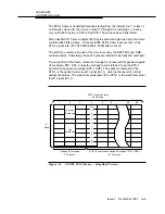
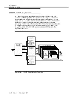
SONET has provisions for multiplexing asynchronous DS1s, synchronous DS1s,
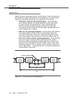
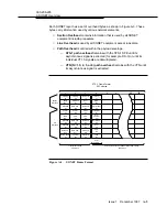
and asynchronous DS3s. Refer to Figure A-5 and Figure A-6.
The first stage in multiplexing is mapping the input DS1 or DS3 tributary. In the
case of DS1 inputs, three time slots (DS0s) are added to the incoming signal thus
becoming a VT1.5. An asynchronous DS1 that fully meets the specified rate is
mapped into the VT1.5 SPE as clear channel input since no framing is needed.
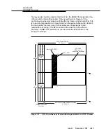
■
Each VT1.5 carries a single DS1 payload.
■
Four VT1.5s are bundled into a VT group (VT-G).
■
Seven VT-Gs are byte-interleaved into an STS-1 frame.
The VT-G to-STS-1 multiplex is a simple byte-interleaving process, so individual
VT signals are easily observable within the STS-1. Thus, cross-connections and
add/drop can be accomplished without the back-to-back multiplexing/multiplexing
steps required by asynchronous signal formats. The structured VTs are now
multiplexed into the STS-1 SPE, and the path, line, and section overhead are
added. The final multiplexing, as shown in Figure A-5, provides the scrambled
STS-
N signal to the optical conversion stage.

