Issue 5 November 2000
363-206-208
Equipment and Front Access Cable Installation for the DDM-2000 OC-12 Multiplexer
Lucent Technologies - Proprietary
See Notice on first page
Equipment Installation
Description
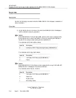
This procedure describes how to install equipment in a bay that is ONLY accessible
from the front. This procedure requires attaching the backplane cables to the shelf prior
to mounting the shelf in the bay.
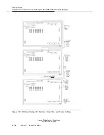
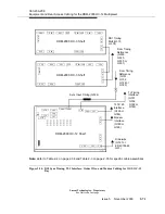
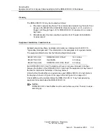
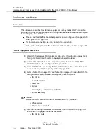
Shelves and heat baffles should be spaced as shown in Figure 3-5 on page 3-50
and Figure 3-6 on page 3-51.
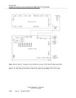
for backplane connections refer to Figure 3-1 on page 3-46.
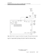
Cables should be placed in the bay frame as shown in Figure 3-2 on page 3-47.
Preshelf Equipment Installation
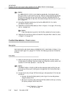
(1) Obtain the front access DS3 cables per Tables 3-1 through 3-4 on pages 3-32
through 3-36 and note the cable to be used with each muldem.
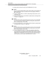
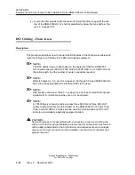
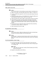
(2) Connect the DS3 cables to their respective connectors on the DDM-2000
OC-12 backplane. Refer to Figure 3-8 on page 3-53.
(3) Dress the DS3 cables, ensuring that the cables will not obstruct the backplane
cover from being installed, per Figure 3-8 on page 3-53.
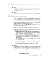
(4) Refer to Table 3-5 on page 3-37 and Table 3-6 on page 3-38 and attach the fol-
lowing front access shelf cables, as required, to the backplane:
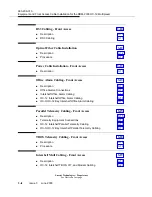
a. DS1 timing
b. TL1/X.25 interface
c. Order wire
d. Modem
e. Telemetry byte-oriented serial (TBOS)
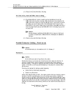
f. Parallel telemetry
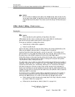
NOTE:
Parallel telemetry and TBOS are not available in OC-12, Release 7.
g. Office alarms
h. Miscellaneous discrete.
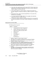
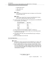
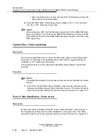
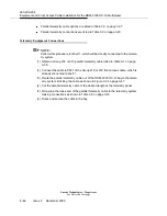
(5) Attach the following front access mult cables, listed in Table 3-5 on page 3-37
and Table 3-6 on page 3-38, to the backplane:
a. DS1 timing mult.
Summary of Contents for DDM-2000 OC-12
Page 4: ......
Page 370: ...GL 22 Issue 5 June 2000 363 206 208 Glossary ...
Page 382: ...363 206 208 Index 1 ...

