Issue 5 November 2000
363-206-208
Equipment and Front Access Cable Installation for the DDM-2000 OC-12 Multiplexer
Lucent Technologies - Proprietary
See Notice on first page
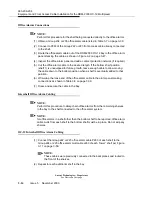
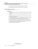
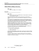
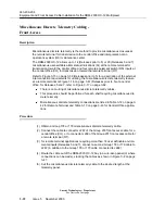
Office Alarms Connections
NOTE:
Perform this procedure for the shelf being connected directly to the office alarms.
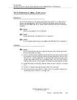
(1) Obtain a Group 234 or 235 office alarm cable listed in Table 3-7 on page 3-39.
(2) Connect to P263 of the Group 222 or 223 front access cable already connected
to the shelf.
(3) Route the office alarm cable out of the DDM-2000 OC-12 bay to the office alarm
panel stacking the cable as shown in Figure 3-2 on page 3-47.
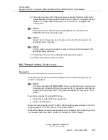
(4) Inspect the office alarm panel and add a contact protection network (if required).
(5) Cut the office alarm cable to the desired length. If the bottom shelf position
(shelf 1) is unequipped for future growth, leave enough cable to allow moving
the cable down to the bottom position when a shelf is eventually added to that
position.
(6) Wire-wrap the loose end of the office alarm cable to the alarm panel making
connections as shown in Table 3-8 on page 3-39.
(7) Dress and secure the cable in the bay.
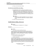
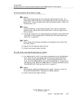
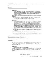
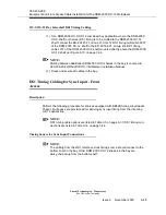
Intershelf Office Alarm Cabling
NOTE:
Perform this procedure to daisy-chain office alarms from the remaining shelves
in the bay to the shelf connected to the office alarm system.
NOTE:
for office alarms in a shelf other than the bottom shelf to be reported, office alarm
cable mults from each shelf to the bottom shelf must be in place. Do not skip any
shelves.
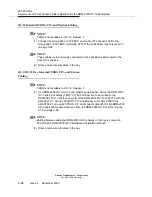
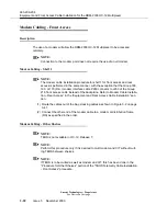
OC-12 Intershelf Office Alarm Cabling
(1) Connect the Group 222 or 223 office alarm cable P263 of each shelf to the
Group 224 or 225 office alarm mult cable J263 of each “lower” shelf per Figure
3-11 on page 3-56.
NOTE:
These cables were previously connected to the backplanes and routed to
the front of the shelves.
(2) Repeat for each additional shelf in the bay.
Summary of Contents for DDM-2000 OC-12
Page 4: ......
Page 370: ...GL 22 Issue 5 June 2000 363 206 208 Glossary ...
Page 382: ...363 206 208 Index 1 ...


