Issue 5 November 2000
363-206-208
Equipment and Front Access Cable Installation for the DDM-2000 OC-12 Multiplexer
Lucent Technologies - Proprietary
See Notice on first page
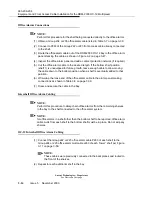
DS1 Timing Cabling for Shelf 1
NOTE:
The DS1 timing procedure for shelf 1 for front access and rear access is per-
formed in the same manner, with the exception that the Group 151, 152, or
153,DS1 timing cable P266 connects to J266 of the Group 210 or 211 front
access cable instead of the backplane. Refer to “DS1 Timing Cable Installation -
Rear Access” in the “Equipment and Rear Access Cable Installation” section.
(1) Route the cable out of the bay, stacking cables as shown in Figure 3-2 on page
3-47.
(2) Cut the DS1 timing cable to the desired length at the DS1 reference clock.
(3) Wire-wrap the loose end of the DS1 timing cable to the DS1 reference clock,
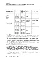
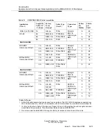
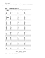
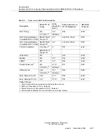
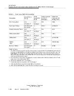
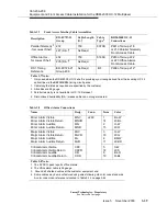
making connections as shown in Table 3-14 on page 3-441.
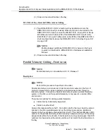
OC-12 Intershelf DS1 Timing Cabling
NOTE:
Perform this procedure when shelf 1 in the same bay will be directly connected to
the DS1 reference clock. The cable added in this procedure is to mult DS1 timing
in a bay to shelf 1. In this procedure shelf 1 will be connected to shelf 2, shelf 2
connected to shelf 3, etc.
NOTE:
for DS1 timing to be delivered to a shelf other than shelf 1, DS1 timing cable
mults from that shelf to shelf 1 must be in place. Do not skip any shelves.
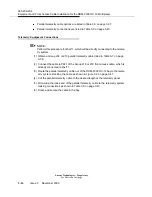
(1) Connect the Group 210 or 211 DS1 timing cable of each shelf J266 to the
Group 212 or 213 DS1 timing mult cable P266 of each “lower” shelf per Figure
3-18 on page 3-63.
NOTE:
These cables were previously connected to the backplanes and routed to the
front of the shelves.
(2) Repeat for each additional shelf in the bay.
(3) Dress and secure all cables in the bay.
Summary of Contents for DDM-2000 OC-12
Page 4: ......
Page 370: ...GL 22 Issue 5 June 2000 363 206 208 Glossary ...
Page 382: ...363 206 208 Index 1 ...

