Issue 5 November 2000
363-206-208
Equipment and Front Access Cable Installation for the DDM-2000 OC-12 Multiplexer
Lucent Technologies - Proprietary
See Notice on first page
Fan Shelf Alarm Connections - Front Access
Description
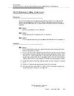
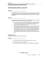
The DDM-2000 OC-12 fan shelf is optionally provided, as required. An alarm indication
is generated by the fan shelf in the event of a functional failure. This alarm can be input
to the DDM-2000 OC-12 shelf as a miscellaneous discrete indication (miscellaneous
discrete #14).
Procedure
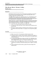
The fan shelf alarm output should connect to the DDM-2000 OC-12 shelf located below
the fan shelf. This connection may be made in one of two ways:
(1) If no other miscellaneous discrete inputs are being connected to the DDM-2000
OC-12 shelf, connect a Group 149 cable between the J1 connector on the fan
shelf alarm cable and J268 of the Group 231 miscellaneous discrete front
access cable of the DDM-2000 OC-12 shelf.
(2) If other miscellaneous discrete inputs in addition to the fan shelf alarm are being
connected to the DDM-2000 OC-12 shelf, connect a Group 181 or Group 147
(D.A.) cable between the J1 connector on the fan shelf alarm cable and the
appropriate wires on the Group 178 or 179 (D.A.) miscellaneous discrete cable
via a miscellaneous terminal strip, in accordance with information provided in
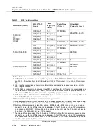
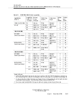
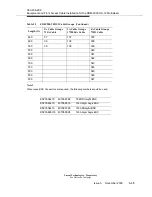
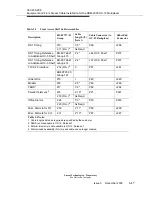
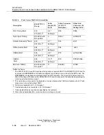
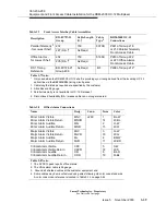
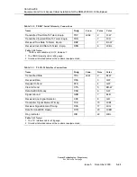
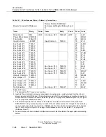
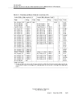
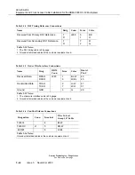
the job specification. Refer to Fan Shelf alarm connections per Table 3-16 on
page 3-44 and the “Miscellaneous Discrete Telemetry Cable Installation” proce-
dure.
Final Operations
Procedure
(1) Verify that all the cables are properly dressed and secured in the bay.
(2) Verify that all cables are properly labeled.
(3) Verify that designation where cables were wire-wrapped are properly labeled.
Summary of Contents for DDM-2000 OC-12
Page 4: ......
Page 370: ...GL 22 Issue 5 June 2000 363 206 208 Glossary ...
Page 382: ...363 206 208 Index 1 ...

