Issue 5 November 2000
363-206-208
Equipment and Front Access Cable Installation for the DDM-2000 OC-12 Multiplexer
Lucent Technologies - Proprietary
See Notice on first page
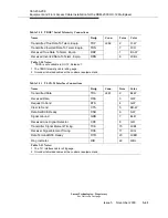
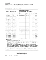
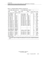
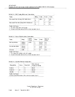
Figure 3-10. Cable Preparation for 219N Connector
* Registered Trademark of Thomas & Betts Corporation.
slug) of the 219P connector. Do not add any additional solder; the
connector has been assembled and crimped.
Soldering of the 219P connector must be done after the 219
Thomas & Betts*
Make sure center conductor is visible in barrel of 219 connector.
Terminal of the 219P connector should slide
Slide outer shield over braid and terminal of 219 connector as
Slide the KS-15712, L20 over the 734A cable as shown in the
(leaving the braided shield only).
Prepare the 734A cable as shown in the following figure:
over cable dielectric but under braided shield
Inner foil shield should be removed from this area
Center conductor to be tinned
WT-414
Crimp KS-15712, L20 outer shield using
solder slug is all that is required.
Apply soldering iron on bottom of barrel (opposite side of solder
crimp tool or equivalent.
Solder slug
Fan braided shield and foil slightly
KS-15712, L20 Outer shield
following figure:
Slide outer shell over 219P connector and secure with screw.
STEP 8:
STEP 2:
STEP 1:
1/8"
7/16"
1/16"
STEP 7:
STEP 6:
STEP 5:
STEP 4:
Cover the 219P connector with KS-21886, L1 tubing.
Outer shield
shown in the following figure:
STEP 3:
Cable dielectric
Summary of Contents for DDM-2000 OC-12
Page 4: ......
Page 370: ...GL 22 Issue 5 June 2000 363 206 208 Glossary ...
Page 382: ...363 206 208 Index 1 ...

