Issue 5 November 2000
363-206-208
DDM-2000 OC-3/OC-12 Bay Installation
Lucent Technologies - Proprietary
See Notice on first page
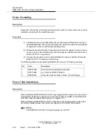
Frame Grounding
Description
All ground connections to the frame shall be made in such a manner as to ensure a low-
resistance contact with the metal framework.
Procedure
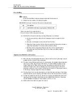
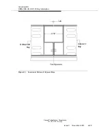
(1) The #6 bare wire ground assembly comes rolled up and attached to the top of
the DDM-2000 bay. The bay ground assembly can be removed and repositioned
or replaced to conform with local grounding codes.
(2) Whenever the ground strap is repositioned, remove the paint as much as neces-
sary to ensure a low-resistance ground and apply an oxidation preventive such
as NO-OX-ID
“A” or equivalent.
(3) Connect the ground wire to the Central Office Ground wire with the Thomas
&
Betts 54720 “C” compression terminal lug
,
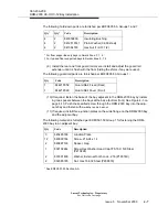
The following material is provided by ED8C501-50, Group 1 for frame grounding:
Power Cable Installation
Description
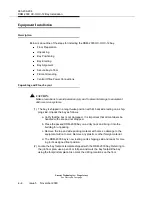
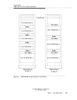
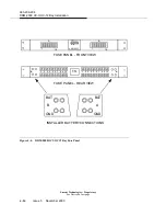
When installing a DDM-2000 OC-3/OC-12 bay equipped with a fuse panel, two pairs of
Central Office feeders are required for connection to BAT and GRD on the DDM-2000
OC3/OC12 bay fuse panel. See Figure 4-4 on page 4-14.
When installing a DDM-2000 OC-3/OC-12 bay that is not equipped with a fuse panel,
the factory installed power riser cables are tapped to the Central Office feeder.
NOTE:
The DDM-2000 OC-3/OC-12 bay is powered by -48 V DC.
Qty
Code
Description
1
846781680
Frame Ground Connection Assembly
1
997775952
Lug, Terminal #54720 T&B Co.
2
840026827
Screw Hex Washer Head .216-24 X.5 Self Tapping
Summary of Contents for DDM-2000 OC-12
Page 4: ......
Page 370: ...GL 22 Issue 5 June 2000 363 206 208 Glossary ...
Page 382: ...363 206 208 Index 1 ...

