Issue 5 November 2000
363-206-208
End-To-End Installation Tests for Ring Applications of the DDM-2000 OC-12 Multiplexer
Lucent Technologies - Proprietary
See Notice on first page
Tools, Test Sets, and Accessories
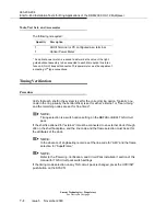
The following is required:
Timing Verification
Procedure
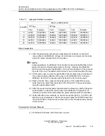
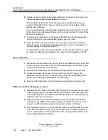
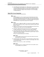
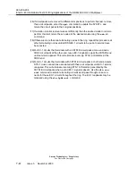
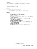
Verify that each shelf in the system is set for the correct timing option. Typically, one
node in the ring (usually the central office) is set for either “external” or “free running”
and the remaining nodes are set for “line timed”.
NOTE:
Timing selection is a switch option setting on the BBF2B or BBF4 TGS circuit
pack.
If the shelf is optioned for “external” it must be connected to an external clock through
J66 on the shelf backplane, and the line code and the frame selection must be set for
the attributes of the clock.
NOTE:
In the absence of engineering records, set the line code for “AMI” and the frame
selection for “SuperFrame.”
NOTE:
Refer to the “Powering, Verification, and Circuit Pack Installation” section of this
manual for TGS circuit pack switch settings.
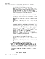
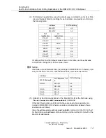
If the timing mode selection on any TGS circuit pack is changed, press the UPD/INIT
push-button on the SYSCTL.
Quantity
Description
1
ASCII Terminal or PC configured as a terminal
1
Optical Power Meter
*
* An optical power meter is required to determine the value of the light-
guide buildout assembly to be connected to each Main optical line inter-
face unit (OLIU) transmit connector. This power meter must be capable of
accepting
ST
®
type connections.
Summary of Contents for DDM-2000 OC-12
Page 4: ......
Page 370: ...GL 22 Issue 5 June 2000 363 206 208 Glossary ...
Page 382: ...363 206 208 Index 1 ...

