Issue 5 November 2000
363-206-208
Equipment and Rear Access Cabling for the DDM-2000 OC-12 Multiplexer
Lucent Technologies - Proprietary
See Notice on first page
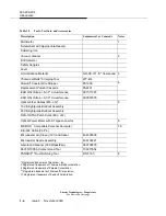
Six conductor cable (1735006A) provides three DS3 In and three DS3 Out
cables to accommodate one full muldem on the DDM-2000 OC-12 shelf. The
734A, 735A, and KS-19224, L2 cables provide one DS3 In cable and one DS3
Out cable to accommodate a partially equipped muldem.
DS3 cables come in a fixed lengths or in a length specified by the customer.
For cable groups with the connector for one end of the cable shipped loose, be
sure to use the proper procedure and crimp tool when assembling this end of the
cable.
!
CAUTION:
Several cable groups come assembled with a connector on each end. Cutting the
cable to a shorter length and installing a new connector on the cable may result in
cable quality substandard to that in the factory and subsequent service outages
may occur. If a new connector must be installed, use the correct connector and
proper crimp tool.
Groups 126 (D.A.) and 136 (D.A.) come with a second cable assembly,
ED-7G001-23, Group 204 cable with a 219P connector on one end, which is
then spliced to the first cable assembly.
Perform the appropriate procedure depending on the cable group being
installed.
NOTE:
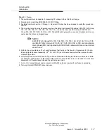
When cabling to a DSX, the DSX becomes an extension of the DDM-2000 back-
plane connections. Thus the IN on the DDM-2000 backplane connects to the IN
of the DSX and the OUT of the DDM-2000 backplane connects to the OUT of the
DSX respectively.
Procedure
NOTE:
Perform the following procedure if this installation involves DS3 cabling.
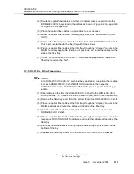
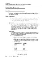
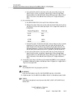
(1) All the DS3 cable assemblies can be used for any muldem. DDM-2000 OC-12
DS3 backplane connectors are J30 through J35 (for muldem A), J36 through
J41 (for muldem B), J42 through J47 (for muldem C), and J48 through J53 (for
muldem D). Connect the cables to the appropriate backplane BNC connectors
as shown in Figure 2-10 on page 2-57.
(2) Route the cables out of the DDM-2000 OC-12 bay per Figure 2-10 on page 2-
57, stacking the cables as shown in Figure 2-2 on page 2-49 or Figure 2-3 on
page 2-50.
Summary of Contents for DDM-2000 OC-12
Page 4: ......
Page 370: ...GL 22 Issue 5 June 2000 363 206 208 Glossary ...
Page 382: ...363 206 208 Index 1 ...

