Issue 5 November 2000
363-206-208
Equipment and Rear Access Cabling for the DDM-2000 OC-12 Multiplexer
Lucent Technologies - Proprietary
See Notice on first page
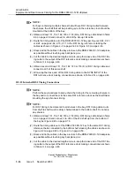
(4) For remote terminal applications requiring more than 14 user definable environ-
mental inputs (Release 5 only), connect a second Group 178, 194 or 179 (D.A.)
cable to P67 (in addition to the Group 178, 194 or 179 (D.A.) cable on P68).
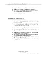
(5) Dress and tie the cables in the bay as close to the DDM-2000 OC-12 backplane
as possible without touching any backplane pins.
(6) Cut the miscellaneous discrete telemetry cable to the desired length at the
telemetry panel.
(7) Wire-wrap the loose end of the miscellaneous discrete telemetry cable to the
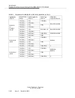
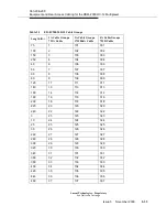
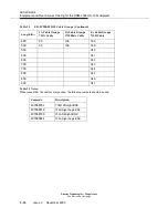
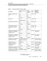
wire-wrap terminal strip, making connections as shown in Table 2-12 on page 2-
44 and Table 2-13 on page 2-45, and Figures 2-18, 2-19 and 2-20 on pages 2-
65, 2-66 and 2-67.
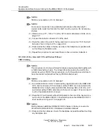
NOTE:
Each miscellaneous discrete telemetry designation is connected to the
DDM-2000 OC-12 by two leads (wires).
NOTE:
For each input, connect one lead to input-common and the other lead to the
appropriate alarm indication.
NOTE:
For each output, connect one lead to output-common and the other lead to the
appropriate alarm indication.
NOTE:
To input the external minor alarm (MN) or power minor alarm (PMNT-IN), con-
nect one lead to the appropriate external alarm source and connect an external
ground to output-common.
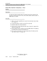
DS1 Timing Cabling - Rear Access
Description
The following procedure is required for cabling to a DS1 timing:external external timing
source for synchronous operation.
NOTE:
For shelves equipped with BBF2B/BBF4 timing circuit packs that are provisioned
for deriving synchronous input timing from the incoming OC-12 optical line, skip
this procedure and continue with “DS1 Timing Cable Installation for Sync Input”.
DS1 timing cable options are listed in Table 2-6 on page 2-39.
Summary of Contents for DDM-2000 OC-12
Page 4: ......
Page 370: ...GL 22 Issue 5 June 2000 363 206 208 Glossary ...
Page 382: ...363 206 208 Index 1 ...

