Issue 5 November 2000
363-206-208
Equipment and Rear Access Cabling for the DDM-2000 OC-12 Multiplexer
Lucent Technologies - Proprietary
See Notice on first page
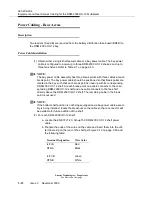
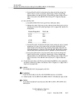
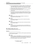
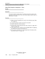
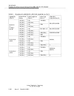
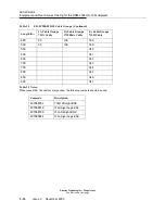
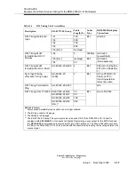
DS1 timing connections are listed in Table 2-14 on page 2-46.
Connections to Timing Source
NOTE:
The cabling from the DS1 reference clock timing source should connect to the
bottom shelf in the bay. Other DDM-2000 OC-12 shelves in the bay are daisy-
chained up from the bottom shelf.
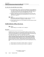
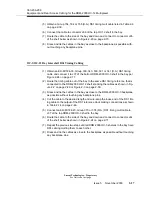
(1) Obtain a Group 151, 152, 182, 183 or 153 (D.A.) DS1 timing cable listed in Table
2-6 on page 2-39.
(2) Connect the cable to connector J66 of shelf 1.
(3) Route the timing cable out of the DDM-2000 OC-12 bay per Figure 2-17 on
page 2-64 to the DS1 timing reference, stacking the cables as shown in Figure
2-2 on page 2-49 or Figure 2-3 on page 2-50.
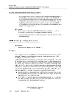
(4) Dress and tie the cables in the bay as close to the DDM-2000 OC-12 backplane
as possible without touching any backplane pins.
(5) Cut the cable to the desired length. If the bottom shelf (shelf 1) position is
unequipped for future growth, leave enough cable to allow moving the cable
down to the bottom position when the shelf is eventually added.
(6) Wire-wrap the loose end of the DS1 timing cable to the DS1 reference clock
making connections as shown in Table 2-14 on page 2-46.
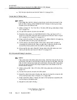
OC-12 Intershelf Timing Connections
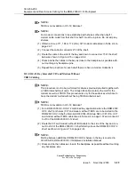
NOTE:
These procedures should be performed to daisy-chain the timing for the remain-
ing shelves in the bay to the shelf that is directly connected to the DS1 reference
clock. For DS1 timing to be delivered to all shelves in the bay, DS1 timing cable
mults from shelf to shelf must be daisy-chained down to the bottom shelf. No
shelf should be skipped.
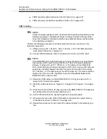
(1) Obtain a Group 154, 184 or 155 (D.A.) DS1 timing cable listed in Table 2-6 on
page 2-39.
(1) Connect the cable to connector J66 of the shelf.
(1) Route the cable to the side of the bay and down and connect to connector J65
of the shelf below as shown in Figure 2-17 on page 2-64.
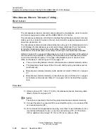
(1) Dress and tie the cables in the bay as close to the backplane as possible with-
out touching any backplane pins.
(1) Repeat for each shelf in the bay.
Summary of Contents for DDM-2000 OC-12
Page 4: ......
Page 370: ...GL 22 Issue 5 June 2000 363 206 208 Glossary ...
Page 382: ...363 206 208 Index 1 ...

