363-206-295
Shelf Descriptions and Configurations
3-12
Issue 1
December 1997
OC-12 Ring Configuration (DS1/EC-1 Low-Speed
Interfaces)
3
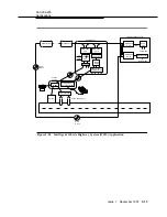
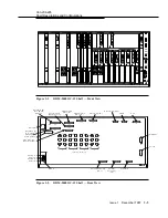
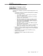
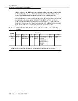
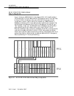
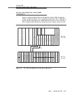
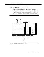
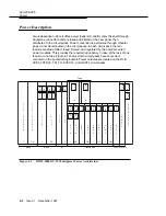
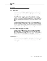
Figure 3-7 shows an OC-12 configuration using DS1/EC-1 low-speed interfaces.
Interface to the low-speed shelf is made through the IS-3 (or OC-3) circuit packs,
one service and one protection pack per interface. The IS-3 circuit packs replace
the OLIU circuit packs in the main slots on the DDM-2000 OC-3 shelf. This
configuration supports a high-speed OC-12 interface with 84 DS1 terminations
per DDM-2000 OC-3 shelf, up to a maximum of 336 DS1 terminations.
Figure 3-7.
OC-12 Ring Configuration (DS1/EC-1 Low-Speed Interfaces)
M
M
M
M
O
O
O
O
A
B
G
1
2
G
1
7
7
A
B
1
7
7
T
T
T
S
I
T
S
I
1
1
2(P)
2(P)
1
L
I
U
L
I
U
L
I
U
L
I
U
P
P
B
L
K
1
2
U
2(P)
2(P)
P
P
B
L
K
O
L
I
1
2(P)
1
E
S
Y
S
C
T
L
O
H
C
T
L
U
S
E
R
DDM-2000
P
A
N
E
L
OC-12 Shelf
1
U
O
L
I
D
D
D
D
D
D
D
D
D
S
1
S
1
S
1
S
1
S
1
S
1
S
1
S
1
S
1
D
S
1
D
S
1
D
S
1
O
S
Y
U
S
E
T
M
M
G
X
R
X
R
X
R
X
R
V
V
V
V
X
R
X
R
V
V
2
T
G
O
L
I
U
O
L
I
U
O
O
O
O
O
O
1
1
1
1
1
2(P)
2(P)
2(P)
2(P)
1
P
B
L
K
P
B
L
K
2(P)
1
7
7
C
A
P
1
7
7
C
A
P
5
6
7
8(P)
5
6
7
8(P)
D
S
D
S
D
S
D
S
D
S
D
S
D
S
D
S
5
6
7
D
S
D
S
D
S
DDM-2000
H
C
S
T
C
8(P)
D
S
L
T
L
OC-3 Shelf
R
P
A
N
1
2
3
1
1
1
1
2
3
4
4
1
1
1
1
1
1
2
3
1
1
1
4
1
E
L
5
6
7
M
X
R
M
X
R
M
X
R
M
X
R
M
X
R
X
R
T
G
2
D
S
1
D
S
1
D
S
1
M
8(P)
5
6
7
D
S
1
D
S
1
D
S
1
D
S
1
D
S
1
8(P)
V
V
V
V
V
V
T
G
D
S
D
S
D
S
5
6
7
D
S
1
D
S
1
D
S
1
D
S
D
S
D
S
D
S
D
S
D
S
D
S
D
S
1
2
3
1
1
1
1
1
1
1
1
2(P)
2(P)
2(P)
2(P)
1
2
3
1
2
3
4
4
1
1
1
1
1
1
1
1
O
O
O
O
O
O
O
L
I
U
O
L
I
U
DDM-2000
D
S
1
D
S
O
H
C
T
L
S
Y
S
C
T
L
U
S
E
R
P
A
N
E
8(P)
OC-3 Shelf
4
1
L
3
S
T
S
1
E
3
S
T
S
OC-3/IS-3
OC-3/
IS-3

