363-206-295
Circuit Pack Descriptions
Issue 1
December 1997
7-29
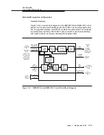
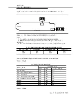
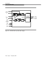
On the BBG11 3DS3 side, the DS3 inputs from a DSX-3 are sent to both the
active and standby BBG11 3DS3 circuit packs. Only the active unit selects the
DS3 input. The SYSCTL circuit pack supervises the state of the active and
standby units so that the relay state of each is always the inverse of the other. The
hybrid on the active unit splits the DS3 input signals and sends them to the
standby unit and to its own receiver. To implement a protection switch on the DS3
side, the SYSCTL switches the relays on each unit to their opposite state.
When a BBG11 3DS3 is removed, shorting contacts on the backplane connector
operate so that the DS3 input signal from its companion unit is returned for proper
termination.
Fault Detection Circuitry
7
Monitoring and Testing.
7
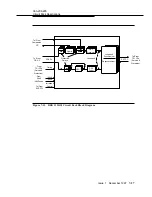
The BBG11 3DS3 circuit pack has in-service and
out-of-service built-in test capability. In-service testing is continuous and errors
are reported when they occur to the SYSCTL via the intra-shelf control bus. An
out-of-service test is performed whenever the BBG11 3DS3 circuit pack is
inserted or recovers from a transient failure.
Loopbacks.
7
Two loopbacks are provided for each DS3 interface on the BBG11
3DS3 circuit pack. The terminal loopback bridges the DS3 desynchronizer output
signal (transmitted towards the DSX-3) back into the DS3 synchronizer input.
Operation of this loopback does not affect the signal transmitted to the DSX-3.
The facility loopback bridges the STS-1 output signal to the TSI back towards the
DSX-3. Operation of this loopback does not affect the signal transmitted to the
fiber. Both loopbacks are controlled by the SYSCTL through the intra-shelf control
bus.
Power Circuitry
7
The BBG11 3DS3 circuit pack receives two sources of
−
48 volts that are in turn
diode ORed, fused, and filtered before conversion to +5 volts to power the rest of
the circuit pack. A failure of the fuse or converter causes the red FAULT LED to
light.

