363-206-295
Circuit Pack Descriptions
Issue 1
December 1997
7-47
General Description of Operation
7
The BCP3 provides the 51.84 MHz clock and the 8-kHz frame pulse to all main-b
and function units service and protection circuit packs. In the receive direction, the
BCP3 receives twelve 51.84 Mb/s STS-1s from an active main-b circuit pack and
groups them into sets of three STS-1s. Each set of three STS-1s is connected to
both active and standby function unit circuit packs. In the transmit direction, the
BCP3 accepts twelve STS-1s from active function unit circuit packs and transfers
them to the main-b-1 and main-b-2 circuit packs. The BCP3 also interfaces to the
SYSCTL and receives timing signals from the TGS circuit packs.
Cross-connections can be made from main-to-main or main to any function unit.
Detailed Description of Operation
7
Transmission Circuitry
7
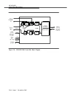
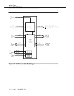
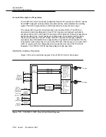
Figure 7-20 provides an overall block diagram of the BCP3 circuit pack.
Transmit Direction.
7
In the transmit direction, under control of the SYSCTL circuit
pack, the BCP3 selects 12 STS-1 signals from the function unit slots and sends
them to the main-b slots.
Receive Direction.
7
Under control of the SYSCTL circuit pack, the BCP3 selects
12 STS-1 signals from the main-b slots. The 12 STS-1 signals are transmitted to
the function unit slots.
Clock and Frame SYNC Distribution
7
Each BCP3 circuit pack receives a 51.84-MHz clock and an associated 8-kHz
frame pulse from each of the active and standby TGS circuit packs. Each BCP3
provides balanced clocks at 51.84 MHz and balanced frame sync at 8 kHz to the
main-b-1 and main-b-2 circuit packs, and the four active and four standby function
unit circuit packs. It also provides a pair of clock and frame sync to the other BCP3
circuit pack. The BCP3, under control of the SYSCTL circuit pack, normally
selects signals from the active TGS. If a failure of the clock or frame is detected,
the BCP3 can automatically switch to the standby TGS circuit pack. The SYSCTL
can inhibit autonomous clock selection.

