363-206-295
Circuit Pack Descriptions
Issue 1
December 1997
7-49
Maintenance Features and Modes
7
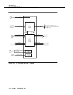
The BCP3 circuit pack communicates with the SYSCTL circuit pack via a control
interface.
Transmit Direction.
7
The BCP3 receives 12 sets of STS-1 data signals, one each
from the active and standby function unit circuit packs. One set is selected by
SYSCTL request.
Receive Direction.
7
The BCP3 receives two sets of 12 STS-1 data signals, one
each from the active and standby main-b circuit packs. One set is selected by
SYSCTL provisioning.
Performance Monitoring.
7
The BCP3 circuit pack monitors the STS path bit
interleaved parity (BIP-8) on all selected inputs from the main-b and function unit
circuit packs.
Other Functions:
7
■
Circuit pack insertion and removal detection
■
FAULT LED (red) control (via control interface)
■
ACTIVE LED (green) control (via control interface)
■
+5 volt power module failure
■
Circuit pack version and type recognition (EEPROM via control interface).
Power Circuitry
7
The BCP3 receives
−
48 volts which are diode ORed, fused, and filtered prior to
conversion to the +5 volt source for the circuit pack. A failure of the fuse or
converter causes the red FAULT LED to light.


