363-206-295
Circuit Pack Descriptions
7-52
Issue 1
December 1997
General Description of Operation
7
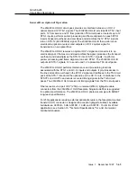
The 21D/21D-U OLIU circuit pack multiplexes three STS-1 signals to an STS-3, inserts
the SONET transport overhead bytes (line and section), and scrambles the resulting
signal. This STS-3 signal drives an LED transmitter to create the IS-3 output.
The received IS-3 signal is converted back to an electrical STS-3. This STS-3 is
descrambled and demultiplexed to three STS-1 signals, and transport overhead is
accessed. Some of the overhead (for example, section datacom channel) is passed via
serial data links to the control packs, while other bytes (for example framing, parity
check) are processed on-board. Finally, the STS-1 signals run through a pointer-
processing step (interpretation and regeneration) to guarantee frame alignment to the
local system clock before they are sent to the TSI slots. Fiber access is via a pair of
ST
(21D) or universal (21D-U) lightguide cable connectors from the 21D/21D-U OLIU
faceplate. The 21D/21D-U OLIU operates
only on multimode cable.
Detailed Description of Operation
7
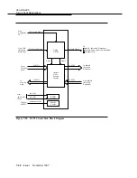
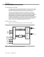
Figure 7-22 is an overall block diagram of the 21D/21D-U OLIU circuit pack.
Figure 7-22. 21D/21D-U OLIU Circuit Pack Block Diagram
Byte Interleaves
IS-3
Converts IS-3
IS-3
into IS-3
SONET
From
(Service &
OHCTL CP
TSI CPs
STS-1 #3
STS-1 #2
STS-1 #1
Overhead
Timing
-48V B
-48V A
Control
Intrashelf
SYSCTL
To/From
-48V Fuses
Shelf
From
To/From
Protection)
Rx Fiber
Tx Fiber
Disinterleaves a
Processes
3 STS-1s
STS-3 into
Byte
OH
Section and Line
to STS-3
Demultiplexer
Converts STS-3
Bytes of STS-1 #1
and Line OH
Write Section
a STS-3
3 STS-1s into
Multiplexer
STS-1 #3
STS-1 #2
STS-1 #1
STS-1 #3
STS-1 #2
STS-1 #1
Processors
Pointer
TSI CPs
STS-1
STS-1
Protection)
(Service &
To/From
STS-1
Routing
STS-1


