background image

Lucent Lineage

®

 2000 ECS Battery Plant H569-408

4 - 8  Maintenance  

Issue 2 July 1996

1. Remove rectifier in position directly beneath LVD/R 

contactor (position 1), if present.

2. Open distribution panel and unplug connector P501 from 

J501 on LVD/Fuse board (CP5). Leave cable dressed.

3. Disconnect and label the five quick connects from the 

contactor coil and auxiliary switch.

4. Unbolt and remove contactor. 

5. Reconnect quick connect leads to new contactor and then 

mount new contactor using hardware from Step 4.

6. Plug P501 into J501 on LVD/Fuse board (CP5) and verify 

that contactor closes.

7. Replace rectifier and turn on.

8. Close distribution panel and verify that “LVD FAIL” and 

“LVD OPEN” lights are not lit.

LVD/Fuse Board

(CP5)

Replacement

The following equipment is required:

standard screwdriver

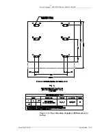
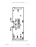
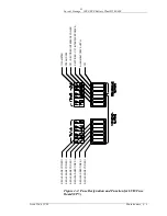
Procedure: (Refer to Figure 3-3 and T-82670-30 drawing)

1. Open distribution panel.

2. Unplug the following connectors from the LVD/Fuse 

Board (CP5). Leave the cables dressed.

P502 from J502
P506 from J506
P501 from J501
P504 from J504
Quick connect from E501

3. Remove the cover over the LVD/Fuse Board and then 

remove the insulated standoffs to free the board.

4. Set jumpers J505.1 and J505.2 on replacement LVD/Fuse 

Board (CP5) per H569-408 drawing for desired disconnect 
voltage.

Warning

Procedures in this paragraph may cause power alarms to be 
issued temporarily. Notify the alarm reporting center before 
starting any replacement procedure on an operating plant.

Summary of Contents for H569-408

Page 1: ...INEAGE 2000 300 Ampere 48 Volt Evolutionary Control System Battery Plant Notice Every effort was made to ensure that the information in this document was complete and accurate at the time of printing However information is subject to change 1996 Lucent Technologies All Rights Reserved Printed in U S A ...

Page 2: ...ca 1 6 Europe Middle East and Africa 1 6 Asia Pacific Region 1 6 Customer Service 1 6 2 Product Description Plant Specifications 2 1 Typical Battery Plant Description 2 4 Battery Plant Subsystems 2 4 ECS Battery Plant Physical Description 2 6 Introduction 2 6 Initial Bay 2 6 Supplementary Bays 2 7 ECS Battery Plant Subsystems 2 7 Rectifier 2 7 Batteries 2 8 Controller 2 9 DC Distribution 2 9 ECS D...

Page 3: ... Plant Growth 3 13 Adding a Load Circuit 3 13 4 Maintenance Controls and Indicators 4 1 Controller and Rectifier 4 1 CP5 Fuse Board LEDs and Fuses 4 1 DC Circuit Breakers 4 2 Troubleshooting 4 2 Open Distribution Breaker 4 5 Red LVD OPEN LED Lit 4 5 Yellow LVD FAIL LED Lit 4 5 Blown Fuse on CP5 4 6 Repair and Replacement 4 6 Load Circuit Breaker Replacement 4 6 LVD R Contactor Replacement 4 7 LVD ...

Page 4: ...s 1 4 Figure 2 1 Block Diagram of Typical Battery Plant 2 5 Figure 2 2 ECS Battery Plant Block Diagram 2 7 Figure 2 3 ECS Distribution Bus Bars 2 10 Figure 2 4 Plug In Circuit Breaker Mounting 2 11 Figure 3 1 Typical Floor Mounting Detail 3 8 Figure 3 2 Floor Mounting Template All Dimensions in Inches 3 9 Figure 3 3 LVD Fuse Board CP5 Jumper Locations 3 10 Figure 4 1 Fuse Designation and Function ...

Page 5: ...del H569 408 2 1 Table 2 B Ordering Guide for H569 408 ECS 300 Ampere 48 Volt Battery Plant 2 15 Table 3 A Minimum Torque For All Electrical Connections 3 4 Table 3 B Torque and Minimum Yield Strength for Mechanical Connections Using Hex Head Cap Screws 3 5 Table 3C Installation Reference Documents 3 6 Table 4 A Troubleshooting 4 4 Warranty Period 5 2 ...

Page 6: ...in Figure 1 1 This member of the ECS family of battery plants operates from a nominal 208 240 volt ac 50 60 Hz source It offers a 300 ampere total plant capacity with a nominal 48 volt dc output in a totally integrated energy system The basic plant consists of charge and discharge bus bars with optional low voltage disconnect a distribution panel capable of accepting up to 42 circuit breakers an E...

Page 7: ...90 042 is part of a set of product manuals which provide information on the LINEAGE 2000 Evolutionary Control System ECS Battery Plant and its components This manual should be inserted after the PLANT tab in the LINEAGE 2000 Battery Plant Binder The binder contains tabs for the other manuals in the set such as Controller Rectifier and Battery manuals Each manual contains a technical description of...

Page 8: ...nt H569 408 Issue 2 July 1996 Introduction 1 3 Figure 1 1 LINEAGE 2000 ECS Battery Plant Model H569 408 Initial Bay Lucent ONE STRING VR SERIES BATTERIES ECS CONTROLLER SR50 48V RECTIFIER CIRCUIT BREAKER AND FUSE BOARD DISTRUBUTION PANEL ...

Page 9: ...Lucent Lineage 2000 ECS Battery Plant H569 408 1 4 Introduction Issue 2 July 1996 Figure 1 2 VR Battery Supplementary Bay Configurations ...

Page 10: ...ou hold an extended warranty or contractual agreement Central and South America If you need product technical support contact your local Field Support Regional Technical Assistance Center or contact your sales representative who will be happy to discuss your specific needs Europe Middle East and Africa If you need product technical support contact your local Field Support Regional Technical Assist...

Page 11: ...uss your individual situation Asia Pacific Region If you need to return a product for repair your sales representative will be happy to discuss your individual situation Customer Service For customer service any other product or service information or for additional copies of this manual or other Lucent Technologies documents call 1 800 THE 1PWR 1 800 843 1797 Specify the select code number for ma...

Page 12: ...Vdc 48 Vdc nominal Float Voltage 47 58 5 Vdc 48 Vdc nominal Plant Current Rating 300 amperes Plant Shunt 300 amperes maximum at 50 millivolts LVD R Voltage Settings 40 5 or 42 5 Vdc Controller Basic 113A Microprocessor option circuit pack BAB1 Datalogger option circuit pack BAC1 BAC2 Rectifier Shelf Assembly 2 maximum each mounts 3 rectifiers Rectifiers Type LINEAGE 2000 SR50 48V Rating 48 Vdc nom...

Page 13: ...567 mm Dimensions Height 84 inches 2134 mm Width 26 inches 660 mm Depth 26 inches 660 mm G 1 or G 2 plant and G 41 or G 42 battery stand Weight approximate Initial Bay G 1 or G 2 3 Deep Battery Module Stand with six rectifiers 495 lbs 225 kg with six rectifiers and VR Series batteries 2370 pounds 1075 kilograms Supplementary Battery Bay with one string VR 375 Ah batteries 2085 lbs 946 kg Rectifier...

Page 14: ...ative humidity Radiated Conducted Emissions FCC Level A Electromagnetic immunity 10V m over the range of 20 to 2000 MHz Notes 1 Specified at 55 5 Vdc 300 amperes output and nominal input voltages and frequencies 2 Measured at 6 feet 2 meters from the rectifiers installed in plant Table 2 A LINEAGE 2000 Battery Plant Specifications Model H569 408 ...

Page 15: ...r for a specific period of time In normal practice battery capacity is sized to provide 3 to 8 hours of reserve time Battery Plant Subsystems AC Distribution connects the commercial and or standby ac power sources to the rectifiers within the plant and provides overcurrent protection This subsystem is usually supplied by the customer Rectifiers convert an ac source voltage into the dc voltage leve...

Page 16: ...Lucent Lineage 2000 ECS Battery Plant H569 408 Issue 2 July 1996 Product Description 2 5 Figure 2 1 Block Diagram of Typical Battery Plant ...

Page 17: ... and to minimize maintenance These advantages are realized by the application of Switch Mode Rectifier SR and Valve Regulated VR battery technologies and a unique plug in rectifier and circuit breaker design The ECS battery plant is designed as a totally integrated energy system package It is a compact and complete system containing a controller rectifiers circuit breaker distribution panel and op...

Page 18: ...e ECS battery plant providing a total battery capacity of 2625 ampere hours at a 10 hour rate ECS Battery Plant Subsystems Figure 2 2 illustrates the arrangement and interconnections of the ECS Battery Plant subsystems from the ac input to the dc output These subsystems are described below Rectifier The LINEAGE 2000 SR Series rectifiers are designed specifically for applications where small size l...

Page 19: ...mum of three individual 50 ampere rectifiers The ECS plant is equipped with two rectifier shelf assemblies for a total capacity of six SR Series 50 ampere rectifiers See the LINEAGE 2000 SR Series rectifier product manual for additional information Batteries The LINEAGE 2000 VR Series battery is designed specifically for use in the ECS battery plant Selection of the VR Series battery enables one t...

Page 20: ...p 5 with the addition of a voice response feature The datalogger board may be used in conjunction with the microcomputer option to provide general purpose ac and dc voltage and current monitoring and control This board is available as Group 8 or 9 on H569 408 Group 9 is the same as Group 8 with the addition of a remote termination panel allowing external connection to the board from outside the co...

Page 21: ...ge 2000 ECS Battery Plant H569 408 2 10 Product Description Issue 2 July 1996 Figure 2 3 ECS Distribution Bus Bars R1 LVD R K1 OR STRAP BATTERY BUS 2 CHARGE RETURN BATTERY BUS 1 TO LOAD DISCHARGE RETURN BUS TO LOAD ...

Page 22: ...Lucent Lineage 2000 ECS Battery Plant H569 408 Issue 2 July 1996 Product Description 2 11 Figure 2 4 Plug In Circuit Breaker Mounting ...

Page 23: ...ed to measure the total current supplied to the load from the rectifiers and or batteries The shunt has a full scale rating of 50 millivolts at the maximum plant current of 300 amperes The shunt millivolt signal is sent via the CP5 Fuse Board to the controller where it is translated back to amperes and displayed on the digital meter Low Voltage Battery Disconnect Reconnect LVD R Feature In unatten...

Page 24: ...IL LED but the contactor will stay closed A Fuse Alarm Minor MNF is issued when a LVD circuit fails lighting a yellow LED on the controller front panel and sending Power Minor PMN alarms to the alarm reporting center Circuit Breakers The standard dc distribution panel see Figure 2 5 can accommodate a maximum of 42 circuit breakers The circuit breakers are plug in style KS 23616 and are available i...

Page 25: ...ight shelf stand including two additional strings of 2VR375E VR batteries and battery cables would look like the following Note G items from H569 408 should be ordered as separate line items Do not format as equipped with e w items Item Qty Description 1 1 H569 408 G 1 48V 300 AMP ECS Plant 2 5 H569 408 G 4 SR50 48V Rectifier 3 5 H569 408 G 5 Microprocessor Board 4 15 H569 408 G 12 20 Amp Breaker ...

Page 26: ...h voice response feature 8 Provides an optional datalogger circuit pack for data acquisition Group 8 always requires a Group 5 or 7 circuit pack 9 Same as Group 8 with remote termination panel The remote termination panel allows connection to the datalogger circuit pack external to the controller 11 Provides one 10 ampere circuit breaker 12 Provides one 20 ampere circuit breaker 13 Provides one 30...

Page 27: ... provide one battery string disconnect one per battery string D Optional equipment to provide one remote power off switch to be used in conjunction with Group C one required per plant K2 Equipment and hardware in addition to Group 1 and 2 for rear cover in upper half of bay K10 Optional equipment for plant controller equipped with Group 5 CP2 Provides an upgrade kit to add the voice response featu...

Page 28: ... LINEAGE 2000 SR series rectifier and Rectifier Shelf Assembly RSA and the LINEAGE 2000 VR series battery may be found in the following documents ECS Contoller Assembly and Ordering drawing J85501D 1 Wiring Diagram None Schematic Diagram SD 82669 01 Product Manual 167 790 031 Optional Circuit Pack Product Manual 167 790 108 SR Series Rectifiers and Rectifier Shelf Assembly Assembly and Ordering dr...

Page 29: ...ed to check the integrity of the installation effort Upgrades retrofits and replacement of equipment in the controller rectifier and battery subsystems are covered in their respective manuals The framework rectifier controller and dc distribution subsystems described in Section 2 are factory tested as a system The controller and distribution subsystems are shipped assembled to the framework ready ...

Page 30: ...s dc Power supply variable from zero to 60 volts dc at 2 amperes Supply should have both coarse and fine output controls Six clip leads each capable of carrying 3 amperes Suggested Installation Sequence General Information 1 The plant may be wired with ac from the left side or the right side Typical routing of ac dc and control cabling is shown on the plant assembly drawing H569 408 Connection poi...

Page 31: ...e necessary to complete the following sequence of tasks Step A Unpacking Handling Frame Installation 1 Before opening the packaging carefully inspect the outside in the presence of shipping personnel for signs of damage If damaged follow the shipping carrier s procedure for filing a damage claim 2 To ensure personnel safety and equipment protection use appropriate equipment during handling of crat...

Page 32: ...ch thick tapped copper bars use No 8 No 10 or 1 4 inch machine screws to minimize applicable torque When larger size screws are required provide captive type steel nuts or reduce torques 8 Torque recommendations are also suitable for all non ferrous fasteners except aluminum 9 Where application permits hex cap screws should be used Table 3 A Minimum Torque For All Electrical Connections Screw Size...

Page 33: ...Mechanical Connections Using Hex Head Cap Screws Cap Screw Diameter Grade 2 Minimum Yield Strength PSI Torque Ft Lb UNRC 1 4 3 16 3 8 7 16 1 2 9 16 5 8 3 4 7 8 1 1 1 8 1 1 4 1 38 1 1 2 57 000 57 000 57 000 57 000 57 000 57 000 57 000 57 000 36 000 36 000 36 000 36 000 36 000 36 000 5 12 22 35 54 77 107 190 193 290 410 580 760 1010 ...

Page 34: ...ce alarm wiring f Run other controller wiring g Set up other optional circuit packs Table 3C Installation Reference Documents Step Procedure Reference Document A Unpacking This manual Sequence of Tasks Step A B Battery Stand Assembly Battery Manual 157 622 010 J85504C 1 C Cable Support and Ground System Job Application Drawings D Controller Setup and LVD Test Controller Manual E AC Wiring Rectifie...

Page 35: ...ins 2 and 3 of their respective connectors 3 Refer to the ECS controller manual for acceptance testing procedures for the LVD Fuse circuit pack and the associated LVD R option Step E AC Wiring Rectifier Installation and Test Refer to the installation and start up procedure in the Rectifier manual for the following steps Wire AC Set up Plug in Test Before proceeding verify that all rectifier output...

Page 36: ...Lucent Lineage 2000 ECS Battery Plant H569 408 3 8 Installation Issue 2 July 1996 Figure 3 1 Typical Floor Mounting Detail 846844520 FLOOR ANCHOR BOLT KIT HSLB M16 25 HILTI ...

Page 37: ...Lucent Lineage 2000 ECS Battery Plant H569 408 Issue 2 July 1996 Installation 3 9 Figure 3 2 Floor Mounting Template All Dimensions in Inches ...

Page 38: ...Lucent Lineage 2000 ECS Battery Plant H569 408 3 10 Installation Issue 2 July 1996 Figure 3 3 LVD Fuse Board CP5 Jumper Locations ...

Page 39: ... fuses in CP5 Fuse Board Match the fuse ratings and positions as indicated on the distribution cover panel Step G Load Wiring Open the dc distribution cover panel by turning the two 1 4 turn fasteners located on the front of the panel DANGER The next steps in this procedure will apply battery power to the battery plant Before contacting any uninsulated conductor surfaces always use a voltmeter to ...

Page 40: ... not be provided with the dc distribution panel as ordered Spare circuit breakers maybe stored in distribution panel if in the OFF position Leads may be run to spare circuit breaker positions in anticipation of future growth similarly to prewiring rectifier ac input in Step E above Recommendations for routing and dressing of load leads as they leave the battery plant and enter the cable rack syste...

Page 41: ...s evolve equipment may be readily added to the battery plant to provide any of the following Expanded controller features Additional rectifier capacity Increased battery capacity Additional load circuits Procedures for adding controller features rectifiers and batteries to an operating plant are described in the installation sections of the associated subsystem manuals The procedure to add load ci...

Page 42: ... available position verify that the breaker is OFF If a new breaker must be added switch it to the OFF position Plug in the new breaker If possible visually verify that line load and alarm connectors are properly mated See Figure 2 4 Step E If leads have not already been run to the intended load from a spare circuit breaker position e g during the initial plant installation install these leads by ...

Page 43: ...reaker If the circuit breaker trips immediately when turned on this may be due to inrush current and does not necessarily indicate a fault condition Attempt to close the circuit breaker a second time If the breaker trips again check the wiring to the load circuit Warning Before applying power to any individual load follow the power up instructions as provided in the associated load equipment docum...

Page 44: ... OPEN LED indicates that the disconnect reconnect contactor is open and therefore that batteries are disconnected from the rest of the battery plant The yellow LVD FAIL LED indicates that only one of the two redundant low voltage detectors has directed the contactor to open and that the disconnect circuit may have failed Fuses F1 through F12 are also located on the CP5 LVD Fuse Board and provide p...

Page 45: ...eaker which is supplying a load may be turned off manually but this may affect service to the load If a breaker has tripped off the overcurrent problem should be cleared before restoring power to the load by resetting the breaker See paragraph Troubleshooting for information on tripped breakers Troubleshooting Table 4 A provides a list of observable trouble conditions their possible causes and the...

Page 46: ...4 1 Fuse Designation and Function for LVD Fuse Board CP5 113A METER CP2 AND CP3 CP1 RECTIFIER INTERFACE POWER RECTIFIER CP1 INTERFACE POWER ALARM BATTERY SUPPLY CP1 REG LEAD RECTIFIER 1 REG LEAD RECTIFIER 1 REG LEAD RECTIFIER 1 REG LEAD RECTIFIER 1 REG LEAD RECTIFIER 1 REG LEAD RECTIFIER 1 ...

Page 47: ...eshooting in Controller Manual Rectifier Red or yellow LEDs lit No LEDs or Display lit No output low output Oscillation Open output breaker See Troubleshooting in Rectifier Manual DC Distribution Subsystem Open distribution breaker a manually turned off b overcurrent trip c breaker failure Open Distribution Breaker LVD OPEN LED lit a failed LVD contactor b low voltage c faulty wiring d LVD circuit...

Page 48: ...ow Red LVD OPEN LED Lit A lit red LVD OPEN LED indicates that the LVD Contactor is de energized i e open The contactor may be open due to one of the following reasons Plant voltage is below the disconnect threshold The contactor has failed and must be replaced See procedure LVD R Contactor Replacement below There is an open circuit in the wiring that powers the contactor Check the cable assembly f...

Page 49: ... breaker bus bar should be approximately the float voltage of the plant If the faulty breaker is in fact still closed the load equipment which it powers must be shut down so that no current flows through the breaker STEP E Unplug the faulty breaker from the printed wiring board STEP F Switch the new circuit breaker to the OFF position before plugging it in STEP G Plug in the new breaker ensuring t...

Page 50: ... are made Contactor coil has failed THE CONTACTOR IS OPEN The rectifiers are carrying the load off battery with excess capacity available for charging the batteries Battery string s are at a voltage below the rectifier voltage in a state of partial or complete discharge LVD OPEN LED is lit on the distribution front panel The following equipment is required socket wrench with insulated handle 1 2 i...

Page 51: ... distribution panel and verify that LVD FAIL and LVD OPEN lights are not lit LVD Fuse Board CP5 Replacement The following equipment is required standard screwdriver Procedure Refer to Figure 3 3 and T 82670 30 drawing 1 Open distribution panel 2 Unplug the following connectors from the LVD Fuse Board CP5 Leave the cables dressed P502 from J502 P506 from J506 P501 from J501 P504 from J504 Quick con...

Page 52: ...t may be ordered as spare parts For exact ordering codes refer to recommended spares information on the H569 408 drawing Rectifiers and fans LVD Fuse Board CP5 Fuses F1 to F12 Load Circuit Breakers CB1 to CB42 Controller Circuit Packs e g 113A CU Refer to the Controller manual for details on spare controller circuit packs In addition to these items any piece part may be ordered that is identified ...

Page 53: ...er to the extent permitted does hereby assign to Customer the warranties given to Seller by its Vendor of such Vendor Items such assignment to be effective upon Customer s acceptance of such Vendor Items With respect to Vendor items recommended by Seller in its specifications for which the Vendor s warranty cannot be assigned to Customer or if assigned less than Sixty 60 days remain of the Vendor ...

Page 54: ... the Product is not readily returnable for repair Seller will repair the Product at Customer s site With respect to Cable and Wire Products manufactured by Seller which Seller elects to repair but which are not readily returnable for repair whether or not installed by Seller Seller at its option may repair the cable and Wire Products at Customer s site D If Seller has elected to repair or replace ...

Page 55: ...ing and related expenses G Seller makes no warranty with respect to defective conditions or nonconformities resulting from actions of anyone other than Seller or its subcontractors caused by any of the following modifications misuse neglect accident or abuse improper wiring repairing splicing alteration installation storage or maintenance use in a manner not in accordance with Seller s or Vendor s...

Page 56: ...Lucent Lineage 2000 ECS Battery Plant H569 408 5 4 Product Warranty Issue 2 July 1996 Copyright 1996 Lucent Technologies All Rights Reserved Printed in U S A ...

Reviews: