Lucent Technologies Lineage
®
2000 ECS Battery Plant H569-416
Issue 2 August 1996
Installation 4 - 3
3. All dc leads should be separated wherever possible from ac
leads to minimize electrical noise transmitted to the load.
4. Pair the battery potential lead with the associated return
lead of a given circuit for as much of the run as possible.
5. All control leads and other small gauge wiring should be
separated from the ac and dc power leads to prevent
physical damage. (Routing of control leads within the
controller is described in the Controller manual.)
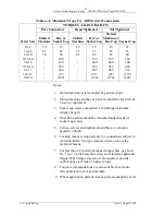
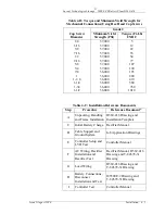
6. All bolts making electrical connections should be torqued
per the values in Table 4-A; all bolts for mechanical
connections should be torqued per values in Table 4-B.
Sequence of
Tasks
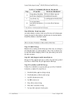
Table 4-C lists the drawings, manuals and other documentation
that are necessary to complete the following Sequence of Tasks.
Step A: Unpacking, Handling & Frame Installation:
Before opening the packaging, carefully inspect the outside, in
the presence of shipping personnel, for signs of damage. If
damaged, follow the shipping carrier's procedure for filing a
damage claim.
To ensure personnel safety and equipment protection use
appropriate equipment during handling of crates and uncrated
equipment. Use the equipment weights and dimensions, given in
Section 2, as a guideline for choosing material handling tools.
Move crated equipment to an area with adequate space and tools
for unpacking and handling.
Carefully open the packaging to verify that the contents are
complete and undamaged. If the equipment must be returned, it
should be repacked in the original shipping crate.
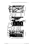
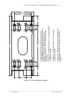
Locate, shim and anchor the framework(s). Figure 4-2 shows
typical floor mounting details for concrete floors. Other types of
floor construction may require other mounting methods. Holes
can be located using Figure 4-3. For multi-bay plants and for
plants in aisle line-ups with compatible framework, frames may
be tied together for extra rigidity. Three junction plates and
screws are provided with each framework for this purpose.
Assembly details for linking a multi-bay arrangement are
included in the H569-416 drawing provided with the battery
plant.


