Lucent Technologies Lineage 2000® Battery Distribution Fuse Bay (BDFB)
3 - 10 Product Description
Issue 4 March 1998
Load Bus
Arrangements
The bus bars used in the BDFB are sized to provide a 600 ampere
current carrying capacity for each load bus. A load bus is defined
as one or more fuse panels protected by a single circuit breaker
or fuse at the battery plant. Cable from the battery plant is
terminated at the top of the cabinet for top load feed or the
bottom of the cabinet for bottom feed. Cables are terminated to
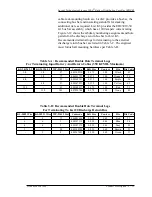
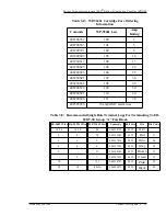
each load bus on two sets of 3/8 inch studs with 1.00 inch
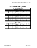
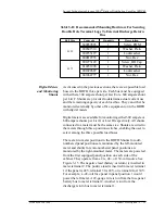
centers. Table 3-A lists recommended terminal lugs for different
cable sizes. Note that the largest cable that can be terminated is
350 KCMIL. Lists 11 thru 16 provide bus bar assemblies that
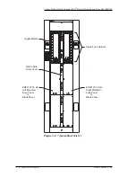
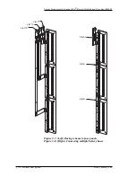
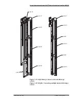
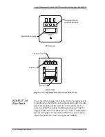
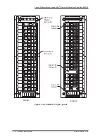
connect the input cabling to each fuse panel. Figure 3-7 shows
this busing arrangement on one side of the BDFB. Battery is
bused across a load monitoring shunt to each fuse panel.
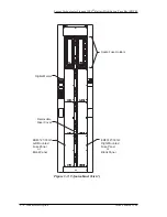
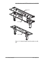
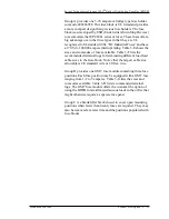
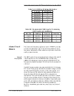
If fewer load buses are required, it is possible to connect fuse
panel battery buses together using a List A bus bar link. This
feature is shown on Figure 3-8. This may be desirable for two or
four load BDFB applications where more than twenty fuse
positions are required for a single load. Only fuse panels
mounted above or below one another may be connected, i.e. fuse
panels mounted on the left side of the cabinet cannot be joined
to fuse panels mounted on the right side of the cabinet. For
example, if positions one, three and five are linked together as
shown in Figure 3-8, one List 11 would be ordered for busing to
panel position 1 and two List A's for linking panels 5 to 3 and 3
to 1. Remember that the 600 ampere capacity per load bus
applies even if multiple fuse panels are connected together.
The 9 foot cabinet has two additional fuse panel positions. Since
a maximum of six separate load buses are possible, fuse panel
positions 7 and 8 can only be used as growth panels for loads
associated with fuse panels 5 and 6, i.e. positions 7 and 8 must
be linked using the List A bus bars to fuse panels 5 and 6
respectively. This is important for planning engineers to
remember for six-load BDFB applications where there is a
potential for one or two of the load buses to require more than
twenty fuse positions. These loads should be located in panel
positions 5 and 6.
NOTICE:
Equip fuse panels starting at panel position 1 to eliminate
possible cable congestion when installing additional fuse
panels in the field


