


Lucent Technologies Lineage 2000® Battery Distribution Fuse Bay (BDFB)
3 - 14 Product Description
Issue 4 March 1998
Discharge
Return Bus
Options
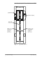
Two optional discharge return bus options are available for
terminating fuse return leads: (1) Bus bar returns located in the
BDFB or (2) A return bus located outside the BDFB on a cable
rack.
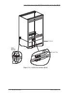
The first option involves a bus bar arrangement similar to the
battery bus connection scheme discussed in the previous section.
Discharge return cable from the battery plant is terminated at the
top (or bottom) of the cabinet adjacent to the battery input
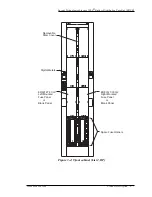
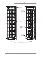
cabling. Lists 21-26 provide bus bar assemblies to connect the
battery plant discharge return cabling to List 20 bus bars
mounted on each fuse panel adjacent to the fuse blocks. This
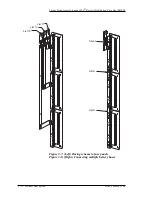
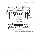
option is shown in Figure 3-9 for one side of the BDFB. It offers
the advantage of paired leads directly from the fuse and
eliminates the need for identification tags on each return lead.
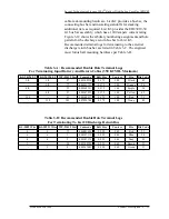
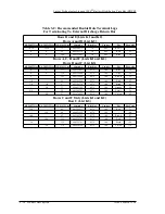
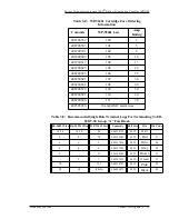
The discharge return bus is designed for terminating 1/4 inch
double hole terminal lugs. See Table 3-B. All terminal lug
mounting hardware is furnished.
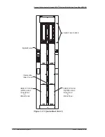
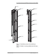
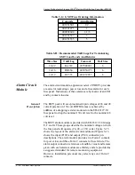
When the internal discharge return option is selected, a List 20
bus bar should be ordered for every fuse panel. However, there
is seldom a need to run individual discharge return leads back to
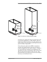
the battery plant. A more common practice is to connect multiple
discharge return buses together as shown in Figure 3-10 with
only one set of leads cabled back to the battery plant. When
multiple discharge return buses are connected together, a List B
bus bar link should be ordered. Only units mounted above or
below each other may be connected, i.e., panels mounted on the
left side of the cabinet cannot be connected to panels mounted on
the right side of the cabinet. For example, if positions 1, 3 and 5
are linked together as shown in Figure 3-9, order three List 20
discharge return bus bars, one List 21 for panel position 1 and
two List B bus bar links.
The drawback to this cabling scheme is that you are limited to
600 amperes capacity due to the size of the bus bars. A second
concern is the potential cable congestion resulting from twice
the number of leads in the BDFB. For these reasons, the internal
discharge return option is recommended only for applications
with smaller ultimate capacities. For most applications, the
external return bus option is recommended.
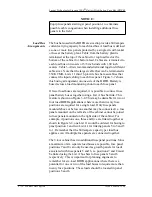
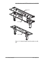
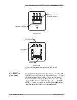
The external discharge return bus bar options are shown in
Figure 3-11. The external bus is mounted on a standard 15 or 20
inch ladder type cable rack. Lists K1 and K2 are rated for 2400
amperes of current. List K1 provides the first bus bar and the