


Lucent Technologies Lineage 2000® Battery Distribution Fuse Bay (BDFB)
3 - 24 Product Description
Issue 4 March 1998
Alarm Circuit
Module
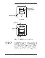
The alarm circuit module, apparatus code A-CP/BEP1, provides
a means for indicating a power loss and a fuse alarm for each
fuse panel. Indications of these alarms are by means of an LED
and by contact closures.
General
Description
The BEP1 pack will accept nominal input voltages of 24 and 48
volts. Operation in 130 volt BDFB frames is achieved by
addition of a dropping resistor mounted on the ED-83127-30
fuse panel to drop the nominal 130 volt level to the nominal 48
volt level.
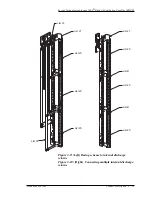
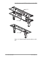
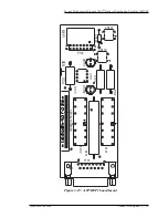
The BEP1 alarm module is provided with ED-83127-30 Groups
E, F and G. These groups describe the nominal voltage at which
the fuse panel will operate (24, 48, or 130 volts). Figure 3-15
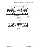
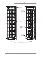
shows the layout of the alarm circuit module and Figure 3-16
shows the input (P102) and output (P101) connector pin
descriptions. The alarm module provides two Form C contacts
for power loss and three Form C contacts for fuse failure. The
alarm output connector references of audible, visual and remote
given with each alarm module are arbitrary and are provided as
a suggested standard for remote monitoring equipment.
However, installation personnel may select any set of Form C
contacts.
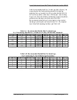
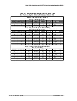
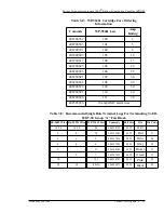
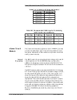
Table 3-G: GMT Fuse Ordering Information
Comcode
Amp Rating
401231501
1/2
401841473
1
400994604
1-1/3
401231527
3
401231535
5
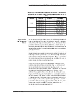
Table 3-H: Recommended T&B Lugs For Terminating
GMT Load Leads And Returns
Wire Size
T&B Lug
Comcode
Bolt Size
18-22
RA333
997588891
6
14-16
RB854
403950975
6
10-12
RC333
401437033
6


