

Lucent Technologies Lineage 2000® Battery Distribution Fuse Bay (BDFB)
Issue 4 March 1998
List of Figures - 1
List of Figures
Figure 1-1: J85568C-1 Battery Distribution Fuse Bay
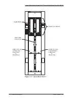
Figure 3-1: 7-foot cabinet (List 1)
Figure 3-2: 7-foot cabinet (List 1, BF)
Figure 3-3: 9-foot cabinet (List 2)
Figure 3-4: 9-foot cabinet (List 2, BF)
Figure 3-5: 2-1/2-foot extension cabinet
Figure 3-6: 2 foot or 4-1/2 foot extension cabinet
Figure 3-7: (Left) Busing scheme to fuse panels
Figure 3-8: (Right) Connecting multiple battery
buses
Figure 3-9: (Left) Busing scheme to internal discharge
returns
Figure 3-10: (Right) Connecting multiple internal
discharge returns
Figure 3-11: External discharge return bus options on
Figure 3-12: Bus bar hole pattern and numbering schemes 3 -
Figure 3-13: Digital meters (front and back views)
Figure 3-14: ED83127-30 fuse panels
Figure 3-15: A-CP/BEP1 board layout
Figure 3-16 : A-CP/BEP1 input/output connections
(alarm module with no power is in “normal” state) 3 - 30