Lucent Technologies Lineage 2000® Battery Distribution Fuse Bay (BDFB)
3 - 26 Product Description
Issue 4 March 1998
Frame Alarm
In addition to the individual panel alarm indicators, there is also
a frame alarm lamp at the top of the bay. This frame alarm lights
when power is lost to a fuse panel or there is a fuse alarm. Power
for lighting the frame lamp is brought from the battery plant on
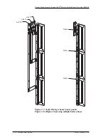
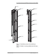
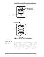
an auxiliary battery supply (ABS) lead. Figure 3-17 shows the
frame alarm and ABS termination points at the top of the
cabinet. When ABS is from a positive ground battery plant, it is
brought into the BDFB on terminal E3. This signal is daisy
chained through all the circuit modules. A fuse failure or power
loss on a circuit module sends the ABS signal back up to the
frame lamp socket. The ABS return lead back to the battery plant
is also connected to the frame alarm lamp via terminal E4 to
complete the circuit.
In some installations, the use of a ABS lead from the battery
plant may not be available or desirable. An alternative alarming
method substitutes power from a load bus for ABS. A 22-gauge
wire may be run from the battery bus of fuse panel number 1 to
terminal E3. The return lead from the frame lamp via terminal 4
would go to the discharge return bus located on the cable rack.
The obvious consequence of this option is if power is lost to fuse
panel number 1, the frame alarm will not light.
Monitoring
Multiple Alarm
Modules for
Negative Plants
Fuse Alarm
In most BDFB applications, customers require remote
monitoring of a frame fuse alarm only and not individual load
buses. Therefore, fuse alarms on multiple packs may be
connected so that the remote fuse alarm signal on one pack can
be operated from the other packs. This daisy chain is factory
wired so that frame fuse alarm may be monitored from the
position 1 alarm module. A fuse alarm on any pack will cause
current flow through opto-isolator U101 causing it to turn on and
apply voltage to P102 pins 4 and 5. Pins 4 or 5 are alternately
connected from pack to pack providing a common fuse alarm
output signal. The position 1 alarm module monitors the other
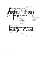
packs by connecting its P102 pin 1 fuse alarm input to P102 pin
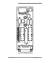
4 of the position 2 alarm module. See Figure 3-18. Thus voltage
from any pack with an active fuse alarm will cause K102 of the
position 1 pack to be operated via P102 pin 1, causing an alarm
on its P101 contacts. This feature is intended to provide a local
visual indication of a fuse alarm (DS102 of the pack with the
fuse alarm) and remote monitoring of the Form C contacts of a

