


Lucent Technologies Lineage 2000® Battery Distribution Fuse Bay (BDFB)
4 - 8 Installation
Issue 4 March 1998
Discharge return buses located in the BDFB are also equipped
with a C.O. ground termination point. Lists 21-26 provide bus
bar assemblies for busing battery to each fuse panel. Discharge
return cabling from the battery plant is terminated to these
assemblies at the top (or bottom) of the cabinet. C.O. ground
termination is made adjacent to the battery return cabling as
shown in Figure 4-4.
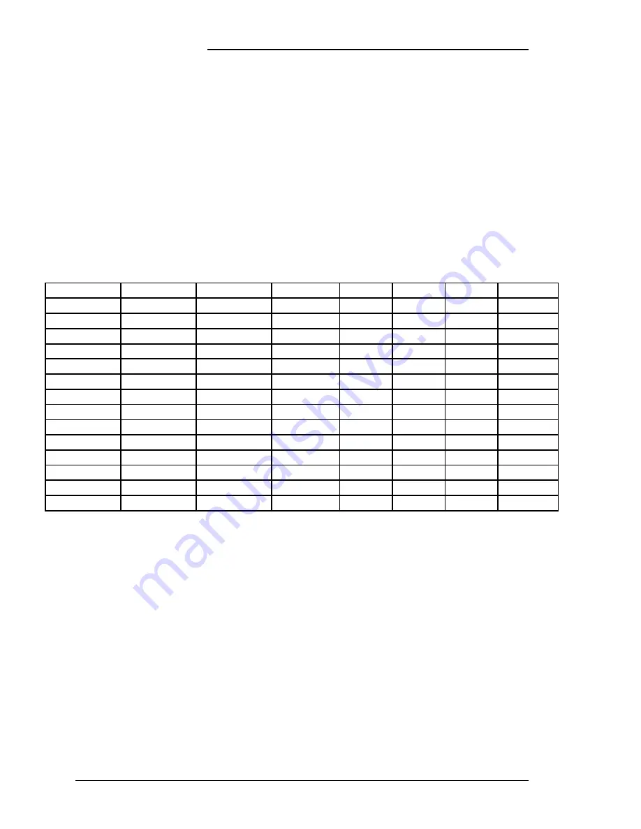
All C.O. ground connections accommodate 3/8 inch double hole
terminal lugs on 1.00 inch centers. Wire size is determined by
engineering based on local office requirements. Table 4-C lists
some recommended terminal lugs
Digital Meters
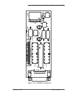
The BDFB has two meter positions, left mounted and right
mounted. Load monitoring shunts are wired to the meters
through three position switches enabling the user to select
between the three possible load buses on each side of the cabinet.
Switch positions are wired from left to right beginning with the
lowest numbered panel position. Panel position 1 is monitored
from the left meter and its left switch position. Panel position 2
is monitored from the right meter and its left switch position.
Refer again to Figure 3-13.
Table 4-C: Recommended Double Hole Terminal Lugs For Central Office Grounds
KS-5482 Wire KS-20921 Wire WP-91412 List
C
OMCODE
Bolt Size
Centers
Die
Die Code
6
6
111
406332841
0.375
1.00
Blue
24
4
4
116
406332940
0.375
1.00
Grey
29
2
-
121
406338665
0.375
1.00
Brown
33
1/0
-
56
405348228
0.375
1.00
Pink
42
2/0
1/0
57
405348236
0.375
1.00
Black
45
-
2/0
77
406021725
0.375
1.00
Orange
50
4/0
-
59
405348251
0.375
1.00
Purple
54
-
4/0
27
405347923
0.375
1.00
Yellow
62
350
-
61
405348277
0.375
1.00
Red
71
-
350
86
406021915
0.375
1.00
-
80
500
-
63
405348293
0.375
1.00
Brown
87
-
500
165
406434241
0.375
1.00
Pink
99
750
-
135
406335141
0.375
1.00
Black
106
-
750
170
406434290
0.375
1.00
Yellow
115


