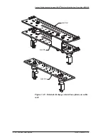

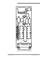


Lucent Technologies Lineage 2000® Battery Distribution Fuse Bay (BDFB)
3 - 30 Product Description
Issue 4 March 1998
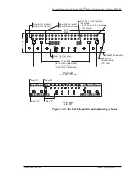
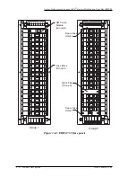
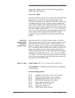
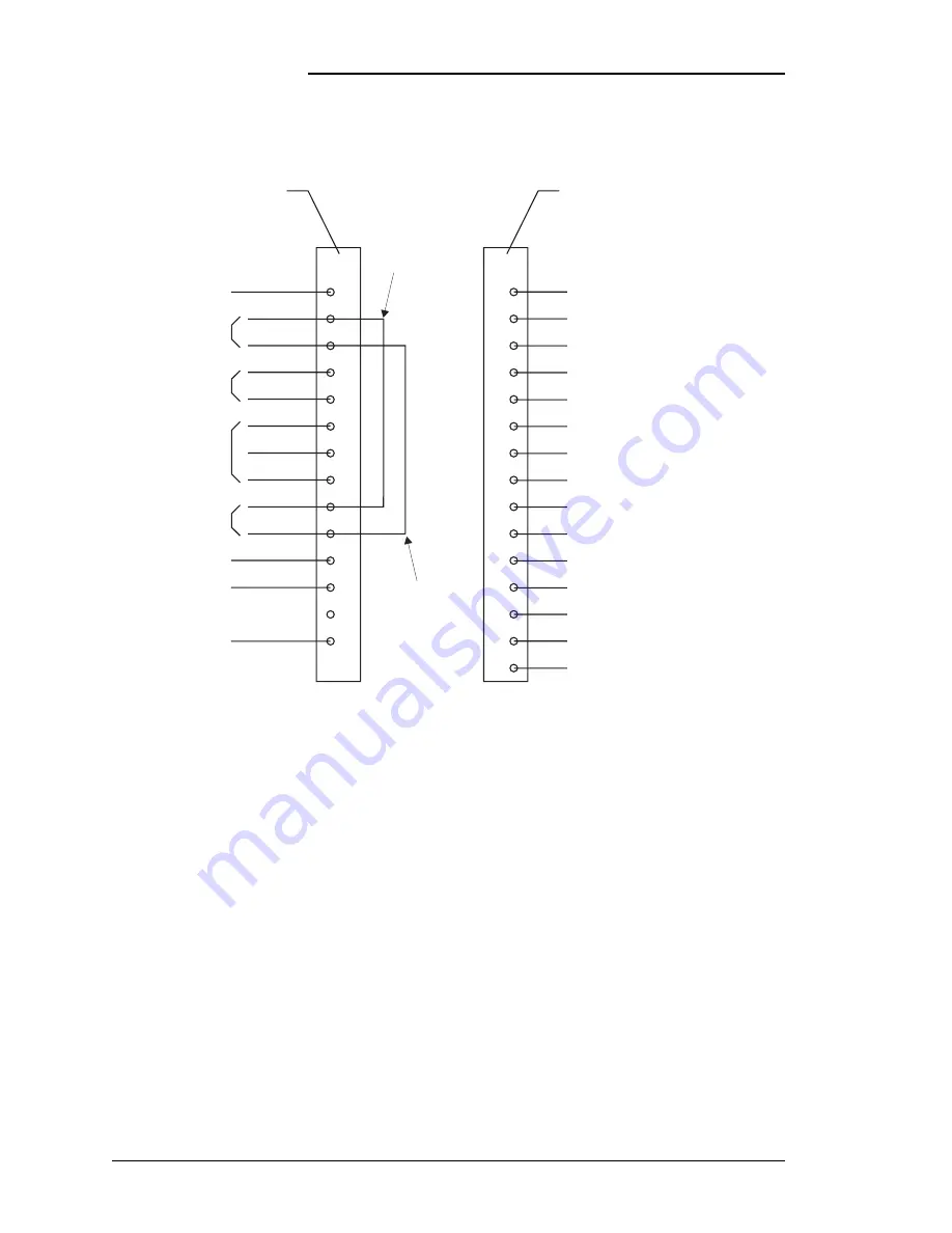
Figure 3-16 : A-CP/BEP1 input/output connections (alarm
module with no power is in “normal” state)
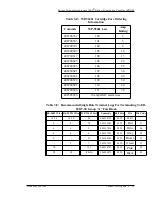
K101-4
K101-6
K101-13
K101-11
K102-6
K102-5
K102-11
K102-13
K101-8
K101-9
K102-7
K102-3
K102-4
K102-8
K102-9
C1
NC1
C2
NC2
NC1
NC2
NC3
C3
NO1
NO2
NO2
C2
C1
NO1
NO3
Power Loss (Aud)
Power Loss (Aud)
Power Loss (Vis / Remote)
Power Loss (Vis / Remote)
FAJ (Aud)
FAJ (Vis)
FAJ (Remote)
FAJ (Remote)
Power Loss (Aud)
Power Loss (Vis / Remote)
FAJ (Vis)
FAJ (Vis)
FAJ (Aud)
FAJ (Aud)
FAJ (Remote)
1
2
3
4
5
6
7
8
9
10
11
12
13
14
1
2
3
4
5
6
7
8
9
10
11
12
13
14
15
Fuse Alarm Signal Input
To Succeeding BEP1
Fuse Alarm
Signal Output
PWR (48V / 130V / 140V)
FAJ (24V)
FAJ (48V / 130V / 140V)
From Preceeding BEP1
or Frame Fuse Alarm
PWR (24V)
From Preceeding BEP1
or to External RTN Bus
To Succeeding BEP1
(W-Y)
(W-S)
(W-BL)
(W-BL)
(BL)
(Y)
(Y)
(W-Y)
(W-S)
(BL)
(BR)
(BR)
Pins 3 and 10
provide ABS to
each circuit pack.
Pins 2 and 9
send ABS to
light Frame Alarm.
P102
P101
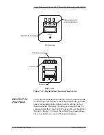
Panel Alarm Input Connector
Remote Alarm Output Connector


