background image

Lucent Technologies J85568E-1 Secondary DC Mini-Distribution Bay

Issue 4 January 1999 

Installation  5 - 9

Meter and 
Alarm 
Termination 
Panel

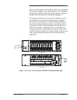
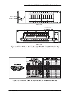
The top panel on the Mini-Distribution Bay is a meter and alarm 
termination panel. It consists of a digital meter and A/B switch 
wired to the current monitoring shunts of each load and an alarm 
termination circuit board. The purpose of the alarm termination 
board is to provide an easy access point for the installer to 
connect alarm monitoring equipment to the Mini-Distribution 
Bay. The alarm termination board is shown in Figure 5-6. It 
contains four 12-position screw type terminal blocks for 
monitoring the four sets of Form-C contacts of each fuse or 
circuit breaker panel (three for fuse or circuit breaker failure and 
one for power loss). Each fuse or circuit breaker panel may be 
monitored individually by connecting alarms to each of the four 
terminal blocks. The left terminal block is connected to fuse or 
circuit breaker panel #1, the next to fuse or circuit breaker panel 
#2, the third to fuse or circuit breaker panel #3, and the right 
terminal block to fuse or circuit breaker panel #4. Alarm wiring 
is connected to the terminal block by simply stripping the wire, 
placing the wire in the terminal, and tightening the screw. The 
recommended wire size is 22-26 gauge.

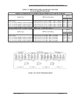
There are twelve DIP switches between each terminal block. 
Each DIP switch is associated with a terminal block position and 
is factory set to the open position. If a frame alarm is needed, 
simply close the DIP switches associated with that alarm. See 
Table 5-A. Alarm monitoring equipment requires either a 
closure on alarm or an open on alarm. When a frame alarm is 
needed as one of the alarms, simply close the DIP switch settings 
according to Table 5-A. Alarm wiring is connected at P201 
terminal block (C contact) and P204 terminal block (NO or NC 
contact). For example, if a frame fuse or circuit breaker alarm 
(visual) is required with closure on alarm, close positions 1 and 
3 on switches SW2, SW4, and SW6. Then connect a pair of 
alarm wires to P201 
pin 7 (C) and to P204 pin 9 (NO). It may be desirable to monitor 
for power loss to load A or B. Connect alarm wiring to pins 1 and 
either 2 or 3 (as required) of terminal block P201 or P202 to 
monitor load A. Connect a second pair of wires to either terminal 
block P203 or P204 to monitor load B. For a frame power loss 
alarm, set DIP switches and connect alarm wires as shown in 
Table 5-A.

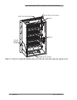
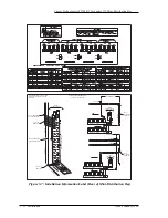
A label depicting the equipment layout, terminal lug options, 
and alarm termination board designations is located on the clear 
cover on the back of the unit to assist installation personnel. See 
Figure 5-7.

Summary of Contents for J85568E-1

Page 1: ...Lineage 2000 Secondary DC Distribution Bay Mini Distribution Bay J85568E 1 Product Manual Select Code 157 005 102 Comcode 107098840 Issue 4 January 1999 1999 Lucent Technologies...

Page 2: ......

Page 3: ...logies Lineage 2000 Secondary DC Distribution Bay Mini Distribution Bay Notice Every effort was made to ensure that the information in this document was complete and accurate at the time of printing H...

Page 4: ......

Page 5: ...ice 1 2 2 Product Description Overview 2 1 Features 2 1 Physical Specifications 2 2 3 Ordering Information List Structure 3 1 Terminal Lugs 3 2 Bay Extenders 3 4 Sample Order 3 4 Documentation 3 4 4 S...

Page 6: ...Technologies J85568E 1 Secondary DC Mini Distribution Bay 2 Table of Contents Issue 4 January 1999 Frame Ground 5 6 Fuse or Circuit Breaker Panel 5 6 Meter and Alarm Termination Panel 5 9 6 Product Wa...

Page 7: ...1 Typical Floor Mounting Detail 5 3 Figure 5 2 Floor Mounting Template 5 3 Figure 5 3 Rear View of Mini Distribution Bay and A B Load Connections four fuse panels shown 5 4 Figure 5 4A List C Fuse Pan...

Page 8: ......

Page 9: ...erminating Load Cables 750KCMIL Maximum 3 3 Table 3 C Recommended Double Hole Terminal Lugs for Terminating to Discharge Return Bus or Frame Ground 3 3 Table 3 D Recommended Single Hole 90 Terminal Lu...

Page 10: ......

Page 11: ...Bay is a secondary fuse distribution center for dc power delivered from a central office battery plant to the using equipment When floor space is minimized the Mini Bay provides a cost effective solut...

Page 12: ...Lucent Technologies customers is available around the world during the normal product warranty period and also while specific contractual agreements extend this service For customers in the United Sta...

Page 13: ...Lucent Technologies J85568E 1 Secondary DC Mini Distribution Bay Issue 4 January 1999 Introduction 1 3 conformance issues prior to customer ownership contact your local customer service...

Page 14: ......

Page 15: ...rcuit breakers This Mini Distribution Bay is designed to mount in a 23 inch relay rack See Figure 2 1 It can also be factory installed in an ED8C800 50 7 framework See Figure 2 2 If the Mini Distribut...

Page 16: ...arm Green LED Power On GMT alarm fuse per fuse block Remote alarm indication 3 Form C fuse or circuit breaker alarm contacts per panel 1 Form C power loss alarm contact per panel Switch selectable fra...

Page 17: ...8E 1 Secondary DC Mini Distribution Bay Issue 4 January 1999 Product Description 2 3 Figure 2 1 J85568E 1 Mini Distribution Bay four fuse panels shown Panel Position 1 2 3 4 33 00 12 00 23 33 22 33 Ce...

Page 18: ...DC Mini Distribution Bay 2 4 Product Description Issue 4 January 1999 Figure 2 2 J85568E 1 Mini Distribution Bay Factory Installed in ED8C800 50 G5 Framework four fuse panels shown 84 00 25 94 ED8C800...

Page 19: ...on Bay in a ED8C800 50 framework as shown in Figure 2 2 Table 3 A J85568E 1 Mini Distribution Bay Ordering Information Description List Assembly wiring and equipment for one 33 inch 48V battery distri...

Page 20: ...30 Group 14 to monitor the 300A shunts associated with each load 4 This Mini Distribution Bay is recommended for top load feed applications When bottom load feed is required the J85568C 1 bay is reco...

Page 21: ...Black Orange Purple Yellow Red 80 Brown Pink Black Yellow Table 3 C Recommended Double Hole Terminal Lugs for Terminating to Discharge Return Bus or Frame Ground KS 5482 Wire KS 20921 Wire WP 91412 Li...

Page 22: ...ciated with the Mini Distribution Bay J85568E 1 Assembly Drawing SD 83178 01 Schematic T 83178 30 Wiring Diagram Table 3 E Recommended Single Hole Terminal Lugs for Terminating to Circuit Breakers KS...

Page 23: ...Technologies J85568E 1 Secondary DC Mini Distribution Bay Issue 4 January 1999 Ordering Information 3 5 ED 83127 30 Fuse or Circuit Breaker Panel 157 005 102 J85568E 1 Mini Distribution Bay Product M...

Page 24: ......

Page 25: ...restricted access areas dedicated equipment rooms equipment closets or the like in accordance with articles 110 16 110 17 and 110 18 of the U S National Electric Code NEC ANSI NFPA No 70 and pursuant...

Page 26: ...he necessary knowledge and practical experience with electrical equipment and who understand the hazards that can arise when working on this type of equipment Because of the hazardous energy supplied...

Page 27: ...ements and Safety Symbols The symbols may sometimes be accompanied by some type of statement e g Hazardous voltage energy inside Risk of injury This unit must be accessed only by qualified personnel T...

Page 28: ...nsulated metal objects Follow safety precautions This symbol is used to identify the presence of a hot surface It may also be accompanied by a statement explaining the hazard A symbol like this with a...

Page 29: ...circuit packs to clean them unless you and the circuit pack are at the same ground potential Observe warning labels on bags and cartons Whenever possible do not remove circuit packs from antistatic b...

Page 30: ...Lucent Technologies J85568E 1 Secondary DC Mini Distribution Bay 4 6 Safety Issue 4 January 1999 Minimize electrostatic discharge when handling circuit modules...

Page 31: ...Lucent Technologies J85568E 1 Secondary DC Mini Distribution Bay Issue 4 January 1999 Safety 7...

Page 32: ...Lucent Technologies J85568E 1 Secondary DC Mini Distribution Bay 8 Safety Issue 4 January 1999...

Page 33: ...uding jeweler s screwdriver electrical tape wire cutters and strippers for 8 AWG to 750 MCM Common mechanic s hand tools including flat blade screwdriver socket and torque wrenches for 1 4 inch and 3...

Page 34: ...washers and washers for terminating distribution cabling 2 sets of 1 4 20 screws lockwashers and washers for terminating frame ground 2 847257862 bus bars for connecting bottom load feeds Cover plates...

Page 35: ...Down Plate Floor Anchor Bolt Hold Down Washer Floor Covering Note Use 3 4 Inch Drill for Floor Anchor Bolts The Required Minimum Drill Depth is 4 Inches 1 1 1 1 2 2 2 2 25 94 18 50 1 24 3 72 1 20 1 2...

Page 36: ...tribution Bay 5 4 Installation Issue 4 January 1999 Figure 5 3 Rear View of Mini Distribution Bay and A B Load Connections four fuse panels shown Alarm Termination Board Product Manual Holder Bus A Fr...

Page 37: ...Bay is equipped with a distribution return bus located along the left and bottom sides of the unit The bus bar has a 600 ampere current carrying capacity and is equipped with 1 4 inch studs on 0 625...

Page 38: ...circuit breaker panel has 12 circuit breaker positions and an alarm circuit module Circuit breaker sizes and ordering comcodes are listed on a label on the front of the Mini Distribution Bay See Figu...

Page 39: ...es to an alarm termination board located at the top of the Mini Distribution Bay This termination board provides a convenient point for installation to connect alarm monitoring systems Each set of con...

Page 40: ...ssue 4 January 1999 Figure 5 4B List D Circuit Breaker Panel for J85568E 1 Mini Distribution Bay Red LED Green LED Alarm Circuit Module BEP1 Front View Rear View EQUIPMENT TYPE FUSE CB AMPS FUSE CB AL...

Page 41: ...he wire in the terminal and tightening the screw The recommended wire size is 22 26 gauge There are twelve DIP switches between each terminal block Each DIP switch is associated with a terminal block...

Page 42: ...r circuit breaker Alarm Audible Strap from P202 position 4 to P202 position 5 Strap from P204 position 4 to P204 position 5 Fuse or circuit breaker Alarm Visual Strap from P202 position 7 to P202 posi...

Page 43: ...W3 and SW5 Close Positions 4 and 6 on SW1 SW3 and SW5 Close Positions 1 and 3 on SW2 SW4 and SW6 Close Positions 4 and 6 on SW2 SW4 and SW6 pin 1 pin 4 pin 7 pin 10 pin 2 pin 6 pin 9 pin 12 Open on Al...

Page 44: ...RIATE TIE ALL TO BAR TIES BAR TIE BAR TIE B A R T I E TIE TO CROSS BARS WHEN APPROPRIATE TIE ALL TO BAR TIES RECOMMENDED CABLING PLAN FOR FULLY LOADED PLANT DISCHARGE RETURN BUS TIE DOWN 5 5 FROM WALL...

Page 45: ...arranties given to Seller by its Vendor of such Vendor Items such assignment to be effective upon Customer s acceptance of such Vendor Items With respect to Vendor items recommended by Seller in its s...

Page 46: ...readily returnable for repair whether or not installed by Seller Seller at its option may repair the cable and Wire Products at Customer s site D If Seller has elected to repair or replace a defective...

Page 47: ...contractors caused by any of the following modifications misuse neglect accident or abuse improper wiring repairing splicing alteration installation storage or maintenance use in a manner not in accor...

Page 48: ......

Reviews: