Lucent Technologies Lineage
®
2000 100A Ferroresonant Rectifier J85503A-1
8 - 10 Spare Parts and Replacement Procedures
Issue 6 October 1998
•
All removal and replacement procedures are easier to
perform on bay-mounted rectifiers that have been removed
from the bay.
•
Most component removals are straightforward and obvious.
Therefore, these procedures can be used as a guide by
qualified service personnel, rather than as step-by-step
procedures. For example, you may prefer to remove a part
not called for in order to make more room for access to a
component being replaced.
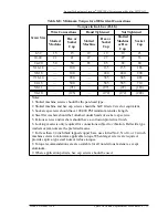
Table 8-D and Table 8-E provide the reassembly torquing
requirements for the electrical and mechanical connections in
the rectifier. Use these values unless otherwise directed in the
procedures.
Table 8-D: Torque and Minimum Yield Strength for
Mechanical Connections (Using Hex Head Cap Screws)
Cap Screw
Diameter (inches)
Min. Yield
Strength (PSI)
Torque (Ft-Lb)
UNC
1/4
57,000
6
5/16
57,000
12
3/8
57,000
22
7/16
57,000
35
1/2
57,000
54
9/16
57,000
77
5/8
57,000
107
3/4
57,000
190
7/8
36,000
193
1
36,000
290
1-1/8
36,000
410
1-1/4
36,000
580
1-3/8
36,000
760
1-1/2
36,000
1010

