Lucent Technologies Lineage
®
2000 100A Ferroresonant Rectifier J85503A-1
2 - 12 Product Description
Issue 6 October 1998
•
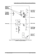
The Reg test jacks allow for measuring the plant output
voltage at the points where the remote sense leads are
connected. This measurement is accurate only when the
remote sense leads are connected.
•
The 1/2 Amp +V and –V alarm fuses protect the voltage
sense leads to the rectifier control and regulation circuits.
•
The DC Output circuit breaker protects the plant from
rectifier malfunction and excessive current, and may be
used to disconnect the rectifier from the battery. An Output
circuit breaker alarm issues and the RFA LED lights when
the circuit breaker trips.
Alarm and
Control Flow
The J85503A-1, 100-ampere rectifier is typically installed in a
battery plant that is monitored and controlled by a Lucent
Technologies Lineage
®
2000 controller. The rectifier generates
various monitoring and alarm signals and, in this type of
installation, sends them to the controller for processing and
subsequent action. The action may be local or remote alarm
indications or control signals fed back to the rectifier. Refer to
the various Lineage
®
2000 controller product manuals for a
description of rectifier signal processing and resultant action.
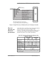
Figure 2-6 shows the typical signal flow between a rectifier and
a Lucent Technologies controller. The control signals and
alarms enter and leave the rectifier via the control circuit module
CM2. The Lineage
®
2000 family of plant controllers also uses
replaceable circuit modules which give flexibility to battery
plant design.

