Lucent Technologies Lineage
®
2000 100A Ferroresonant Rectifier J85503A-1
Issue 6 October 1998
Installation 5 - 15
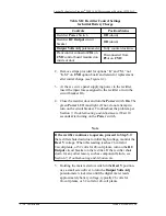
240). The second is to rewire the auxiliary transformer (T3)
input by reconnecting jumpers on the fast-on terminal strip
mounted on T3.
Connecting the Three Alternate AC Leads:
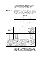
1. Remove the relay shield to expose the K1 contactor and
the T3 terminal strip. Remove the three wires from the K1
contactor and note that they are marked according to the ac
voltage to be converted from, (3, 5, and 1 to convert from
240 Vac, or 2, 4, and 2 to convert from 208 Vac). See the
third column of the table.
2. Insulate the ends of the wires removed from K1 with either
UL and CSA approved tape or tubing.
3. Remove the three alternate voltage wires from the bundle
and verify that the wires are marked according to the ac
voltage to be converted to, (2, 4, and 2 for 208 Vac, or 3, 5,
and 1 for 240 Vac). Pull these wires up to K1.
4. Push the wires removed from K1 in Step 1 down to where
the alternate voltage wires were and bundle them.
5. Install the three alternate voltage wires to the K1 contactor
as specified in the second column of the table.
Jumper Connections on Fast-On Terminal Strip:
6. Note that permanent connections to the terminal strip are
on contacts A1, B1, and C1. The yellow jumper wires
connected to these same terminals go to the C2, A2, and
B2 terminals for a 208 Vac input, and to the C3, A3, and
B3 terminals for a 240 Vac input. Therefore, a conversion
involves moving each of the three jumpers one terminal in
either direction.
7. Make the terminal strip jumper connections for the desired
input line voltage per the fourth column in the table.
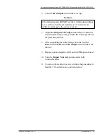
8. Replace the relay shield removed in Step 1.
Converting DC
Output Polarity
This section gives conversion procedures for the dc output
polarity of the Lineage
®
2000 J85503A-1 ±24-volt rectifier. Use
the section “Negative Output (Positive Ground) to Positive

