Lucent Technologies Lineage
®
2000 100A Ferroresonant Rectifier J85503A-1
5 - 16 Installation
Issue 6 October 1998
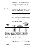
Output (Negative Ground)” to convert to a positive output
(negative ground) system, and use the section “Positive Output
(Negative Ground) to Negative Output (Positive Ground)” to
convert to a negative output (positive ground) system.
Negative Output
(Positive
Ground) to
Positive Output
(Negative
Ground)
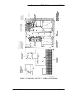
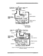
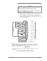
In Figure 5-4, rectifier wiring appears as in the upper drawing
before the work is started, and appears as in the lower drawing
upon completion of the work. Save the washers and nuts that are
removed for later use.
1. Remove both ends of Cable A from terminal A and
terminal D. Save the cable.
2. Remove the end of Cable B from terminal B. Reconnect
this end to terminal A.
3. Remove the end of Cable C from terminal C. Reconnect
this end to terminal D.
4. Install Cable A, removed in Step 1, between terminal B
and terminal C. Cable A may have to be positioned other
than the way shown in order to reach between B and
terminal C.
5. The wiring should now appear as in the lower drawing of
Figure 5-4. Indicate, by stamping on the inside of the
rectifier front panel, that the rectifier is now a positive
output (negative ground) system (List B).
Positive Output
(Negative
Ground) to
Negative Output
(Positive Ground)
DANGER
This procedure MUST be performed ONLY on a rectifier
completely disconnected from the battery and plant bus, AND
with ac power disconnected at the ac service panel.
DANGER
This procedure MUST be performed ONLY on a rectifier
completely disconnected from the battery and plant bus, AND
with ac power disconnected at the ac service panel.


