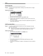
PSU at a Polled Site
Issue 1 January 1997
7-3
d.
Proceed to Configuring the Unit.
4.
For a direct connection, connect the PSU-to-PC cable from the PSU “DCE OUTPUT”
port to the serial port on the PC used for collecting SMDR data from this site.
Configuring the Unit
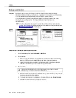
1. Turn the PSU upside down to
configure the DIP switches:
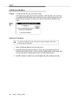
2. Match communications system SMDR
port values on SWITCH A:
O
N
1 2 3 4 5 6 7 8
O
N
1 2 3 4 5 6 7 8
O
N
1 2 3 4 5 6 7 8
OUTPUT PORT—SWITCH B>
CONFIGURATION—SWITCH C>
DIP Switches
INPUT PORT—SWITCH A>
Baud Rate (A-1, A-2, A-3)
OFF-ON-ON = 1200
Word Length ( A-4)
ON = 8 bits
Parity (A-5 , A-6)
OFF-OFF = none
Flow control (A-7, A-8)
OFF-ON = Xon/Xoff
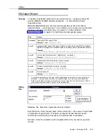
3.
Set output values to match modem or PC on SWITCH B:
Baud Rate*
(B-1, B-2, B-3)
OFF-OFF-OFF = 150
OFF-OFF-ON = 300
OFF-ON-OFF = 600
OFF-ON-ON = 1200
ON-OFF-OFF = 2400
ON-OFF-ON = 4800
ON-ON-OFF = 9600
ON-ON-ON = 19200
Direct/Modem Connection (B-8)
OFF = connected to PC by modem
ON = directly connected to PC
* If your modem's highest baud rate is not represented above, use the closest lower value (for example, on
a 14400-baud modem, set the baud rate to 9600).
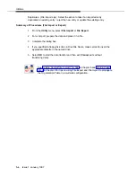
4.
Set these configuration values on SWITCH C:
PSU power loss mode (C-1)
OFF = Sleep
(keeps data for 10 to 40 days)
ON = Run
(collects calls
≤
2 hours, then goes to sleep)
Use/ignore Switch A settings (C-8)
ON = Use Switch A
(ignore MERLIN LEGEND Reporter
settings)
DO NOT TURN THIS SWITCH OFF.
If you do so, a poll by MERLIN LEGEND Reporter
will result in changing the PSU SMDR input port
settings, stopping call collection.
!


