Installation Tests
Clearing Alarms
...........................................................................................................................................................................................................................................................
4 - 7
Lucent Technologies - Proprietary
See notice on first page
365-372-327 R2.0
Issue 1, October 2003
............................................................................................................................................................................
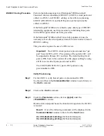
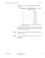
Step 8
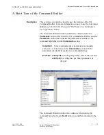
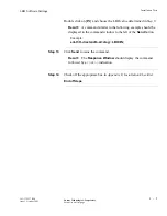
Click
Send
to issue the command.
Result:
The
Response Window
should display the command
followed by a
COMPLD
indication.
............................................................................................................................................................................
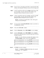
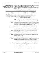
Step 9
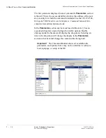
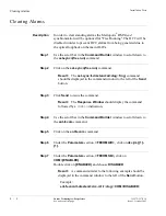
Under the
Parameters
section,
<FECOMAID>,
click on
dcc-{m}{1}-
{1}.
Double click on the
1
in {
m
}{
1
} and choose
2
.
............................................................................................................................................................................
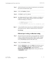
Step 10
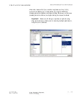
Under the
Parameters
section,
<FECOMSB>,
verify that
COM={DISABLED}.
Result:
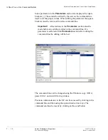
A command similar to the following example should be
displayed in the command window to the left of the
Send
button.
Example:
ent-fecom:lt-dmxtend:dcc-m2-1:ctag:::COM=DISABLED;
............................................................................................................................................................................
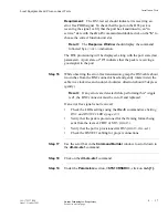
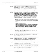
Step 11
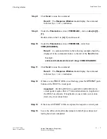
Click
Send
to issue the command.
Result:
The
Response Window
should display the command
followed by a
COMPLD
indication.
............................................................................................................................................................................
Step 12
If there are any
FAULT
LEDs on or flashing, press the
UPD/INIT
push
button on the SYSCTL circuit pack.
Important!
LNW16 (DS3/EC1) and LNW39 (DS1/DS3/16/3)
circuit packs require either a 75 ohm termination or a loopback at
the DSX-3 on all ports. If loopbacks are used, make sure to take
down any cross connections.
............................................................................................................................................................................
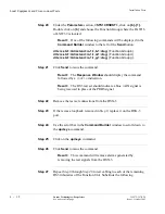
Step 13
If there are still
FAULT
LEDs on, replace the respective circuit pack.
............................................................................................................................................................................
Step 14
Leave the office alarm cable disconnected until all procedures and
testing have been completed.

