...........................................................................................................................................................................................................................................................
Operational Tests
Office Alarm Test
5 - 6
Lucent Technologies - Proprietary
See notice on first page
365-372-327 R2.0
Issue 1, October 2003
Procedure
Step 1
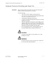
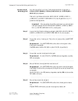
Connect the office alarm cable to
J13
(
ALM)
on the backplane of the
Metropolis
®
DMXtend shelf. If the shelf to be tested is part of a
multiple shelf bay arrangement, the office alarm cable connects to shelf
1.
............................................................................................................................................................................
Step 2
Verify that one of the function groups is equipped with LNW6/LNW7
(28DS1), LNW16 (12DS3/EC1) or LNW39 (DS1/DS3/16/3) circuit
packs.
............................................................................................................................................................................
Step 3
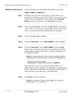
Establish a CIT session by following the procedure under Use of
WaveStar™ CIT Software (page 3-8) in Chapter 3, Software Download
and Circuit Pack Installation.
............................................................................................................................................................................
Step 4
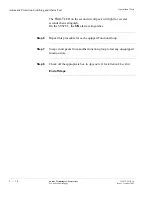
Use the scroll bar in the
Command Builder
window to scroll down to
the
ent-crs-sts1
command.
............................................................................................................................................................................
Step 5
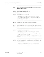
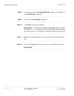
Click on the
ent-crs-sts1
command.
............................................................................................................................................................................
Step 6
Under the
Parameters
section,
<STS1CRSSRC>,
click on
m-1-{1}
.
............................................................................................................................................................................
Step 7
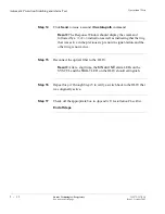
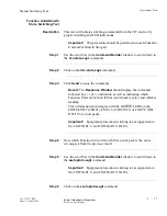
Under the
Parameters
section,
<STS1CRSDST>,
click on
{a}-{1}
.
Double click on
a
and choose the Function Group where the LNW6/
LNW7 (28DS1), LNW16 (12DS3/EC1) or LNW39 (DS1/DS3/16/3)
circuit pack is installed.
Result:
A command similar to the following example should be
displayed in the command window to the left of the
Send
button
Example for Function Group A:
ent-crs-sts1:
LT-DMXTEND
:m-1-1,a-1:1::2WAYPR;
This command creates a cross-connect to map all 28 DS1s of a
28DS1circuit pack or the first DS-3 of a 12DS3/EC1 for Function Unit
D or G or all 16 DS1s of the LNW39 circuit pack in Function Unit A-1
and/or A-2 slot(s) to the first STS-1 of the Main OLIUs.

