Operational Tests
TL1/X.25 Connection Test
...........................................................................................................................................................................................................................................................
5 - 2 7
Lucent Technologies - Proprietary
See notice on first page
365-372-327 R2.0
Issue 1, October 2003
............................................................................................................................................................................................................................................................
TL1/X.25 Connection Test
Description
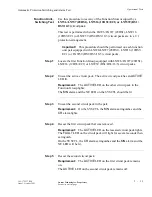
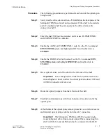
The following procedure will verify that the X.25 link between the
Metropolis
®
DMXtend shelf and the interfacing telemetry equipment
has been established. Performance of this test requires that the
interfacing telemetry equipment is operational and conditioned to
establish an X.25 connection with the Metropolis
®
DMXtend shelf.
Procedure
Step 1
Verify that the X.25 cable is properly connected to the
J19
(
X.25)
connector on the Metropolis
®
DMXtend backplane.
............................................................................................................................................................................
Step 2
Verify that the interfacing telemetry equipment is operational and
conditioned to established an X.25 connection with the Metropolis
®
DMXtend shelf
............................................................................................................................................................................
Step 3
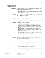
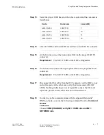
Use the scroll bar in the
Command Builder
window to scroll down to
the
rtrv-state-x25
command.
............................................................................................................................................................................
Step 4
Click on the
rtrv-state-x25
command.
............................................................................................................................................................................
Step 5
Click
Send
to issue the command.
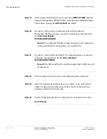
Result:
The Response Window should display the command
followed by a
COMPLD
indication as well as indicating that the GNE
is active and the state of the various pvc and svc connections is
either up or down in accordance with the provisioning of the
interfacing telemetry equipment.
............................................................................................................................................................................
Step 6
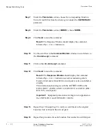
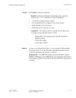
Check off the appropriate box in Appendix E, Installation Checklist.
...........................................................................................................................................................................
End of Steps

