...........................................................................................................................................................................................................................................................
Equipment and Cable Installation for Metropolis
®
DMXtend
Shelf Horizontal Bay Mount
DS1 Cable Installation
1 - 1 8
Lucent Technologies - Proprietary
See notice on first page
365-372-327 R2.0
Issue 1, October 2003
............................................................................................................................................................................................................................................................
DS1 Cable Installation
Description
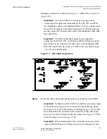
This section describes how to connect the DS1 transmission cables for
function group D or G, to the shelf, route the cables out of the bay and
connect the cables to the DSX. Perform this procedure if DS1 cables
are required.
Important!
When cabling the Metropolis
®
DMXtend to a DSX,
the DSX becomes an extension of the Metropolis
®
DMXtend
backplane connections. Thus the IN on the Metropolis
®
DMXtend
backplane connects to the IN of the DSX and the OUT of the
Metropolis
®
DMXtend backplane connects to the OUT of the DSX
respectively.
The cables are connectorized at the Metropolis
®
DMXtend end and
must be wire-wrapped at the DSX end. A total of two function groups
fully cabled will have 112 DS1 drop capacity when the higher density
DS1 circuit packs become available and are supported by the
Metropolis
®
DMXtend software.
Important!
The 112 DS1 figure does not include the 16 DS1 drop
available when using the LNW39 DS1/DS3/16/3 combo card in slot
A/B. Instructions for cabling slot A/B are provided in DS1 and DS3
Hybrid Cable Installation (page 1-39).
Important!
The connectorized cable end is grounded to the
Metropolis
®
DMXtend frame ground through the backplane. Lucent
recommends that the shield at both ends of the DS1 cable be
grounded. Ground at the DSX end per office requirements.
............................................................................................................................................................................
Procedure
Step 1
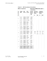
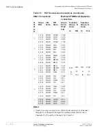
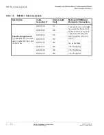
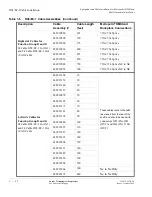
Refer to the engineering job specification. Obtain the DS1 cables per
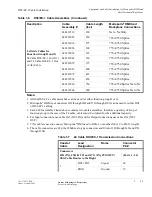
Table 1-4, DS1 Cable Assemblies (page 1-21) and note the function
group where each cable will be used. Label the cables, indicating bay,
shelf, function group (D or G) and direction (IN or OUT of the bay) at
each end.
............................................................................................................................................................................
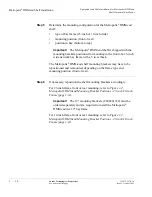
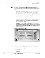
Step 2
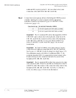
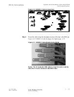
Connect the function group cables at the Metropolis
®
DMXtend end,
carefully matching the correct connector with the appropriate

