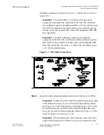
...........................................................................................................................................................................................................................................................
Equipment and Cable Installation for Metropolis
®
DMXtend
Shelf Horizontal Bay Mount
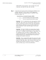
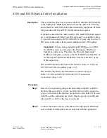
DS1 Cable Installation
1 - 2 4
Lucent Technologies - Proprietary
See notice on first page
365-372-327 R2.0
Issue 1, October 2003
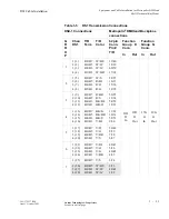
1
1 (29)
2 (30)
3 (31)
4 (32)
B8/B7
B6/B5
B4/B3
B2/B1
19/40
18/39
60/59
17/38
J2D
D
In
J4D
D
Out
J8G
G
In
J10G
G
Out
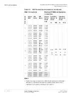
2
1 (33)
2 (34)
3 (35)
4 (36)
B8/B7
B6/B5
B4/B3
B2/B1
W/S
R/BL
R/O
R/G
58/57
16/37
15/36
14/35
3
1 (37)
2 (38)
3 (39)
4 (40)
B8/B7
B6/B5
B4/B3
B2/B1
R/BR
R/S
BK/BL
BK/O
56/55
13/34
54/53
12/33
4
1 (41)
2 (42)
3 (43)
4 (44)
B8/B7
B6/B5
B4/B3
B2/B1
BK/G
BK/BR
BK/S
Y/BL
11/32
10/31
52/51
9/30
5
1 (45)
2 (46)
3 (47)
4 (48)
B8/B7
B6/B5
B4/B3
B2/B1
Y/O
Y/G
Y/BR
Y/S
50/49
8/29
7/28
6/27
6
1 (49)
2 (50)
3 (51)
4 (52)
B8/B7
B6/B5
B4/B3
B2/B1
V/BL
V/O
V/G
V/BR
48/47
5/26
46/45
4/25
7
1 (53)
B8/B7
V/S
3/24
2 (54)
3 (55)
4 (56)
B6/B5
B4/B3
B2/B1
W/BL¹
W/O¹
W/G¹
2/23
44/43
1/22
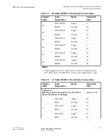
Notes:
1. Some wire colors are used twice. White binder cables are for Channel 1
through 25 or Channel 29 through 53 and blue binder cables are for
Channels 26, 27 and 28 or Channels 54, 55 and 56.
Table 1-5
DS1 Transmission Connections (Continued)
DSX-1 Connections
Metropolis
®
DMXtend Backplane
connections
G
R
O
U
P
Chan
DS1
T/R
Term
T/R
Color
62 pin
Conn.
Pin#
T/R
Function
Group D
Conn.
Function
Group G
Conn.
In
Out In
Out

