...........................................................................................................................................................................................................................................................
Powering and Initial Circuit Pack Installation for
Metropolis
®
DMXtend Shelf Horizontal Bay Mount
Initial Circuit Pack Installation
2 - 1 6
Lucent Technologies - Proprietary
See notice on first page
365-372-327 R2.0
Issue 1, October 2003
............................................................................................................................................................................
Step 8
Check off the appropriate box in Appendix E, Installation Checklist.
...........................................................................................................................................................................
End of Steps
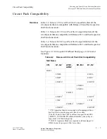
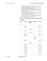
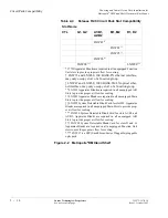
LNW16 (12DS3/EC1) &
LNW19 (48DS3/EC1) Low
Speed Installation
(Optional)
Follow this procedure only if installing LNW16 (12DS3/EC1) and the
LNW19 (48DS3/EC1) circuit packs into the Metropolis
®
DMXtend
shelf. The EC1 feature of the LNW16 will not be supported until R1.1
Step 1
Refer to the engineering job specification. Identify the proper function
group(s) where LNW16 (12DS3/EC1) or LNW19 (48DS3/EC1) will
be installed.
............................................................................................................................................................................
Step 2
Remove the LNW16 (12DS3/EC1) or LNW19 (48DS3/EC1) from the
packing material.
............................................................................................................................................................................
Step 3
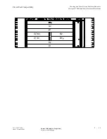
Place the circuit pack into the shelf (slot D1 or G1 as required). Do
NOT engage the circuit pack in the backplane connector.
............................................................................................................................................................................
Step 4
If a protection circuit pack is required, continue with the Step 5. If not,
install a 177D or LNW98 Apparatus Blank into the protection circuit
pack slot (D2 or G2 as required), then proceed to Step 7.
Important!
177D or LNW98 Apparatus Blanks are required in all
unused slots D and G to provide proper air flow for cooling.
............................................................................................................................................................................
Step 5
Remove the second LNW16 (12DS3/EC1) or LNW19 (48DS3/EC1)
from the packing material.
............................................................................................................................................................................
Step 6
Place the circuit pack into the shelf (slot D2 or G2 as required). Do
NOT engage the circuit pack in the backplane connector.
............................................................................................................................................................................
Step 7
Repeat Step 1 through Step 6 for each additional function group to be
equipped with LNW16 (12DS3/EC1) LNW19 (48DS3/EC1) circuit
packs.

