...........................................................................................................................................................................................................................................................
Installation Tests
Local Equipment and Cross-connect Tests
4 - 2 0
Lucent Technologies - Proprietary
See notice on first page
365-372-327 R2.0
Issue 1, October 2003
LNW71 (10/100-PL),
LNW66 (10/100T) (R1.1) TX
Ethernet cabling testing
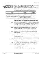
This procedure is to test the Ethernet 10/100 TX cabling from function
groups D and G to the RJ45 patch panel for use with the
LNW71 (10/100-PL), or the LNW66 (10/100T) (Supported in release
R1.1 and later).
The following cables are required to test the Ethernet cabling.
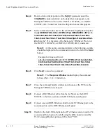
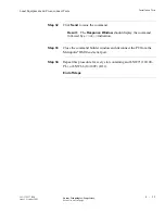
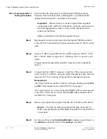
Ethernet port assignment verification testing.
Step 1
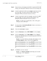
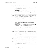
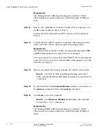
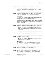
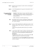
Connect the Front CIT cable between the PC and the CIT/RS 232 jack
of System Controller and login to the shelf using the serial connection
and the TL1/Command Builder options on WaveStar
TM
CIT.
............................................................................................................................................................................
Step 2
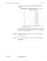
Identify the function groups that contain LNW71 (10/100-PL), or
LNW66 (10/100T) (R1.1) circuit packs with cabling for testing.
............................................................................................................................................................................
Step 3
Identify the RJ45 patch panel associated with the function groups
identified above.
............................................................................................................................................................................
Step 4
Connect the RJ45 cable from the first RJ45 on the patch panel to the
Ethernet port on your PC.
............................................................................................................................................................................
Step 5
Watch for the link LED to light on the PC’s Ethernet card or wait for 30
seconds and then disconnect the RJ45 cable from the patch panel.
............................................................................................................................................................................
Step 6
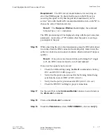
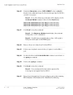
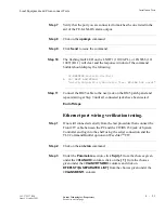
The Fault LED will start flashing on the LNW71 (10/100-PL), or
LNW66 (10/100T) (R1.1) and the response window of the command
builder should display the following.
Cable
Length
Quantity
Front CIT(RS-232) Cable (cc
848748869)
8’-0"
1
LAN 10BaseT Straight-through Cable
As required to reach from front of
DMX to the RJ45 patch panel
2
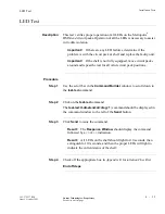
LT-DMXTEND 02-12-12 09:29:50
*C 505 REPT ALM FELAN
"d-1:CR,LOS,SA,12-12,09-29-48:\"inc. FE-LAN LOS\""

