Operational Tests
Automatic Protection Switching and Alarm Test
...........................................................................................................................................................................................................................................................
5 - 1 1
Lucent Technologies - Proprietary
See notice on first page
365-372-327 R2.0
Issue 1, October 2003
............................................................................................................................................................................
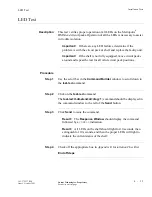
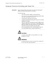
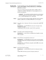
Step 7
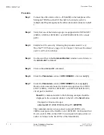
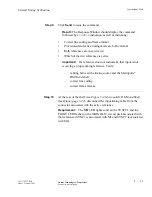
Use the scroll bar in the
Command Builder
window to scroll down to
the
rtrv-crs-sts1
command.
............................................................................................................................................................................
Step 8
Click on the
rtrv-crs-sts1
command.
............................................................................................................................................................................
Step 9
Click
Send
to issue the command.
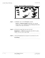
Result:
The Response Window should display the command
followed by a
COMPLD
indication as well as displaying the cross-
connect that was just entered.
............................................................................................................................................................................
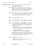
Step 10
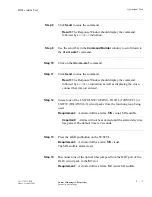
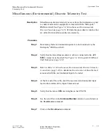
Verify the active path, with the rtrv-state-path command:
............................................................................................................................................................................
Step 11
Click on the
rtrv-state-path
command with
m{1}-1-{1} for a parameter
value
.
............................................................................................................................................................................
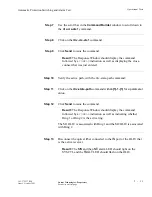
Step 12
Click
Send
to issue the command.
Result:
The Response Window should display the command
followed by a
COMPLD
indication as well as indicating whether
Ring 1 or Ring 2 is the active ring.
The M1 OLIU is associated with Ring 1 and the M2 OLIU is associated
with Ring 2.
............................................................................................................................................................................
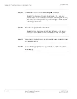
Step 13
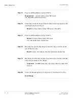
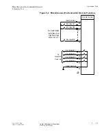
Disconnect the optical fiber connected to the
IN
port of the OLIU that
is the active receiver.
Result:
The
MN
and then
NE
alarm LED should light on the
SYSCTL and the
FAULT
LED should flash on the OLIU.


