Equipment and Cable Installation for Metropolis
®
DMXtend
Shelf Horizontal Bay Mount
DS3/EC-1Cable Installation
...........................................................................................................................................................................................................................................................
1 - 2 5
Lucent Technologies - Proprietary
See notice on first page
365-372-327 R2.0
Issue 1, October 2003
............................................................................................................................................................................................................................................................
DS3/EC-1Cable Installation
Description
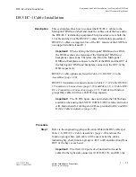
This section describes how to connect the DS3/EC-1 cables to the
Metropolis
®
DMXtend shelf and route the cables out of the bay and to
the DS3/EC-1 terminating equipment.This procedure covers both the
12 cable and the 24 cable DS3/EC1 cables. Perform this procedure if
DS3/EC-1 cables are required. Use of the EC1 feature of the LNW16 is
not supported until release R1.1.
Important!
When cabling the Metropolis
®
DMXtend to a DSX,
the DSX becomes an extension of the Metropolis
®
DMXtend
backplane connections. Therefore, the IN on the Metropolis
®
DMXtend backplane connects to the IN of the DSX and the OUT of
the Metropolis
®
DMXtend backplane connects to the OUT of the
DSX respectively
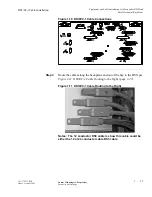
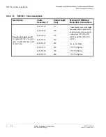
DS3/EC-1 cable options are listed in Table 1-6, DS3/EC-1 Cable
Assemblies (page 1-30).
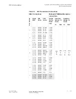
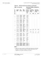
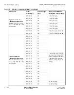
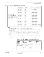
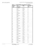
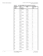
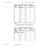
DS3/EC1 transmission connections are in Table 1-7, 24 Cable DS3/EC-
1 Transmission Connections (page 1-33) and Table 1-8, 12 Cable DS3/
EC-1 Transmission Connections (page 1-37). Total of two function
groups fully cabled will have 96 DS3 drop capacity.
Important!
The 96 DS3 figure does not include the 3 DS3 drops
available when using the LNW39 16/DS1/3/DS3 combo card in slot
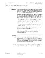
A/B. Instructions for cabling slot A/B are provided in DS1 and DS3
Hybrid Cable Installation (page 1-39).
............................................................................................................................................................................
Procedure
Step 1
Refer to the engineering job specification. Obtain the DS3 cables per
Table 1-6, DS3/EC-1 Cable Assemblies (page 1-30) and note the
function group where each cable will be used. Label the cables,
indicating bay, shelf, function group (A, B, C or D) and direction (IN or
OUT of the bay) at each end.
Important!
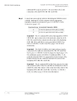
The first 12/24 ports of a Function Unit must be
cabled to the right side connectors (J1D, J3D, J7G, and J9G), the


