Equipment and Cable Installation for Metropolis
®
DMXtend
Shelf Horizontal Bay Mount
DS1 and DS3 Hybrid Cable Installation
...........................................................................................................................................................................................................................................................
1 - 4 1
Lucent Technologies - Proprietary
See notice on first page
365-372-327 R2.0
Issue 1, October 2003
............................................................................................................................................................................
Step 4
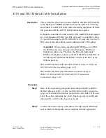
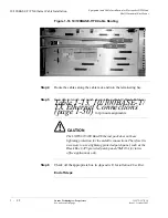
Route the DS1 cables along the cable rack and into the terminating bay
(DSX-1 or other terminating transmission equipment), and route the
DS3 cables along the cable rack and into the terminating bay (DSX-3
or other terminating transmission equipment)
............................................................................................................................................................................
Step 5
Cut the coaxial cables to desired length and install the BNC connectors
shipped with the cable assemblies.
Important!
When installing BNC connectors, follow the
manufacturer’s instruction carefully to ensure a proper connection.
Failure to do so may result in faulty DS3 signals as a result of
improperly installed BNC connectors.
............................................................................................................................................................................
Step 6
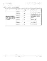
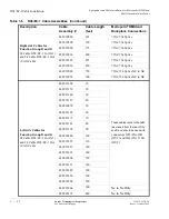
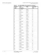
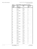
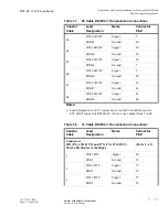
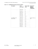
Referring to Table 1-10, DS1 and DS3 Hybrid Cable DS3 Transmission
Connections (page 1-43) connect the cables to their respective
positions on the terminating equipment or DSX.
............................................................................................................................................................................
Step 7
Remove slack and cut the DS1 cables to the desired length at the DSX.
............................................................................................................................................................................
Step 8
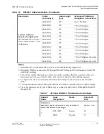
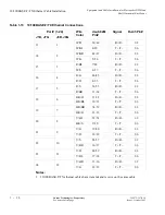
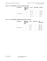
Referring to Table 1-11, DS1 and DS3 Hybrid Cable DS1 Transmission
Connections (page 1-45), carefully observe color codes and wire-wrap
the cables at the DSX.
............................................................................................................................................................................
Step 9
Check off the appropriate box in Appendix E, Installation Checklist.

