background image

255-700-166


7-51

PacketStar

®

 PSAX 6-Port DS1 IMA Module User Guide

,  Issue 1

Release 7.0

Chapter 7  Provisioning Connections Using the Console Interface

Provisioning PVC Connections

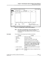
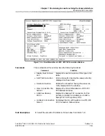
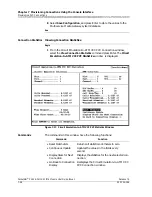
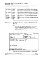
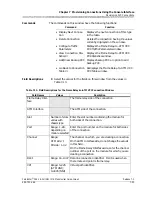
The Frame Relay-to-ATM VCC PVC Table window (see Figure 7-19) is 
displayed.

Note:

At the time of initial installation, the Frame Relay-to-ATM VCC 
PVC Table window is empty. After you have set up connections, 
this window displays all the connections of this type in the 
system.

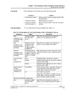
Commands

The commands on this window have the following functions:

Field Descriptions

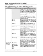
The display-only fields on this window provide the following information 
about all the frame relay-to-ATM PVC connections in the PSAX system:

Figure 7-19.  Frame Relay-to-ATM VCC PVC Table Window

Command

Function

• Find . . .

To find a particular connection, enter val-
ues in the 

Slot, Port, Chnl, VPI

, and 

DLCI/VCI

  fields.  If the connection exists, 

it is displayed on the first line of the table.

• Add a Connection

Displays the Frame Relay-to-ATM VCC 
PVC window.

• Go Back to Connection 

Menu

Redisplays the Connection Configuration 
Menu window.

Summary of Contents for PacketStar PSAX 1250

Page 1: ...Doc No 255 700 166 PacketStar PSAX 6 Port DS1 IMA Module User Guide for PacketStar PSAX Multiservice Media Gateways Issue 1 August 2001 System Software Release 7 0 AQueView EMS Software Release 5 0 ...

Page 2: ...Copyright 2001 by Lucent Technologies All rights reserved For trademark regulatory compliance and related legal information see the Copyright and Legal Notices section ...

Page 3: ...demarks 7R E APX 8000 CellPipe ConnectReach ConnectStar and STINGER are trademarks and PacketStar AQueView Lucent Technologies and the Lucent Technologies logo are registered trademarks of Lucent Technologies in the USA Other product and brand names mentioned in this guide are trademarks or registered trademarks of their respective owners Warranty Information Software and Hardware Limited Warranti...

Page 4: ...ialize and display the accurate configuration of the module that is inserted CAUTION Shipping the chassis with removable modules installed may cause damage to the chassis and the modules Damage to any of the components in the system resulting from shipping the chassis with removable modules installed could void your warranty Only Lucent authorized personnel should ship the Multiservice Media Gatew...

Page 5: ... 1SN This equipment has loop start interface capabilities using an RJ 11C connector The facility interface code with which this equipment complies for service is 02LS2 The service order codes for this equipment are 6 0F for the T 1 interface and 9 0Y for the loop start interface 2 An FCC compliant telephone network interface jack is built into this equipment and is compatible with interconnections...

Page 6: ...connected to the facilities of the local telecommunications company The equipment must also be installed by using an acceptable method of connection In some cases the company s inside wiring associated with a single line individual service may be extended by means of a certified connector assembly telephone extension cord The customer should be aware that compliance with the above condition may no...

Page 7: ...ar le fournisseur Toute réparation ou altération effectuée par l utilisateur ou tout mauvais fonctionnement de cet équipement peut donner à la compagnie de téléphone des raisons de demander audit utilisateur de déconnecter celui ci Pour leur propre sécurité les utilisateurs doivent veiller à ce que les mises à la terre de l alimentation secteur des lignes téléphoniques et du système intérieur de c...

Page 8: ...Copyright and Legal Notices Regulatory Statements viii 255 700 166 PacketStar PSAX 6 Port DS1 IMA Module User Guide Issue 1 Release 7 0 The marking for the 6 Port DS1 IMA module is as follows T D00 0807 ...

Page 9: ... procedures DANGER Read all installation instructions before connecting the system to a power source WARNING Be sure to use the ejector handles during installation and removal of I O and server modules WARNING Electrostatic discharge ESD can damage module and chassis components All personnel should be grounded and follow proper ESD procedures before installing removing or handling hardware compone...

Page 10: ...Safety Warnings and Information x 255 700 166 PacketStar PSAX 6 Port DS1 IMA Module User Guide Issue 1 Release 7 0 ...

Page 11: ...vi CS 03 Issue 8 vi SH 03 Version 8 vii Japanese Regulatory Statements vii JATE vii Safety Warnings and Information ix 1 Getting Started 1 1 Purpose of This Guide 1 1 Audience for This Guide 1 1 What You Should Know 1 1 Related Reading 1 1 Lucent Technologies Information Products 1 1 Product Information Library 1 1 Printed Documents 1 2 About Lucent Technologies 1 2 History 1 2 For More Informatio...

Page 12: ... 3 1 Overview of This Chapter 3 1 Before You Begin 3 1 Loopback Configuration Options 3 2 Configuring the Module 3 3 Configuring the 6 Port DS1 IMA Module 3 3 Configuring the IMA Ports 3 3 IMA Port and Channel Configuration 3 8 Port Statistics 3 12 IMA Groups 3 13 Saving Equipment Configuration and Logging Off 3 18 4 Configuring Ports and Channels Using the AQueView System 4 1 Overview of This Cha...

Page 13: ...Performance 5 6 Configuring the ATM IISP Interface 5 7 ATM User Network Interface 3 0 3 1 and 4 0 5 11 Configuring the Interface 5 11 Viewing ATM UNI Interface Statistics 5 16 Configuring ATM UNI ILMI 5 18 Displaying Registered Addresses 5 20 Viewing ILMI Statistics 5 21 ATM Private Network Network Interface PNNI 1 0 5 23 Optimizing SVC Call Performance 5 23 Configuring the ATM PNNI 1 0 Interface ...

Page 14: ...ILMI 6 34 Setting Up the Interface 6 34 Viewing Registered Addresses 6 37 Viewing ILMI Statistics 6 38 ATM Private Network Network Interface PNNI 1 0 6 39 Setting Up the Interface 6 39 Adding NSAP Addresses 6 45 Copying an Interface Configuration 6 47 Viewing Interface Statistics 6 48 Interface Utilization 6 50 Configuring the Integrated Link Management Interface ILMI 6 53 Setting Up the Interface...

Page 15: ...gement ATM PVC Connection 7 60 Creating an In Band to ATM VCC Connection 7 60 Setting PVC Connections for Direct In band Connections 7 65 Adding VBR to ATM VCC PVC Connections 7 67 Creating a VBR to ATM VCC Connection 7 67 Viewing the VBR to ATM Connection Statistics 7 74 Adding Viewing a Backup PVC Connection 7 77 Adding VBR to VBR VCC PVC Connections 7 79 Adding AAL 2 Trunking to a Connection 7 ...

Page 16: ...2 Managing Connections 8 2 Searching for Specific Connection Entries 8 3 Viewing Connection Details 8 5 Displaying and Updating Connection Information 8 5 Display Connection Tabs 8 6 Copying a Connection Configuration 8 6 Filtering Connections in the List 8 9 Filtering the Listing Page by Connection Type 8 9 Filtering the Listing Page by PSAX Locations 8 11 SPVC NSAP Addresses 8 12 AAL2 Trunk Conf...

Page 17: ...ation to ATM VCC PVC Connections 8 69 Creating a Bridge to ATM VCC Connection 8 69 Primary Page 8 73 Statistics Page 8 74 Backup Page 8 77 Utilization Page 8 80 Adding Frame Relay to ATM VCC PVC Connections 8 82 Creating a Frame Relay to ATM Connection 8 82 Primary Page 8 87 Statistics Page 8 88 Backup Page 8 91 Utilization Page 8 93 Adding an In Band Management ATM PVC Connection 8 96 Disabling a...

Page 18: ...eating a VBR or CBR Routing Table Entry 8 145 Deleting a Routing Table Entry 8 148 Provisioning SPVC Connections 8 150 Adding ATM to ATM VCC SPVC Connections 8 150 Creating an ATM to ATM Connection 8 150 Primary Page 8 156 Statistics Page 8 158 Utilization Page 8 160 Adding Circuit Emulation to ATM VCC SPVC Connections 8 162 Creating a Circuit Emulation to ATM Connection 8 162 Primary Page 8 168 S...

Page 19: ...ork Interface Specification Cause Codes Table B 3 Connection Retry Table B 3 DSP Tone Detection Modes Table B 5 DSP2C Module Channel Reduction Table B 5 Industry Compliance Specifications Table B 6 Interface Type by Connection Type Table B 26 Interface Type by I O Module Type Table B 27 Minimum AAL2 Trunk Size Requirements Tables B 31 Example Using Table B 7 Data for 32 Kbps B 32 Fax Relay Using A...

Page 20: ...Contents xx 255 700 166 PacketStar PSAX 6 Port DS1 IMA Module User Guide Issue 1 Release 7 0 ...

Page 21: ...n in this guide is intended for users who will configure ports and channels for the 6 Port DS1 IMA module configure the interface types and provision connections for the PSAX Multiservice Media Gateway system whether using the console or the AQueView element management software system What You Should Know Before you use this document or operate a PacketStar PSAX device you should already understan...

Page 22: ...ogies History Lucent Technologies is the communications systems and technology company formed through the restructuring of AT T We bring with us a tradition of more than 125 years of experience and a dedication to superior customer service Lucent Technologies manufactures sells and services a complete line of customer premises communications units and commercial and multimedia communications and m...

Page 23: ...edia Gateway is ideal for enterprise networks seeking to consolidate branch office voice video and data traffic onto a single ATM network The PSAX AC 60 system is nonredundant Supporting four slots for I O and server modules this system offers high port density in a small footprint for mid to large sized customer premises applications The PSAX AC 60 chassis has a 650 Mbps back plane and supports a...

Page 24: ... Gbps of switching capacity the highest in the PacketStar family and carrier class reliability The PSAX 4500 system offers an unmatched range of service capabilities end to end traffic prioritiza tion any service any channel flexibility and breakthrough voice technology The new high performance backplane design supports 15 interface slots In four segments the unique PSAX 4500 backplane allows each...

Page 25: ...re identified by this format Note Identifies additional information pertinent to the text preceding this note Appearance How it is used SANS SERIF BOLD ALL CAPS Labels on module panels chassis face plates or other hardware Fixed width normal Message text displayed on the user interface window Serif bold Button name GUI interface or command name console interface on the user interface window Litera...

Page 26: ... Covering Be sure the room has an antistatic floor covering conductive mat tiles or carpeting to minimize static charge buildup as you walk across the room Follow these guidelines for installing and maintaining proper floor coverings Using foot grounding straps attached to the heels of your shoes is recommended even if you are walking in rooms with antistatic floor covering These straps provide ad...

Page 27: ... common electrical ground is a complete circuit between a person or an electrical electronic device and the earth Store components in electrostatic discharge protective bags when they are not in use Technical Support If you experience a problem with your Multiservice Media Gateway system refer to the Lucent Technologies InterNetworking Systems Global Warranty which accompanied your shipment for in...

Page 28: ...tion Safety Information at the beginning of this guide Record your site specific specifications such as the IP addresses you will use and the connections and interfaces you will need Decide which user names and passwords you will assign Make sure you have IP connectivity to all PSAX devices to be managed Determine the numbering scheme for the in band connections you will be using ...

Page 29: ...e from the backplane and is divided between the ports within the IMA group specified in the virtual circuit connection The data leaves the front of the module and is transported across individual T1 lines At the destination IMA module the T1 streams are merged back together in correct order and passed on to other modules as directed by virtual circuit connections IMA dynamically handles conditions...

Page 30: ...ers native DS1 ATM services and DS1 IMA services including permanent virtual circuits soft permanent virtual circuits and switched virtual circuits The module supports UNI v3 a IISP PNNI and ILMI This functionality enables service providers to offer both individual unchannelized DS1 ATM services without IMA overhead and multiple DS1 IMA group services using a single module ACTIVE IMA DS1 FAIL 6 1 ...

Page 31: ...ency CRC mf Hardware Specifications Table 2 1 shows the general physical and environmental hardware specifications for the PSAX Multiservice Media Gateway I O and server modules Chassis Speed Power Consumption and Memory Allocation Chassis speed power consumption and memory allocation specifications for the 6 Port DS1 IMA module are described in Table 2 2 Table 2 1 Physical Hardware Specifications...

Page 32: ...er Con sumption 6 Port DS1 IMA IMA DS1 16 64 MB 8 MB 1 MB Total minus 9 MB Low Speed 18 W 1 The I O buffers carry 16 384 cells per megabyte 2 This column relates only to the performance of the module in the PSAX 4500 chassis All modules operate in a low speed mode in all other PSAX chassis The speed relates to the performance of the data being passed through the midplane of the chassis Table 2 3 L...

Page 33: ...wer is initially applied to the system and the system boot is complete the FAIL and ACTIVE LEDs indicate whether the module has no configured ports red or one or more configured ports green 2 Note After power is initially applied to the system and the system boot is complete this loss of signal LED indicates whether the port has a cable connected to it Table 2 3 LED Indicators for the 6 Port DS1 I...

Page 34: ...Chapter 2 Module Description Hardware Features 2 6 255 700 166 PacketStar PSAX 6 Port DS1 IMA Module User Guide Issue 1 Release 7 0 ...

Page 35: ...ide When configuring the 6 Port DS1 IMA module using the PSAX Multiservice Media Gateway console display only fields are displayed with brackets The status line at the bottom of the console window gives instructions for the field currently selected and displays trap messages see the appendix of your chassis user guide for a table of defined trap messages The configuration of the 6 Port DS1 IMA mod...

Page 36: ...ring a pair of 6 Port DS1 IMA module in the primary and standby setup the desired loopback option must be configured by the user on both the primary and standby modules prior to bringing the pair into service This parameter is applied on a port by port basis on both the primary and standby modules If the line loop or local loop configuration is transferred from port A on the primary module to port...

Page 37: ...timode and Single Mode Traffic Shaping and AQueMan modules 1 Port STM 1 Multimode and Single Mode Traffic Shaping and AQueMan modules The following modules support line loop or local loop only if the standby is preconfigured on a port by port basis 1 Port OC 3c 1 1 APS Multimode and Single Mode modules 1 Port STM 1 1 1 MSP Multimode and Single Mode modules 1 Port OC 12c STM 4c 1 1 APS MSP Multimod...

Page 38: ...le User Guide Issue 1 Release 7 0 Begin Configuring the Ports 4 On the Console Interface Main Menu window see Figure 3 2 select the Equipment Configuration option and press Enter The Equipment Configuration window is displayed see Figure 3 3 and Figure 3 4 Figure 3 2 Console Interface Main Menu Window Equipment Configuration Selected ...

Page 39: ...Release 7 0 Chapter 3 Configuring Ports and Channels Using the Console Configuring the Module Figure 3 3 Equipment Configuration Window As Displayed on the PSAX 20 and AC 60 Console Figure 3 4 Equipment Configuration Window As Displayed on the PSAX 1250 and PSAX 2300 Console ...

Page 40: ...lay Updates the values in the fields to show the most current configuration Use this command mostly to display the most current information in the Line Status field Delete All Interfaces Deletes the configured interfaces for all the ports The value 0 displays in the Channels Configured field You must first take all interfaces out of service using the Take All Interfaces Out Of Service command befo...

Page 41: ...ands The commands in the DS1 IMA Port and Channel Configuration window have the following functions Take All Interfaces Out Of Service Takes the in service configured interfaces for all the ports to out of service status The value 0 displays in the Interfaces In Service field for all six ports You must use this command first before using the Delete All Interfaces command Go Back to Equipment Confi...

Page 42: ...n field values you set Reset Display Resets the port configuration fields to the last set of saved values View Port Statistics Displays the IMA Port Statistics window Bring Interface Into Service Brings the out of service configured inter face for the channel to in service status An asterisk is displayed beside all the con figured channels indicating that they are in service You must first configu...

Page 43: ... and the chassis backplane to the origi nating module PayloadLoop The received signal is sent through the framing chip on the module but not the SAR circuitry and then back out to the originating point The data link is regenerated LineLoop The received signal is sent through the receiver and the line driver and then back out to the originating point Transmit Clock Default LocalTiming Local clock s...

Page 44: ...cketStar Access Concentrator User s Guide NoAlarm default No alarm is present RcvFarEndLOF Far end loss of frame FarEndLOF Near end sending loss of frame indication RcvAIS Far end sending alarm indication signal AIS Near end sending alarm indication signal LossOfFrame Near end loss of frame LossOfSignal Near end loss of signal LoopbackState Near end is looped T16AIS E1 TS16 AIS Rcv FarEndLOMF Far ...

Page 45: ... into service or in service interface has been set to out of service with the Take Interface Out of Service command InService The interface has been brought into ser vice with the Bring Interface Into Ser vice command Oper Status display only Unconfigured This channel is not operational because the interface is not configured OutOfService Two types of problems cause this status A loss of signal co...

Page 46: ...he following procedure 1 Select the View Port Statistics command and press Enter The DS1 IMA Port Statistics window see Figure 3 7 is displayed Commands The commands in this window has the following functions Figure 3 7 DS1 IMA Port Statistics Window Command Function Continuous Update Updates the values in the fields every sec ond Reset Statistics Sets all field values to zero Go Back to DS1 IMA P...

Page 47: ... ports 1 3 5 to Group 1 channel 1 and ports 2 4 and 6 to Group 2 channel 2 and so on Perform the steps in the following procedure to set up the DS1 IMA groups Begin Setting Up DS1 IMA Groups 1 To configure a DS1 IMA group select the Go Back to Port Configuration command or press Ctrl B to return to the DS1 IMA Port and Channel Configuration window see Figure 3 6 on page 3 7 Table 3 2 Data Field De...

Page 48: ...ress Enter The DS1 IMA Virtual Channel Configuration window is displayed see Figure 3 8 Commands The commands in the DS1 IMA Virtual Channel Configuration window have the following functions Figure 3 8 DS1 IMA Virtual Channel Configuration Window Command Function Delete All Interfaces Deletes all configured out of service interfaces The value Unconfig displays in the status field for all interface...

Page 49: ... have the following functions Take All Out of Service Takes the in service configured interfaces to out of service status An asterisk denoting in service is removed from the status field indicating out of service sta tus Go Back to Card Con figuration Redisplays the IMA Card Configuration window Figure 3 9 DS1 IMA Group Configuration Window Command Function Command Function Apply IMA Group Con fig...

Page 50: ... DS1 IMA Group Configuration Window Field Name Values Description Minimum Tx Links Range 1 6 Minimum number of transmit links required to be active for the IMA group to be in the Up state Minimum Rx Links Range 1 6 Minimum number of receive links required to be active for the IMA group to be in the Up state Near end Tx Clock Default ctc Transmit clocking mode used by the near end IMA group The Com...

Page 51: ...rored ICP cells to be detected before moving to the IMA HUNT state The smaller the value the faster the E1 IMA will go into an error state Gamma Value Default 1 Range 1 5 Indicates the gamma value used to specify the number of consecutive valid ICP cells to be detected before moving from the IMA PRESYNC state to the IMA SYNC state Ports In The Group Range 1 6 Displays the ports which are configure...

Page 52: ...t time by performing the steps in the following procedure CAUTION If your system or location loses power or your current session ends abnormally while you are in the process of configuring the system and you have not yet saved the values permanently you will lose all unsaved values you have applied on the various windows Begin Saving the PSAX System Values 1 Press Ctrl G while on any window to dis...

Page 53: ...ts and Channels Using the Console Saving Equipment Configuration and Logging Off retention feature and the result of saving the configuration changes you have made 3 Select the Leave Console Interface command and press Enter You are now logged off the PSAX Multiservice Media Gateway system console interface End ...

Page 54: ...Chapter 3 Configuring Ports and Channels Using the Console Saving Equipment Configuration and Logging Off 3 20 255 700 166 PacketStar PSAX 6 Port DS1 IMA Module User Guide Issue 1 Release 7 0 ...

Page 55: ...figuration of the 6 Port DS1 IMA module involves the following major tasks 1 Each port must be configured with the IMA interface and that IMA interface must be brought into service 2 Each IMA group must be established 3 Each IMA group must be configured with an ATM interface IISP UNI or PNNI CAUTION When using a DSP2A DSP2B DSP2C or DSP2D Voice Server module and an Enhanced DS1 or E1 module with a...

Page 56: ...dule to port B on the standby module the port parameter does not transfer it must be pre configured on the standby by the user The following modules support line loop or local loop only if the standby is preconfigured on a port by port basis 1 Port OC 3c 1 1 APS Multimode and Single Mode modules 1 Port STM 1 1 1 MSP Multimode and Single Mode modules 1 Port OC 12c STM 4c 1 1 APS MSP Multimode and S...

Page 57: ... Menu Table 4 1 Descriptions of the Port and Channel Configuration Right Click Menu Options Option Function Configure Opens the port and channel configuration window of a module Bring All Inter faces Into Service Sets all interfaces on a port administratively into service Take All Inter faces Out of Ser vice Takes all interfaces on a port administratively out of ser vice Delete All Inter faces Del...

Page 58: ...he port and channel configuration functions in the AQueView system do the following 1 Log in to the AQueView system as a user with Administrator or Configurator access privileges 2 From the Device List or the Open Device window press Ctrl D or Ctrl O open the PSAX device that contains the module on which you want to configure a port or channel The Front Panel view and Device Tree for that PSAX dev...

Page 59: ...rt DS1 IMA module Begin Configuring the Ports 1 Do one of the following to open the Port and Channel Configuration window In the Front Panel click the left button twice on the port to be configured or displayed see Figure 4 5 In the Front Panel double click the right button on the port and a menu appears Click Configure in the menu that appears In the Device Tree double click the desired port symb...

Page 60: ...select a port then click the right mouse button on the Device Tree and a menu appears Click Configure The DS1 IMA Port and Channel Configuration window appears see Figure 4 6 The DS1 IMA Port and Channel Configuration window contains The Port Configuration page allows you to do the following Figure 4 5 Front Panel View of the DS1 IMA Module Figure 4 6 DS1 IMA Port and Channel Configuration Window ...

Page 61: ...d in Table 4 2 Button Function Close Closes this window Apply Applies the configuration field value you set Reset Resets the fields to the last set of applied values Copy Copies a port configuration to a range of ports Update Updates the information in the fields Clear Removes the values in the Port Statistics panel and resets them to 0 Poll or Poll Poll initiates the continuous update of statisti...

Page 62: ...s used as the timing source LoopTiming Recovered receive clock is used as the transmit clock Line Build Out Default Up To 133 Feet Indicates the DS1 signal is designed to be valid from 0 to 133 feet Up To 266 Feet Indicates the DS1 signal is designed to be valid from 134 to 266 feet Up To 399 Feet Indicates the DS1 signal is designed to be valid from 267 to 399 feet Up To 533 Feet Indicates the DS...

Page 63: ... LossOfSignal Near end loss of signal LoopbackState Near end is looped T16AIS E1 TS16 AIS Rcv FarEndLOMF Far end sending TS16 LOMF FarEndLOMF Near end sending TS16 LOMF RcvTestCode Near end detects a test code OtherFailure Any line status not defined here RmtLoopback Far end loopback Interface Type is displayed on the Channel Configuration page Unconfigured This interface is not configured Ima Thi...

Page 64: ...ort of the module you selected in the Start At and Stop At panels see Figure 4 7 Oper Status display only displayed on the Channel Configuration page Unconfigured This channel is not operational because the interface is not configured OutOfService Two types of problems cause this status A loss of signal condition exists due to any one of the following The module port is not physically connected to...

Page 65: ...ts click the box beside Overwrite configured interfaces this option is only available if Copy interface configuration is selected Note The Overwrite configured interfaces option is ghosted until you click the box beside Copy interface configuration 5 Click Copy The port configuration is copied to the range of ports you selected End Channel Configuration Perform the steps in the following procedure...

Page 66: ...sing the AQueView System 3 Select the values for this interface as described in Chapter 6 4 To update the interface configuration display click Update 5 To activate the interface click Bring Into Service The value InService is displayed in the Administrative Status and Operational Status fields 6 On the Channel Configuration window click Apply to Selected 7 Click the right mouse button in the list...

Page 67: ...IMA channels for each module and each channel can contain up to six ports Up to three channels can be configured on the virtual port port 7 A group must have at least two and up to six of the physical ports assigned to it For example Table 4 3 Data Field Descriptions of the DS1 IMA Port Statistics Window Field Names Description Errored Seconds A second with at least one of the foll wing Path Code ...

Page 68: ...ting the Values for the DS1 IMA Virtual Channels 1 Do one of the following to open the Port and Channel Configuration window In the Front Panel double click the left mouse button on the port to be configured or displayed In the Front Panel double click the right button on the port and a menu appears Click Configure in the menu that appears In the Device Tree double click the desired port symbol or...

Page 69: ...ndow Table 4 4 Field Values for the IMA Virtual Channel Configuration Page Field Name Values Description Interface Type Default Unconfigured The interface for this channel is not configured AtmUni3_0 This interface is configured for ATM UNI 3 0 interface AtmUni3_1 This interface is configured for ATM UNI 3 1 interface IispUser This interface is configured for ATM IISP User interface IispNetwork Th...

Page 70: ...d from the same source You must set up the underlying clock configuration to ensure operation in the selected mode itc The Independent Transmit Clock ITC mode corresponds when there is at least one IMA link whose transmit clock is derived from a source different than at least one other link transmit clock You must set up the underlying clock con figuration to ensure operation in the selected mode ...

Page 71: ...erface Configuration window appears 8 Click the right mouse button in the list in the Channel Configuration window and a menu appears Click Bring Into Service 9 Repeat this procedure to configure additional virtual channels 10 Click Close End Alpha Value cells Default 2 Range 1 2 Indicates the alpha value measured in cells measured in cells used to specify the number of consecutive invalid ICP cel...

Page 72: ... 6 Port DS1 IMA module IMA Channel Details On the IMA Virtual Channel Configuration window click the Channel 1 Details tab or whichever channel number of which you wish to view statistics The Channel 1 Details page appears see Figure 4 10 Buttons The buttons in this window have the following functions Figure 4 10 DS1 IMA Channel Details Window Button Function Update Updates the information in the ...

Page 73: ...ase where there is at least one IMA link whose transmit clock is derived from a source different than at least another link transmit clock Rx IMA ID display only Default 0 Range 0 255 The IMA ID currently in use by the far end IMA function Rx Frame Length display only Default M32 m64 m128 m256 Value of IMA frame length as received from remote IMA function Least Delay Link display only Default Port...

Page 74: ...he Operational state This state is excited whe sufficient links can be moved into the Active state Blocked The group is blocked e g inhibiterd by the UM The group can be blocked for maintenance purposes while sufficient links are Active in both directions The group is not inhibited and has suffi cient links in both the Tx and Rx directions The IMA interface has now the capability to receive ATM la...

Page 75: ... parameters and that the far end has also accepted its own group parameters and does not have sufficient links to move into the Operational state This state is excited whe sufficient links can be moved into the Active state Blocked The group is blocked e g inhibited by the UM The group can be blocked for maintenance purposes while sufficient links are Active in both directions The group is not inh...

Page 76: ...LinksNe InsuffLinksFe BlockedNe BlockedFe OtherFailure Group Symmetry display only Symmetry of the IMA group Default Sym Operation Symmetric operation AsymOperation Asymmetric operation AsymConfigu ration Asymmetric configuration IMA Group Statistics panel display only Near end Fail ures Default 0 Count of near end Rx failure alarm con ditions has been entered on this link Far end Fail ures Defaul...

Page 77: ...Using the Right Click Menu Number of Active Rx Links Default 0 Range 1 32 Minimum number of receive links required to be Active for the IMA group to be in the Up state Time Elapsed Default 0 days 00 00 00 Time elapsed in days hours minutes and seconds since last reset Table 4 5 Field Values for the IMA Channel Details Page Field Name Values Description ...

Page 78: ...Chapter 4 Configuring Ports and Channels Using the AQueView System Using the Right Click Menu 4 24 255 700 166 PacketStar PSAX 6 Port DS1 IMA Module User Guide Issue 1 Release 7 0 ...

Page 79: ...ace types see the Interface Types by I O Module Types Table in the Reference Tables appendix of your PacketStar PSAX User Guide Errors in Applying Interfaces to Ports An error can occur when you apply an interface to a port or channel If an error condition occurs the Multiservice Media Gateway sends an SNMP trap that usually appears in the console Trap Log Display accessible from the Console Inter...

Page 80: ...states to the far end of an IMA connection you must configure IMA groups with the compatibility mode turned on This also causes the PSAX unit to correctly report link states and interoperate with your ATM Forum IMA ATM Specification Version 1 0 equipment The following is a list of operations considerations for the IMA interface Once an IMA group has been deleted its status is displayed as Insuffic...

Page 81: ...is configured and the far end is connected to equipment that doesn t support it the far end group enters the config abort state The IMA identifier ID is an 8 bit 0 255 identifier for this IMA group There is no significance to any particular values of IMA IDs Since the IMA ID is used to identify a group to the far end pick a unique value instead of leaving it as the default of 0 Accessing the ATM I...

Page 82: ...layed asterisk is removed from all configured channels indicating that they are out of service Note You must use this command first before using the Delete Interface and Return command Delete Interface and Return Deletes an out of service interface and redisplays the ATM IMA Configuration window Note You must first take interface out of service using the Take Interface Out of Service command befor...

Page 83: ... far end If cables are then removed and plugged back in differently then the equipment may signify that it is misconnected Unusable Inhib ited This is an administrative mechanism for tak ing an IMA link out of service When in this state it is unknown whether there are any physical problems with the link Unusable Failed Check the defect value displayed Usable There are no local reasons why this lin...

Page 84: ...ce is configurable as either the user side or the network side Optimizing SVC Call Performance The service specific connection oriented protocol SSCOP field is set on these interface configuration windows ATM IISP network or IISP user ATM UNI 3 0 or UNI 3 1 or ATM PNNI 1 0 Note These settings are suggested for connecting to a Multiservice Media Gateway from a remote site only The Multiservice Medi...

Page 85: ...to 32 for all ATM interfaces on the Multiservice Media Gateway The interfaces of the ATM switches that are connected to an Multiservice Media Gateway should be configured to the same values This results in 100 call completion at a call setup rate of 60 calls per second using even distribution If these values are not configured in this way calls will be set up at a rate of less than 60 calls per se...

Page 86: ...lue InService is displayed in the Admin Status field You must first configure the interface before you can use this command Take Interface Out of Service displays when the Admin Status field is InService Takes an in service configured interface to out of service status The value OutOfService is displayed in the Admin Status field Note You must use this command first before using the Delete Interfa...

Page 87: ...n service OutOfService The interface is not in service Over Subscription Default 10 Range 1 100 The risk factor for this function This factor indicates the fac tor of oversubscription allowed for this interface Note For the maximum and minimum VPI VCI values below always enter or change the maximum value before the minimum value Min SVC VPI Default 0 Range 0 255 The minimum VPI value in which sign...

Page 88: ... SSCOP Rx Wnd Size The service specific connection oriented protocol SSCOP layer This window shows the total number of packets that must be acknowledged by the receiving side before more packets are sent from the transmitting side Default 32 Range 8 256 On the receiving side values must be equal to or greater than the values for the transmit side for fastest transmission rates Traffic Shaping An i...

Page 89: ... the statistics were last reset Valid Cells Sent Number of valid cells sent since the statistics were last reset Null Cells Sent Number of null cells sent since the statistics were last reset Time Elapsed Time elasped since counter began running since the statistics were last reset Ingress Avail BW cps display only Default 0 This represents the total ingress and egress bandwidth avail able for vir...

Page 90: ...ce configured interface to in service status The value InService is displayed in the Admin Sta tus field Note You must first configure the interface before you can use this command Take Interface Out of Service displays when the Admin Status field is InService Takes an in service configured interface to out of service status The value OutOfService is displayed in the Admin Status field Note You mu...

Page 91: ...criptions for the ATM UNI Interface Configuration Window Field Name Values Description Over Subscription Default 10 Range 1 100 The risk factor for this function This factor indicates the level of oversubscription allowed by the system Note For the maximum and minimum VPI and VCI values below always enter or change the maximum value before the minimum value Min Max SVC VPI The minimum and maximum ...

Page 92: ...ype field This address is used only for address registration proce dure of ILMI This field represents the first 13 bytes of the 20 byte NSAP address The last 7 bytes are the user part of this address User Add field User Add Default 2020202020202 0202020202020 Range 13 byte 18 hexadeci mal digit begin ning with 39 45 or 47 User address displays when the value User is selected in the Interface Type ...

Page 93: ...onnection oriented protocol SSCOP layer This window shows the total number of packets that must be acknowledged by the receiv ing side before more packets are sent from the trans mitting side Default 32 Range 8 256 On the receiving side the window size for this value must be equal to or greater than the values for the transmitting side for fastest transmission rates VI Support Virtual interfaces c...

Page 94: ...bandwidth available for virtual interfaces The value 0 changes to 353207 after you select the Apply command As each new virtual interface is created the amount of available bandwidth as indicated in this field decreases Egress Avail BW cps display only Default 0 This represents the total egress bandwidth available for virtual interfaces The value 0 changes to 353207 after you select the Apply comm...

Page 95: ...Command Function Continuous Update Continuously updates all fields once every second Reset Statistics Resets statistics counters for this interface Go Back to previous screen Returns to the ATM UNI Interface Configuration window Table 5 4 Field Values for the ATM UNI Interface StatisticsWindow Field Name Description Valid Cells Rcvd Number of valid cells received into interface side A dur ing the ...

Page 96: ...mands in this window have the following functions Mismatched Cells Rcvd Number of mismatched cells received into interface side A during the amount of time shown in Time Elapsed field Valid Cells Sent Number of valid cells transmitted out of interface side B during the amount of time shown in Time Elapsed field Null Cells Sent Number of null cells transmitted out of interface side B during the amo...

Page 97: ...perational OutOfService Indicates that ILMI connectivity is not operational ILMI Protocol Default Disabled If you select Disabled the other fields in this window will not take effect Enabled Enables ILMI Address Registration Default Disabled Address registration can be enabled only if the ILMI Protocol field is enabled Enabled Enables address registration Connectivity Procedure Default Disabled IL...

Page 98: ... Auto Configu ration display only Default Disabled The ability to automatically configure VPI and VCI is disabled Enabled Automatically configures the VPI and VCI Auto configuration can be enabled only if the ILMI Protocol field is enabled TimerT display only Default 5 Range Varies Timer T in seconds Used to poll when link is opera tional The value in this field in displayed as a 32 bit integer an...

Page 99: ...ys the scope of the registered addresses If the scope is not set by the user it will default to global a value of 15 6 To go back to the ATM UNI Interface Configuration window select the Go Back to Interface Screen command and press Enter Viewing ILMI Statistics To view ILMI configuration statistics do the following 7 Select the ILMI Statistics command and press Enter The ILMI Statistics window is...

Page 100: ...tinuous Update Continuously updates the information in the fields every second Select this command and press Enter to turn the continuous updating on and off as needed Reset Statistics Resets the statistics counters for the ILMI Statis tics window Go Back to Interface Screen Redisplays the ATM UNI Interface Configuration window Table 5 6 Field Descriptions for the ILMI Statistics Window Field Name...

Page 101: ...timize call performance the SSCOP Rx Window Size field of the local ATM interface should be less than the maximum value displayed in the MaxPD credit window at the remote end of the ATM interface Otherwise the rate at which switched calls can be set and released may be degraded AttachPt Verified display only Number of times attachment point was verified successfully Secure Link Proc Initiated disp...

Page 102: ...ond using even distribution If these values are not configured in this way calls will be set up at a rate of less than 60 calls per second Note Various SSCOP parameter settings determine the maximum credit window As a result you may not be able to directly use these settings Configuring the ATM PNNI 1 0 Interface To set the values for the ATM PNNI interface perform the steps in the following proce...

Page 103: ... Ser vice displays when the Admin Status field is OutOfService Brings an out of service configured interface to in ser vice status The value InService is displayed in the Admin Status field You must first configure the interface before you can use this command Take Interface Out of Ser vice displays when the Admin Status field is InService Takes an in service configured interface to out of ser vic...

Page 104: ...nterface Configuration Window Field Name Values Description Node Index Range 0 65535 An index that identifies a logical PNNI entity within the managed system The value zero indi cates a logical entity within the switching system that manages routes only over non PNNI inter faces By default only the node identified by the node index is created and all PNNI interfaces are associated with that node o...

Page 105: ... Enables UPC support providing traffic policing support for all VCs Traffic Shaping An input cell selection algorithm leaky bucket that smooths bursts of input traffic Available only on these modules OC 3c Multi mode and Single Mode STM 1 Multimode and Single Mode Default Disabled Feature disabled Enabled Feature enabled Note Setting must be enabled if using rate shaping on the OC 3c APS or the ST...

Page 106: ...Min Max SVC VCI display only Default 32 65535 The lower upper boundary of the VCI for SVC connections for the remote side Port Id display only Default 201001 The interface port identifier identifies a point of attachment of a logical link to a given logical node This is automatically generated based on the location slot port channel of the interface A value of 0 indicates that no port has been spe...

Page 107: ...operational OutOfService Indicates that the interface is not operational Ingress Avail BW display only Default 0 Available bandwidth for the incoming direction Egress Avail BW display only Default 0 Available bandwidth for the outgoing direction AdminWeight cbr Default 5040 Range 504 16777215 The administrative weight for the constant bit rate service category Used by PNNI in path selec tion The h...

Page 108: ...y Interface Configuration command and press Enter 6 To activate the interface after you have applied the configuration values select the Bring Interface Into Service command and press Enter End Configuring PNNI ILMI Perform these steps to configure your connection for PNNI integrated link management interface ILMI Begin Steps to Configure the PNNI ILMI Interface 1 From the ATM PNNI Interface Confi...

Page 109: ...sabled Address registration can be enabled only if the ILMI Pro tocol field is enabled Enabled Enables address registration Connectivity Procedure This field detects the establishment and subsequent loss of ILMI connectivity Default Disabled ILMI Connectivity Procedure is disabled You must select Enabled if you want to also enable the Attachment Point Detection and Secure Link fields Enabled ILMI ...

Page 110: ...on 8 3 4 Enabled If enabled the actual VPI VCI are automatically config ured and the connections are set up by using the overlap VPI VCI ranges of the local VPI VCI and the remote VPI VCI ranges Auto configuration can be enabled only if the ILMI Proto col field is enabled TimerT Default 5 Range 0 232 1 Timer T in seconds Used to poll when link is operational The value in this field in displayed as...

Page 111: ...the following procedure to view PNNI ILMI statistics Begin Procedure for Viewing PNNI ILMI Interface Statistics 1 To view interface statistics for this connection select the ILMI Statistics command on the ATM PNNI Interface Configuration window and press Enter or press Ctrl I The PNNI ILMI Interface Statistics window is displayed see Figure 5 11 The commands on this window have the following funct...

Page 112: ...unters for this interface Go Back to previous screen Returns to the ATM PNNI InterfaceConfigura tion window Table 5 9 Field Values for the ATM PNNI ILMI Interface Statistics Window Field Name Description Valid Cells Rcvd Number of Valid cells received into interface side A during the amount of time shown in Time Elapsed field Errored Cells Rcvd Number of Errored cells received into interface side ...

Page 113: ...s on this window have the following functions Field Descriptions 3 Select the values for the fields on this window from Table 5 10 Figure 5 11 ATM PNNI Interface Statistics Window Command Function Continuous Update Continuously updates all fields once every second Reset Statistics Resets statistics counters for this interface Go Back to previous screen Returns to the ATM PNNI Interface Configurati...

Page 114: ... at any time after the interface has been brought into service you must first take the interface out of service delete the interface and then re create the interface by configuring the desired values Table 5 10 Field Values for the ATM PNNI Interface Statistics Window Field Name Description Valid Cells Rcvd Number of valid cells received into interface side A during the amount of time shown in Tim...

Page 115: ...le in the Reference Tables appendix of your PacketStar PSAX User Guide Errors in Applying Interfaces to Ports An error can occur when you apply an interface to a port or channel See the appendix SNMP Trap Messages for more information about the SNMP traps related to interface errors Entering values into fields that are outside of the configurable range of values Attempting to configure an interfac...

Page 116: ...aking it administratively out of service and then bringing it back into service In order to change any group configuration parameters the group must be completely unconfigured There may be difficulties if the IMA group is configured for symetric operation but has asymetric link delays For example one end may consider links A B and C to have problems while the other end considers D E and F to have ...

Page 117: ...e the interface before you can use this button Take Out of Service displays when the Administrative Status field is InService Takes an in service configured interface to out of service status The value OutOfService is dis played in the Administrative Status field Note You must use this command first before using the Delete button Delete Deletes an out of service interface and redis plays the Port ...

Page 118: ...oll suspends polling Button Function Table 6 1 Field Values for the ATM IMA Interface Configuration Window Field Name Values Description Interface Type display only Ima The interface type you are configuring Cell Scramble Disabled default Disables ATM cell payload scrambling Enabled Enables ATM cell payload scrambling opti mized cell synchronization IMA Configuration panel display only Operational...

Page 119: ...he far end If cables are then removed and plugged back in differently then the equipment may signify that it is misconnected Unusable Inhib ited This is an administrative mechanism for tak ing an IMA link out of service When in this state it is unknown whether there are any physical problems with the link Unusable Failed Check the defect value displayed Usable There are no local reasons why this l...

Page 120: ...ltiple Channels 1 In the Interface Configuration window click Copy The Copy Interface Configuration window appears with the slot port and channel of the interface you selected in the Start At and Stop At panels see figure below Near end Rx Failures Count of near end Rx failure alarm conditions has been entered on this link Far end Tx Failures Count of far end transmit failure alarm condi tions has...

Page 121: ...lick the box beside Overwrite configured interfaces 4 Click Copy The interface configuration is copied to the range of channels you selected 5 Click Close End Interim Interswitch Signaling Protocol IISP Interface This section provides instructions for configuring an I O module for the Interim Interswitch Signaling protocol IISP user and network interfaces IISP formerly known as PNNI Phase 0 was in...

Page 122: ...nterface requires the default range of values 0 255 for the virtual path identifier VPI and the virtual channel identifier VCI to accept and establish calls Each connection using the IISP interface is configurable as either the user side or the network side Setting Up the Interface When you select IispUser or IispNetwork as the interface type in the Channel Configuration page the IISP Interface Co...

Page 123: ...channel selected in the fields on the bottom right panel Bring Into Service dis plays when the Admin istrative Status field is OutOfService Brings an out of service configured interface to in service status The value InService is dis played in the Administrative Status field Note You must first configure the interface before you can use this button Take Out of Service displays when the Administrat...

Page 124: ...ndicates the Administrative Status of the interfaces or what the interface s are configured as InService The interface is in service OutOfService The interface is not in service Over Subscription Default 10 Range 1 100 The risk factor for this function This factor indicates the fac tor of oversubscription allowed for this interface Note For the maximum and minimum VPI VCI values below always enter...

Page 125: ...l BW cps display only Default 0 This represents the total ingress and egress bandwidth avail able for virtual interfaces As each new virtual interface is created the amount of available bandwidth as indicated in this field will decrease The value of this field ranges from 0 353207 after being brought in service Egress Avail BW cps display only Default 0 This represents the total ingress and egress...

Page 126: ...er a valid NSAP address in the Local NSAP Address Hex field and click Retrieve from NSAP database If the value entered in the Local NSAP Address Hex field is valid the field becomes ghosted The Select NSAP window appears see the following figure Traffic Shaping An input cell selection algorithm leaky bucket that smooths bursts of input traffic Available on these modules only STM 1 Multi Mode and S...

Page 127: ... the Remote Switch IP field The list of NSAP addresses previously configured for that PSAX device is displayed in the table 4 Select the desired entry slot port channel and NSAP address and click Retrieve The Local NSAP Address Hex field becomes populated in the window Note If the desired remote device does not appear in the Remote Switch IP pull down menu do the following Figure 6 4 Select NSAP W...

Page 128: ... AQueView system save these database changes to the text editor file by using the main AQueView Menu Bar Click View NSAP Database Save 5 To apply the interface configuration values click Apply 6 To activate the interface after you have applied the configuration values click Bring Into Service Note The interface must have in service status so that the PVCs and SVCs you will set up to use this inter...

Page 129: ...in the Slot Port and Channel fields 3 To overwrite the pre existing interface configuration click the box beside Overwrite configured interfaces 4 Click Copy The interface configuration is copied to the range of channels you selected 5 Click Close End Viewing Interface Statistics To view interface statistics click the Interface Statistics tab The Interface Statistics page appears see Figure 6 6 Fi...

Page 130: ...have the following functions Field Descriptions Descriptions of the ATM IISP Interface Statistics window are described in Table 6 3 Figure 6 6 ATM IISP Interface Statistics Page Button Function Update Updates the information in the fields Clear Removes the values in this window and resets them to 0 Poll Poll initiates the continuous update of statistics and changes the button to Poll Poll suspends...

Page 131: ...ure 6 7 Table 6 3 Field Values for the ATM IISP Interface Statistics Page Field Name Description Valid Cells Received Number of valid cells received into interface side A during the amount of time shown in Time Elapsed field Errored Cells Received Number of errored cells received into interface side A during the amount of time shown in Time Elapsed field Mismatched Cells Received Number of mismatc...

Page 132: ...A Module User Guide Issue 1 Release 7 0 Utilization Page Buttons The buttons at the bottom of the window have the following functions Figure 6 7 ATM IISP Utilization Page Button Function 60 sec Time in seconds or minutes to poll the PSAX device Select a time interval from the pull down menu 5 sec 10 sec 20 sec 30 sec 60 sec default 90 sec 2 min 3 min 4 min 5 min ...

Page 133: ...arked increases decreases in any one of these calculations The Average Bits Sec panel displays the percentage of traffic that is passing through the channel The Average Throughput panel displays the percentage of the channel that is being used from the total amount of bandwidth for the channel shown in the Total Bandwidth bps panel The Total Bandwidth bps panel displays the total width of the chan...

Page 134: ...his section provides instructions for configuring an I O module for the ATM user to network interface UNI 3 0 3 1 4 0 and Integrated Link Management Interface ILMI interfaces Setting Up the Interface When you select AtmUni3 0 AtmUni3 1 or AtmUni4 0 as the interface type in the Channel Configuration page the ATM UNI Interface Configuration window appears see Figure 6 8 and Figure 6 9 Figure 6 8 ATM...

Page 135: ... previously established an NSAP address database click this button to retrieve an entry from this list to populate the Local NSAP Address Hex field Calculate Navis NSAP Address Note This button appears only when you con figure user properties to include the Navis NSAP format For more information see the appropriate AQueView Element Management Sys tem User Guide Automatically calculates the local N...

Page 136: ...t use this command first before using the Delete button Delete Deletes an out of service interface and redis plays the Port and Channel Configuration win dow for the module you are configuring You must first take interface out of service by clicking the Take Out of Service button before you can use this button Copy Copies this interface to a range of slots ports and channels Close Closes this wind...

Page 137: ... for use Interface Type Default Network Indicates that the NNI format for the cell headers will be used Note When you select this value the Network Prefix field is displayed below the Interface Name field User Indicates that the UNI format for the cell headers will be used Note When you select this value the User Address field is displayed below the Interface Name field Interface Name Maximum stri...

Page 138: ...Name Format 20 alphanumeric characters This field is used for identifying network topology Enter a descriptive name up to 20 characters in length for the PSAX chassis or other device to which the physical connection is made using this interface UPC Support Usage parameter control policing determines if traffic control is performing to negotiated PCR SCR or MBS This feature is supported on these mo...

Page 139: ...ing side before more packets are sent from the trans mitting side Default 32 Range 8 256 On the receiving side the window size for this value must be equal to or greater than the values for the transmitting side for fastest transmission rates VI Support Virtual interfaces connect to a module s physical ports and allow virtual channels VCs to be assigned to virtual trunks each with its own priority...

Page 140: ... NSAP address in the Local NSAP Address Hex field and click Retrieve from NSAP database If the value entered in the Local NSAP Address Hex field is valid the field becomes ghosted The Select NSAP window appears see the following figure Traffic Shaping An input cell selection algorithm leaky bucket that smooths bursts of input traffic Available on these modules STM 1 Multimode and Single Mode OC 3c...

Page 141: ... Remote Switch IP field The list of NSAP addresses previously configured for that PSAX device is displayed in the table 5 Select the desired entry slot port channel and NSAP address and click Retrieve The Local NSAP Address Hex field becomes populated in the window Note If the desired remote device does not appear in the Remote Switch IP pull down menu do the following Figure 6 10 Select NSAP Wind...

Page 142: ...text editor file by using the main AQueView Menu Bar Click View NSAP Database Save 6 To apply the interface configuration values click Apply 7 If you want to use the ILMI protocol you must select Enabled in the ATM Signaling field ILMI is not required if ATM signaling is disabled 8 For more information about using the NSAP database see the section Using the NSAP Address Database in Chapter 8 of th...

Page 143: ...erwrite the pre existing interface configuration click the box beside Overwrite configured interfaces 4 Click Copy The interface configuration is copied to the range of channels you selected 5 Click Close End Viewing ATM UNI Interface Statistics To view statistics for the ATM UNI interface on the ATM UNI Interface Configuration window click the Interface Statistics tab The ATM UNI Interface Statis...

Page 144: ...ase 7 0 Buttons The buttons on this window have the following functions Field Descriptions The fields on this window are described in Table 6 5 Figure 6 12 ATM UNI Interface Statistics Page Button Function Update Updates the information in the fields Clear Removes the values in this window and resets them to 0 Poll Poll initiates the continuous update of statistics Poll suspends polling ...

Page 145: ...cs Page Field Name Description Valid Cells Received Number of valid cells received into interface side A dur ing the amount of time shown in Time Elapsed field Errored Cells Received Number of errored cells received into interface side A during the amount of time shown in Time Elapsed field Mismatched Cells Received Number of mismatched cells received into interface side A during the amount of tim...

Page 146: ... ATM User Network Interface UNI 3 0 3 1 and 4 0 6 32 255 700 166 PacketStar PSAX 6 Port DS1 IMA Module User Guide Issue 1 Release 7 0 Utilization Page Buttons The buttons at the bottom of the window have the following functions Figure 6 13 ATM UNI Utilization Page ...

Page 147: ...t intervals ranges from 5 seconds 5 minutes default interval is 60 seconds A maximum of 10 measurements are displayed which enables you to quickly discern marked increases decreases in any one of these calculations The Average Bits Sec panel displays the percentage of traffic that is passing through the channel The Average Throughput panel displays the percentage of the channel that is being used ...

Page 148: ...ormation base MIB that provides status and communication information to the PSAX system and other switching devices configured for ATM UNI ILMI supports bidirectional exchange of ATM interface parameters between two connected ATM Interface Management Entities IMEs ILMI provides status information and statistics using Simple Network Management Protocol SNMP and a MIB to provide any ATM device with ...

Page 149: ...ions Figure 6 14 ILMI Configuration Page Button Function Registered User Address Table Displays the Registered User Address Table Apply Applies the configuration field values you set Reset Resets the fields to the last set of applied values Close Closes this window Update Updates the information in the fields Clear Removes the values in this window and resets them to 0 Poll or Poll Poll initiates ...

Page 150: ...Detection and Secure Link fields Enabled ILMI Connectivity Procedure is enabled Attachment Point Detection Default Disabled Enabled Attachment Point Change Detection can be enabled only if Connectivity Procedure and ILMI Protocol fields are enabled Enabled A query will be sent every 5 seconds to detect a change in the address A response indicates that the user id and address information are the sa...

Page 151: ...red User Address Table on the ILMI Configuration page The ILMI Registered User Address Table window appears see Figure 6 15 Timer S Default 1 Range Varies Timer S in seconds Used to poll when link is not operational The value in this field in displayed as a 32 bit integer and any number may appear Retry K Default 4 Range Varies Retry K in seconds Indicates the number of timeouts before the link be...

Page 152: ...uration page see Figure 6 14 Field Descriptions Descriptions of the ILMI statistics data fields are given in Table 6 7 Figure 6 15 Registered User Address Table Table 6 7 Field Descriptions for the ILMI Statistics Page Field Name Description Link Resets display only Number of times connectivity went down and then up again Attachment Point Changed display only Number of times attachment point chang...

Page 153: ...ust first configure the PNNI node see Chapter 6 in the appropriate AQueView Element Management System User Guide When you select AtmPnni1_0 as the interface type in the Channel Configuration page the ATM PNNI Interface Configuration window appears see Figure 6 16 Cold Starts Transmitted display only Number of times a Cold Start trap message was transmitted Cold Starts Received display only Number ...

Page 154: ...ystem ATM Private Network Network Interface PNNI 1 0 6 40 255 700 166 PacketStar PSAX 6 Port DS1 IMA Module User Guide Issue 1 Release 7 0 Buttons The buttons in this window have the following functions Figure 6 16 ATM PNNI 1 0 Interface Configuration Window ...

Page 155: ...l selected in the fields on the bottom right panel Bring Into Service dis plays when the Admin istrative Status field is OutOfService Brings an out of service configured interface to in service status The value InService is dis played in the Administrative Status field Note You must first configure the interface before you can use this button Take Out of Service displays when the Administrative St...

Page 156: ...ange 1 255 for low speed modules 1 4095 for high speed modules See Note at right The lower boundary of the VPI for SVC connec tions Note As the PNNI signaling field is enabled by default on this interface VPI 0 is not available Maximum SVC VPI Default 0 Range 1 255 for low speed modules 1 4095 for high speed modules See Note at right The upper boundary of the VPI for SVC connec tions Note As the P...

Page 157: ...aces do not support UBR load balancing Default Disabled UBR load balancing is disabled Enabled UBR load balancing is enabled AdminWeight CBR Default 5040 Range 504 16777215 The administrative weight for the constant bit rate service category Used by PNNI in path selec tion The higher the weight the lower the prior ity See the note below this table AdminWeight RT VBR Default 5040 Range 504 16777215...

Page 158: ...play only The lower upper boundary of the VPI for SVC connections for the remote side Port Id display only Default 201001 The interface port identifier identifies a point of attachment of a logical link to a given logical node This is automatically generated based on the location slot port channel of the interface A value of 0 indicates that no port has been spec ified Aggregate Token display only...

Page 159: ...AP database Service Category display only NrtVbr default Quality of service class type is non realtime vari able bit rate service Cbr Quality of service class type is constant bit rate service RtVbr Quality of service class type is real time variable bit rate service Abr Quality of service class type is available bit rate service Ubr Quality of service class type is unspecified bit rate service In...

Page 160: ...e following functions You can populate the Slot Port Channel and NSAP Address fields for an existing device or add a new entry and click Add 3 To display the NSAP addresses previously configured for a PSAX device either select a remote device from the pull down menu or type the IP address of the remote device in the Remote Switch IP field Figure 6 17 Select NSAP Window Button Function Retrieve Ent...

Page 161: ... the pull down menu in the Remote Switch IP field and type the desired values into the Slot Port and Channel fields and click Add The AQueView system adds this entry to the database file Note If you add database entries through the AQueView system save these database changes to the text editor file by using the main AQueView Menu Bar Click View NSAP Database Save 5 To apply the interface configura...

Page 162: ...he Slot Port and Channel fields 3 To overwrite the pre existing interface configuration click the box beside Overwrite configured interfaces 4 Click Copy The interface configuration is copied to the range of channels you selected 5 Click Close End Viewing Interface Statistics To view interface statistics click the Interface Statistics tab The Interface Statistics page appears see Figure 6 19 Figur...

Page 163: ...indow have the following functions Field Descriptions The fields on this window are described in Table 6 9 Figure 6 19 ATM PNNI 1 0 Interface Statistics Page Button Function Update Updates the information in the fields Clear Removes the values in this window and resets them to 0 Poll or Poll Poll initiates the continuous update of statistics and changes the button to Poll Poll suspends polling and...

Page 164: ...Values for the ATM PNNI Interface Statistics Page Field Name Description Valid Cells Received Number of valid cells received into interface side A during the amount of time shown in Time Elapsed field Errored Cells Received Number of errored cells received into interface side A dur ing the amount of time shown in Time Elapsed field Mismatched Cells Received Number of mismatched cells received into...

Page 165: ... Issue 1 Release 7 0 Chapter 6 Configuring the Interfaces Using the AQueView System ATM Private Network Network Interface PNNI 1 0 Utilization Page Buttons The buttons at the bottom of the window have the following functions Figure 6 20 ATM PNNI 1 0 Utilization Page ...

Page 166: ...t intervals ranges from 5 seconds 5 minutes default interval is 60 seconds A maximum of 10 measurements are displayed which enables you to quickly discern marked increases decreases in any one of these calculations The Average Bits Sec panel displays the percentage of traffic that is passing through the channel The Average Throughput panel displays the percentage of the channel that is being used ...

Page 167: ...ormation base MIB that provides status and communication information to the PSAX system and other switching devices configured for ATM UNI ILMI supports bi directional exchange of ATM interface parameters between two connected ATM Interface Management Entities IMEs ILMI provides status information and statistics using Simple Network Management Protocol SNMP and a MIB to provide any ATM device with...

Page 168: ...ions Figure 6 21 ILMI Configuration Page Button Function Registered User Address Table Displays the Registered User Address Table Apply Applies the configuration field values you set Reset Resets the fields to the last set of applied values Close Closes this window Update Updates the information in the fields Clear Removes the values in this window and resets them to 0 Poll or Poll Poll initiates ...

Page 169: ...cedure is disabled You must select Enabled if you want to also enable the Attachment Point Detection and Secure Link fields Enabled ILMI Connectivity Procedure is enabled Enablement of this field makes the Attachment Point Detection and Secure Link field functions available for enablement Attachment Point Detection display only This field detects a change of attachment point caused by possible swa...

Page 170: ...the connections are set up by using the overlap VPI VCI ranges of the local VPI VCI and the remote VPI VCI ranges Auto configuration can be enabled only if the ILMI Proto col field is enabled Timer T Default 5 Range 0 232 1 Timer T in seconds Used to poll when link is operational The value in this field in displayed as a 32 bit integer and any number may appear within the range specfied see the Va...

Page 171: ...addresses The Org Scope column displays the scope of the registered addresses If the scope is not set by the user it will default to global a value of 15 2 To go back to the ATM UNI Interface Configuration window click Close End Viewing ILMI Statistics You can view ILMI statistics on the ILMI Statistics panel of the ILMI Configuration page see Figure 6 21 Field Descriptions Descriptions of the ILM...

Page 172: ...y time after the interface has been brought into service you must first take the interface out of service delete the interface and then re create the interface by configuring the desired values Attachment Point Verified display only Number of times attachment point was verified successfully Secure Link Proc Initiated display only Number of times the secure link procedure was initiated ILMI Timeout...

Page 173: ...r making the following types of connections on the ATM or VBR side of the connection PVC connections ATM to ATM virtual channel connection VCC ATM to ATM virtual path connection VPC Bridge to ATM virtual channel connection VCC Circuit Emulation to ATM virtual channel connection VCC Frame relay to ATM virtual channel connection VCC In band management ATM PVC connection Variable bit rate VBR to ATM ...

Page 174: ...as follows Duplex Data flows in two directions between the two connection points interface side A and interface side B Simplex Data flows in only one direction from side A to side B or from side B to side A Point to Multipoint not supported for the E1 IMA module Data flows in only one direction from one point on side A to several points on side B or from one point on side B to several points on si...

Page 175: ...7 Provisioning Connections Using the Console Interface Provisioning PVC Connections 2 Select the Connection Configuration command and press Enter The Connection Configuration Menu window see Figure 7 2 is displayed Figure 7 1 Console Interface Main Menu Window Connection Configuration Selected ...

Page 176: ...an ATM to ATM VCC PVC Connection Note On the DS1 IMA and E1 IMA modules you must provision PVC connections on the virtual port port 7 You can use up to three groups on port 7 the groups you provision on port 7 Note On the DS3 IMA module you must provision PVC connections on the virtual port port 30 You can use up to 14 groups on port 30 the groups you provision on port 30 Note The Operations Admin...

Page 177: ...C PVC connections Note At the time of initial installation the ATM to ATM VCC PVC Table is empty After you have set up connections this window displays all the connections of this type in the system Commands The commands on this window have the following functions Figure 7 3 ATM to ATM VCC PVC Table Window Command Function Page Up Scrolls up one page Page Down Scrolls down one page Top Displays en...

Page 178: ...nnection Configuration Menu window Command Function Field Description ATM Interface A This column will display the information for all interface A sides of the connections The connection entries are displayed in ascending numerical order by slot then by port chan nel and VPI ATM Interface B This column will display the information for all interface B sides of the connections Flow This column will ...

Page 179: ...TM VCC PVC Connection Window Command Function Display Next Connection Displays the next connection of this type in the table Add This Connection Adds a connection having the values cur rently displayed on the window Delete Connection Deletes the connection having the values cur rently displayed on the window View Connection Statistics Displays the ATM to ATM VPC PVC Statistics window Add View Back...

Page 180: ...r both sides of the connection Note For the DS1 IMA module enter port number 7 only Note Channel Range 1 3 for the DS1 IMA module Enter the channel number of the port on the mod ule for both sides of the connection Note For the DS1 IMA module enter channel number 1 2 or 3 Note VPI Range 0 255 ATM UNI 0 4095 NNI Virtual path identifier Enter a value for both sides of the connection VCI Range 32 655...

Page 181: ... uses the parameters one bucket no tagging cell loss priority CLP 0 1 cells high and low priority 2B NT 0 1 0 1 This traffic descriptor uses the parameters two buck ets no tagging CLP 0 1 cells high and low prior ity for bucket 1 and CLP 0 1 cells high and low priority for bucket 2 2B NT 0 1 0 This traffic descriptor uses the parameters two buck ets no tagging CLP 0 1 cells high and low prior ity ...

Page 182: ...rate for the module and the amount of bandwidth you are setting up for each interface for the module Refer to the ATM UNI 3 1 specifications for more information If you select the value SimplexA2B in the Flow field set the value of this field to 0 Max Burst Size cells Default 1 Maximum burst size The maximum number of cells that can be received at the peak cell rate This allows a burst of cells to...

Page 183: ...ID RDI cells Note The OAM loopback test is supported for end to end connections only Seg Pt The PSAX system is used as a single ATM link or is part of a group of interconnected ATM links that process OAM maintenance cells only End Seg Pt Has the characteristics of both an end point and a segment point Intermediate Pt The Multiservice Media Gateway is used as a net work node and an intermediate ATM...

Page 184: ...ATM VCC PVC Statistics window is displayed see Figure 7 5 The commands on this window have the following functions Commands The fields on this window have the following functions Figure 7 5 ATM to ATM VCC PVC Statistics Window Command Function Reset Odometers Returns all statistics odometers to zero Continuous Update Updates the values in the fields every second Display Stats for Next Connection D...

Page 185: ...he forward error correction FEC rate being used by the FEC module in the A2B direction for ATM Interface A panel or B2A direction for ATM Interface B panel This field is dymanic when auto rates are selected In other cases it will display the rate set by the user Received Odome ter display only Number of valid cells received since this counter was reset Note This counter serves as an odometer while...

Page 186: ...dd View Backup PVC command The ATM to ATM VCC Backup PVC Connection window is displayed see Figure 7 6 Commands The commands on this window have the following functions Field Descriptions 2 The fields on this window are described in Table 7 3 Figure 7 6 ATM to ATM VCC Backup PVC Connection Window Command Function Add This Connection Adds the connection entered on the backup ATM interface right pan...

Page 187: ...r assigned to the interface Backup ATM Interface Panel Slot Listed as available from the PSAX device Select the slot containing the module for which you are creating a connection Port Determined by the num ber of ports available on the module selected in the Slot field Select the port number on the module for which you are creating a connection Channel Determined by the num ber of channels avail a...

Page 188: ...t port 30 You can use up to 14 groups on port 30 the groups you provision on port 30 Note The Operations Administration and Maintenance OAM feature is enabled on this screen Statistical OAM information is provided on the related statistics screen while additional OAM functionality can be enabled from the Diagnostics Menu 1 On the Connection Configuration Menu window select ATM to ATM VPC and press...

Page 189: ... PVC Table window is empty After you have set up connections this window is displayed all the connections of this type in the system Commands The commands on this window have the following functions Figure 7 7 ATM to ATM VPC PVC Table Window Command Function Page Up Scroll up one page Page Down Scrolls down one page Top Displays entries at the top of the table Bottom Displays entries at the bottom...

Page 190: ...tion Configuration Menu window Command Function Field Description ATM Interface A This column will display the information for all interface A sides of the connections The connection entries are displayed in ascending numerical order by slot then by port chan nel and VPI ATM Interface B This column will display the information for all interface B sides of the connections Flow This column will disp...

Page 191: ...ATM VPC PVC Connection Window Command Function Display Next Connection Displays the next connection of this type in the table Add This Connection Adds a connection having the values cur rently displayed on the window Delete Connection Deletes the connection having the values cur rently displayed on the window View Connection Statistics Displays the ATM to ATM VPC PVC Statistics window Add View Bac...

Page 192: ...ch you are creating a connection Enter port numbers for both sides of the connection For the DS1 IMA and E1 IMA modules enter port number 7 only Note Channel Range 1 32 1 3 for DS1 IMA and E1 IMA mod ules 1 14 for DS3 IMA mod ule Enter the channel number of the port on the module for which you are creating a connection Enter channel num bers for both sides of the connection Note For the DS1 IMA an...

Page 193: ... 1 and CLP 0 1 cells high and low priority for bucket 2 2B NT 0 1 0 This traffic descriptor uses the parameters two buckets no tagging CLP 0 1 cells high and low priority for bucket 1 and CLP 0 cells high priority for bucket 2 2B T 0 1 0 This traffic descriptor uses the parameters two buckets CLP 0 1 cells high and low priority for bucket 1 and tagging for CLP 0 cells high priority in bucket 2 Bes...

Page 194: ... Flow field set the value for maximum burst size to 0 Flow Default Duplex SimplexA2B Point to point Multi point A2B Direction of the flow of data traffic in this connection When you select SimplexA2B the fields in the Traffic Parameters B to A panel do not display Oam Status Default Unsupp OAM is not in use End Pt The PSAX system is used as a termination point for ATM and will process AIS RDI cell...

Page 195: ...se connections press Ctrl G to return to the Console Interface Main Menu window 8 Select Save Configuration and press Enter to store the values in the PSAX system database End Viewing ATM to ATM VPC Statistics Begin Steps to View ATM to ATM VPC Statistics 1 From the ATM to ATM VPC PVC Connection window select the View Connection Statistics command and press Enter The ATM to ATM VPC PVC Statistics ...

Page 196: ...eset Odometers Returns all statistics odometers to zero Continuous Update Updates the values in the fields every second Display Stats for Next Connection Displays the statistics for the next selected connection Go Back to Connection Display Redisplays the connection window Table 7 5 Field Descriptions for the ATM to ATM VCC and ATM to ATM VPC Connection Statistics Window Field Name Description AIS...

Page 197: ...B direction for ATM Interface A panel or B2A direction for ATM Interface B panel This field is dymanic when auto rates are selected In other cases it will display the rate set by the user Received Odometer display only Number of valid cells received since this counter was reset Note This counter serves as an odometer while the Cells Received field tracks usage for the life of the circuit Transmitt...

Page 198: ...onnection Adds the connection entered on backup ATM interface right panel Delete Connection Deletes the selected connection Go Back to Primary PVC Connection Returns to the ATM to ATM VCC PVC Connection window Table 7 6 Field Descriptions for the ATM to ATM Backup VPC PVC Connection Window Field Name Values Description ATM Interface Panel display only Slot display only Varies depending on equipmen...

Page 199: ...ected in the Port field Select the channel number of the port on the module for which you are creating a connection VPI Default 0 Range 0 255 The backup connection virtual path identifier assigned to this interface VI Default 0 Range 0 255 Backup connection virtual interface which pro vides bandwidth allocation restrictions Currently available only on the OC 3c APS and STM 1 MSP modules Current Ac...

Page 200: ...the virtual port port 7 You can use up to three groups on port 7 the groups you provision on port 7 Note The Operations Administration and Maintenance OAM feature is enabled on this screen Statistical OAM information is provided on the related statistics screen while additional OAM functionality can be enabled from the Diagnostics Menu 1 On the Connection Configuration Menu window select Bridge to...

Page 201: ...VC Connection window Go Back to Connection Menu Redisplays the Connection Configuration Menu window Display Field Description Bridge Side This column displays the information for the inter face A side of the connections The connection entries are displayed in ascending numerical order by slot then by port channel VPI and VCI ATM Side This column displays the information for the inter face B side o...

Page 202: ...n Table 7 7 Figure 7 12 Bridge to ATM VCC PVC Connection Window Command Function Display Next Connection Displays the next connection of this type in the table Add This Connection Adds a connection having the values cur rently displayed on the window Delete Connection Deletes the connection having the values currently displayed on the window View Connection Statistics Displays the Bridge to ATM VC...

Page 203: ...er of the Ethernet module Channel Default 1 Range 1 70 Enter the channel number associated with the port number on the Ethernet module for which you are creating a connec tion VPI Default 0 Range 0 255 AtmUNI 0 4095 IISP Virtual path identifier Enter a value for the ATM side of the connection VCI Default 0 Range 32 65535 Virtual channel identifier Enter a value for the ATM side of the connection V...

Page 204: ...ters two buckets no tagging CLP 0 1 cells high and low priority for bucket 1 and CLP 0 cells high priority for bucket 2 2B T 0 1 0 This traffic descriptor uses the parameters two buckets CLP 0 1 cells high and low priority for bucket 1 and tag ging for CLP 0 cells high priority in bucket 2 Best effort tag This traffic descriptor allows the system to tag all CLP 0 high priority cells to change them...

Page 205: ...lue allows a burst of cells to arrive at a rate higher than that of the SCR If the burst is larger than the traffic contract allows the additional cells are either tagged or dropped When setting this value take into account the line rate for the module and the amount of bandwidth you are setting up for each interface for that module Conn Status display only Inactive Active This field displays the ...

Page 206: ...d Function Reset Odometers Returns all statistics odometers to zero Continuous Update Updates the values in the fields every second Display Stats for Next Connection Displays the statistics for the next selected connection Go Back to Connection Display Redisplays the Bridge to ATM VCC PVC Connection window Table 7 8 Field Values for the Bridge to ATM VCC Connection Statistics Window Field Name Des...

Page 207: ...side A or B since this counter was reset Decoded Odome ter display only Total number of cells decoded going out of interface side A or B since this counter was reset Time Elapsed display only Time elapsed since the circuit was established Time Since Reset display only Time elapsed since the last time the Reset Statistics command was used Note The Reset command on the statistics window resets only ...

Page 208: ... To view or set up a backup PVC connection select the Add View Backup PVC command and press Enter The Bridge to ATM VCC Backup PVC Connection window will display see Figure 7 14 Commands The commands on this window have the following functions In Odometer display only Total number of cells encoded going into interface side B since this counter was reset Out Odometer display only Total number of ce...

Page 209: ... nection Port display only for Bridge Interface Determined by the number of ports available on the module selected in the Slot field Select the port number on the module configured with an ATM interface for which you are creating a con nection Channel display only for Bridge Interface Determined by the number of chan nels available on the port selected in the Port field Select the channel number o...

Page 210: ...atistical OAM information is provided on the related statistics screen while additional OAM functionality can be enabled from the Diagnostics Menu Perform the steps in the following procedure to create a circuit emulation to ATM VCC PVC connection Creating a Circuit Emulation to ATM VCC Connection Begin Provisioning a Circuit Emulation to ATM PVC Connection 1 On the Connection Configuration Menu w...

Page 211: ...the following functions Figure 7 15 Circuit Emulation to ATM VCC PVC Table Window Command Function Page Up Scroll up one page Page Down Scrolls down one page Top Displays entries at the top of the table Bottom Displays entries at the bottom of the table Find Searches the table for a connection using the given interface To find a particular connection enter values in the Slot Port Channel VPI and V...

Page 212: ...tion for all circuit emu lation sides of the connections The connection entries are displayed in ascending numerical order by slot then by port and channel ATM Side This panel displays the information for all ATM inter face sides of the connections The connection entries are displayed in ascending numerical order by slot then by port channel VPI and VCI Flow This panel displays whether the followi...

Page 213: ...unction Display Next Connec tion Displays the next connection of this type in the table Add This Connection Adds a connection having the values currently displayed on the window Delete Connection Deletes the connection having the values cur rently displayed on the window View Connection Sta tistics Displays the Circuit Emulation to ATM VCC PVC Statistics window Add View Backup PVC Displays the bac...

Page 214: ... Circuit Emulation Interface side enter the channel number of the port on the module for which you are creating a connection On the ATM Interface side do not change the default value 1 in this field VPI Range 0 255 ATM UNI 0 4095 NNI Enter the virtual path identifier for ATM side of the connection VCI Range 32 65535 Enter the virtual channel identifier for the ATM side of the connection VI VUNI De...

Page 215: ...affic for this connection to be processed through the DSP2x Voice Server mod ules use Bypass Bypass The value Bypass indicates that the fax tones are to be recognized and data sent by fax is not to be processed by compression and echo cancellation FaxRelay The fax calling tone is detected FxRlyMdmBypass Fax Relay Modem Bypass Fax Relay is detected and modem is done in bypass mode Coding Translatio...

Page 216: ... 1 0 1 This traffic descriptor uses the parameters two buckets no tagging CLP 0 1 cells high and low priority for bucket 1 and CLP 0 1 cells high and low priority for bucket 2 2B NT 0 1 0 This traffic descriptor uses the parameters two buckets no tagging CLP 0 1 cells high and low priority for bucket 1 and CLP 0 cells high pri ority for bucket 2 2B T 0 1 0 This traffic descriptor uses the paramete...

Page 217: ... as you scroll through this field SAR Type Indicates the segmentation and reassembly SAR type of the incoming data stream Aal1 default AAL1 Aal2Std AAL2 Standard Note Choose this type for AAL2 trunking Enter the associated channel identifier in the AAL2 field in the upper right panel Non Mux Aal2 Non multiplexed AAL2 Lucent proprietary OAM STATUS Unsupp default OAM is not in use End Pt The PSAX sy...

Page 218: ... Connection window select the View Connection Statistics command press Enter The Circuit Emulation to ATM VCC PVC Statistics window is displayed Commands The commands in this window have the following functions Figure 7 17 Circuit Emulation to ATM VCC PVC Statistics Window Command Function Reset Odometers Returns all statistics odometers to zero Continuous Update Updates the values in the fields e...

Page 219: ...r a value for ATM side of the con nection VCI Range 32 to 65535 Virtual channel identifier Enter a value for the ATM side of the connection Cells Encoded 0 0000 e0 default The total number of encoded transmitted user cells going into interface side A during the amount of time shown in Time Elapsed field that is since the circuit was created Cells Decoded 0 0000 e0 default The total number of decod...

Page 220: ...umber of received OAM cells going into interface side A during the amount of time shown in the Time Elapsed field i e since the circuit was created Cells Transmit ted 6 5000 e1 default The total number of transmitted OAM cells going out of inter face side A during the amount of time shown in Time Elapsed field i e since the circuit was created Received Odometer 6 5000 e1 default Total number of AT...

Page 221: ...mber of ports available on the module selected in the Slot field Select the port number on the module for which you are creating a connection Channel display only for Circuit Emulation Interface Determined by the number of channels available on the port selected in the Port field Select the channel number of the port on the module for which you are creating a connec tion Current Active PVC display...

Page 222: ... is provided on the related statistics screen while additional OAM functionality can be enabled from the Diagnostics Menu 1 On the Connection Configuration Menu window select Frame Relay to ATM VCC and press Enter Port Determined by the number of ports available on the module selected in the Slot field Select the port number on the module for which you are creating a backupconnection Channel Deter...

Page 223: ...s type in the system Commands The commands on this window have the following functions Field Descriptions The display only fields on this window provide the following information about all the frame relay to ATM PVC connections in the PSAX system Figure 7 19 Frame Relay to ATM VCC PVC Table Window Command Function Find To find a particular connection enter val ues in the Slot Port Chnl VPI and DLC...

Page 224: ... sides of the connections The connection entries are displayed in ascending numerical order by slot then by port channel and DLCI or VPI ATM Interface This panel displays the information for all interface B sides of the connections Flow This panel displays the direction of the data traffic flow for the connections Total 0 0 The first number in this field indicates the number of the connection tabl...

Page 225: ...C Go Back to Connection Table Redisplays the Frame Relay to ATM VCC PVC Table window Table 7 13 Field Descriptions for the Frame Relay to ATM VCC Connection Window Field Names Values Description Frame Relay Inter face The frame relay side of the connection ATM Interface The ATM side of the connection Slot Number of slots varies with chassis type Enter the slot number containing the module for both...

Page 226: ...is field including representative examples Default Best effort This traffic descriptor allows the system to attempt to send all cells in a best effort fashion without speci fying traffic parameters similar to the AQueMan algorithm 1B NT 0 1 This traffic descriptor uses the parameters one bucket no tagging cell loss priority CLP 0 1 cells high and low priority 2B NT 0 1 0 1 This traffic descriptor ...

Page 227: ...ble for DS3 IMA Note When you select SimplexA2B and Configure Traffic Parameters only fields in the Traffic Parameters In side are displayed when you select SimplexB2A and Configure Traffic Parameters only fields in the Traffic Parameters Out side are displayed OAM Status Unsupp default OAM is not in use End Pt The Multiservice Media Gateway is used as a termi nation point for ATM traffic and will...

Page 228: ...rameters Window Command Function Add This Connection Adds a connection having the values cur rently displayed on the window Delete Connection and Return Deletes the connection having the values currently displayed on the window Go Back to Connection Table Redisplays the Frame Relay to ATM VCC PVC Connection Table window Table 7 14 Field Descriptions for the Frame Relay to ATM VCC PVC Traffic Param...

Page 229: ...ss Frf5 FRF 8 Frame Relay Forum Implementation Agree ment frame relay to ATM PVC service interworking FRF 5 Frame Relay Forum Implementation Agree ment frame relay to ATM PVC service interworking Time Interval display only Default 1000 Time in seconds since the last reset Peak Cell Rate display only Default 1 Refer to the ATM UNI 3 0 specifications for more informa tion When setting this value tak...

Page 230: ...lowing values Figure 7 22 Frame Relay to ATM PVC Statistics Window Command Function Reset Odometers Resets the Encoded Odometer Decoded Odometer In Odometer and Out Odom eter fields to zero Note If a call is disconnected all odometers are reset to zero Continuous Update Updates the values in the fields every sec ond Display Stats for Next Connection Displays the statistics for the next connec tion...

Page 231: ...ch are not dropped due to UPC in A2B direction Only applicable to input side Frames Tagged Number of frames tagged due to UPC in A2B direction Only applicable to input side Time Elapsed Time elapsed since the circuit was established Time Since Reset Time elapsed since the last time the Clear or Reset Statis tics command was used Note The Reset command on the statistics window resets only the odome...

Page 232: ... apply the value Disabled in the SVC Connections field on the In Band Management Configuration window For more information see the appropriate PacketStar PSAX Multiservice Media Gateway User Guide Creating an In Band to ATM VCC Connection Begin Steps for Creating an In Band to ATM Connection Use the steps in the following procedure to add an in band management ATM PVC connection starting at the Co...

Page 233: ...the Slot Port Chnl VPI and VPI VCI fields If the connection exists it is displayed on the first line of the table Add a Connection Displays the In Band ATM PVC Connec tion Configuration window Go Back to Connection Menu Redisplays the Connection Configuration Menu window Display Field Description IP Address Mask This column displays the IP addresses and masks for the managed Multiservice Media Gat...

Page 234: ...he values in Table 7 16 Figure 7 24 In Band ATM PVC Connection Configuration Window Command Function Add Connection Adds a connection having the values cur rently displayed on the window Delete Connection Deletes the connection having the values currently displayed on the window Add View Backup PVC Displays backup PVC or option to add backup PVC Display Next Connec tion Displays the next connectio...

Page 235: ...fort fashion without specifying traffic parameters similar to the AQueMan algorithm 1B NT 0 1 This traffic descriptor uses the parameters one bucket no tagging cell loss priority CLP 0 1 cells high and low pri ority 2B NT 0 1 0 1 This traffic descriptor uses the parameters two buckets no tagging CLP 0 1 cells high and low priority for bucket 1 and CLP 0 1 cells high and low priority for bucket 2 2...

Page 236: ... informa tion When setting this value take into account the line rate for the module and amount of bandwith you are set ting up for each interface on the module IP Address and IP Mask Variable Enter the IP address and the IP mask for one of the follow ing depending on your in band management scheme The in band IP address of the management workstation This IP address must be different from the one ...

Page 237: ...odule Node A For setting up a connection from the OC 3c module to the CPU module configure the OC 3c module and put it in service Then configure the PVC the FORECARD using the console interface Connection Configuration In Band Management IP PVC Add Connection screen Example Slot OC3 Slot VPI 0IP Address 136 242 140 222 Port1 VCI 300IP Mask 255 255 255 000 Channel 1 Similar connections can be set u...

Page 238: ...figuration Window Command Function Add This Connection Adds the backup connection for the specified slot port channel VPI VCI and VI Delete Connection Deletes the backup connection Go Back to Primary PVC Connection Redisplays the Inband ATM PVC Connection Configuration window Table 7 17 Field Descriptions for the Inband to ATM VCC Backup PVC Connection Window Field Name Values Description Backup A...

Page 239: ... Default 0 Range 0 255 Virtual interface which provides bandwidth alloca tion restrictions Currently available only on the OC 3c APS and STM 1 MSP modules Current Active PVC display only None Indicates that the connection is inactive Primary Indicates that the primary connection is active car rying user traffic Backup Indicates that the backup connection is active carry ing user traffic Switch Bac...

Page 240: ...ation and Maintenance OAM feature is enabled on this screen Statistical OAM information is provided on the related statistics screen while additional OAM functionality can be enabled from the Diagnostics Menu Use the steps in the following procedure to add a VBR to ATM VCC PVC connection starting at the Connection Configuration Menu window 1 On the Connection Configuration Menu window select VBR t...

Page 241: ...see Figure 7 27 is displayed Commands The commands on this window have the following functions Command Function Find To find a particular connection enter val ues in the Slot Port Channel VPI and VCI fields If the connection exists it will display on the first line of the table Add a Connection Displays the VBR to ATM VCC PVC Con nection window Go Back to Connection Menu Redisplays the Connection ...

Page 242: ...ays the VBR to ATM VCC PVC Connection Table window Table 7 18 Field Values for the VBR to ATM VCC PVC Connection Window Field Names Values Description VBR Interface A The VBR side of the connection that will send and receive signals ATM Interface B The ATM side of the connection that will send and receive signals Slot Number of slots varies with chassis type Enter the slot number containing the mo...

Page 243: ...nt the line rate for the module and the amount of bandwidth you are setting up for each interface for the module Refer to the ATM UNI 3 1 spec ifications for more information If you select the value SimplexA2B in the Flow field set the value of this field to 0 The value in this field should be less than the Peak Rate field Max Burst Size cells 1 default Maximum burst size The maximum number of cel...

Page 244: ... quality of service QoS class See the appendix for a detailed descrip tion of the values for this field includ ing representative examples Flow Default Duplex SimplexA2B SimplexB2A Direction of the flow of data traffic in this connection When you select SimplexA2B or SimplexB2A the fields in the Traffic Parameters B to A or the Traffic Parameters A to B section respectively are not displayed Table...

Page 245: ...ters similar to the AQueMan algorithm 1B NT 0 1 This traffic descriptor uses the parame ters one bucket no tagging cell loss pri ority CLP 0 1 cells high and low priority 2B NT 0 1 0 1 This traffic descriptor uses the parame ters two buckets no tagging CLP 0 1 cells high and low priority for bucket 1 and CLP 0 1 cells high and low pri ority for bucket 2 2B NT 0 1 0 This traffic descriptor uses the...

Page 246: ...ave Configuration and press Enter to store the values to the PSAX system database End Viewing the VBR to ATM Connection Statistics From the VBR to ATM VCC PVC Connection window select the View Connection Statistics command and press Enter OAM Status Default Unsupp OAM is not in use End Pt The PSAX system is used as a termina tion point for ATM traffic and will pro cess AIS RDI cells Note The OAM l...

Page 247: ...on this window are described in the following table Figure 7 28 VBR to ATM VCC PVC Statistics Window Command Function Reset Odometers Returns all statistics odometers to zero Continuous Update Updates the values in the fields every second Display Stats for Next Connection Displays the statistics for the next selected connection Go Back to Connection Display Redisplays the connection window Table 7...

Page 248: ...meter display only Total number of cells decoded going out of inter face side A or B since this counter was reset Time Elapsed display only Time elapsed since the circuit was established Time Since Reset display only Time elapsed since the last time the Reset Statis tics command was used Note The Reset command on the statistics window resets only the odometer fields and the corresponding clock Oth...

Page 249: ...unctions Field Descriptions 2 The fields on this window are described in the following table In Odometer display only Total number of cells encoded going into interface side B since the connection statistics were reset Out Odometer display only Total number of cells decoded going out of inter face side A since the connection statistics were reset Table 7 19 Field Descriptions for the VBR to ATM VC...

Page 250: ... the channel number of the port on the module for which you are creat ing a connection VPI Default 0 Range 0 255 The virtual path identifier assigned to this interface VCI Default 32 Range 32 4000 The virtual channel identifier assigned to this interface VI Default 0 Range 0 255 Virtual interface which provides band width allocation restrictions Currently available only on the OC 3c APS and STM 1 ...

Page 251: ... Steps to Create a VBR to VBR PVC Connection 1 On the Connection Configuration Menu window select VBR to VBR Connection and press Enter or press Ctrl O The VBR to VBR PVC Table window see Figure 7 29 is displayed Note At the time of initial installation the VBR to VBR PVC Table window is empty After you have set up connections this window is displayed all the connections of this type in the system...

Page 252: ...ion window see Figure 7 30 is displayed Commands The commands on this window have the following functions Command Function Find To find a particular connection enter val ues in the Slot Port Channel VPI and VCI fields If the connection exists it will display on the first line of the table Add a Connection Displays the VBR to VBR PVC Connection window Go Back to Connection Menu Redisplays the Conne...

Page 253: ...he VBR to VBR PVC Connection Window Field Names Values Description VBR Interface A Side A of the connection that will send and receive signals VBR Interface B Side B of the connection that will send and receive signals Slot Variable depending on chassis type Enter the slot number containing the module for which you are creating a connection Enter slot numbers for both sides of the connection Port ...

Page 254: ...e received at the peak cell rate This allows a burst of cells to arrive at a rate higher than that of the sustained cell rate If the burst is larger than anticipated the additional cells are either tagged or dropped When setting this value take into account the line rate for the module and the amount of bandwidth you are setting up for each interface for the module Refer to the ATM UNI 3 1 specifi...

Page 255: ...criptor uses the parameters two buck ets no tagging CLP 0 1 cells high and low priority for bucket 1 and CLP 0 1 cells high and low prior ity for bucket 2 2B NT 0 1 0 This traffic descriptor uses the parameters two buck ets no tagging CLP 0 1 cells high and low priority for bucket 1 and CLP 0 cells high priority for bucket 2 2B T 0 1 0 This traffic descriptor uses the parameters two buck ets CLP 0...

Page 256: ...trl B The VBR to VBR PVC Table window is returned displaying the values you just applied 6 To add more connections of this type repeat steps 2 5 for more connections as needed 7 To permanently save these connections press Ctrl G to return to the Console Interface Main Menu window 8 Select Save Configuration and press Enter or press Ctrl A to store the values to the PSAX system database End Begin V...

Page 257: ... Update Updates the values in the fields every second Display Stats for Next Connection Displays the statistics for the next selected connection Go Back to Connection Display Redisplays the connection window Table 7 22 Field Values for the VBR to VBR VCC Connection Statistics Window Field Name Description Cells Encoded display only Number of cells encoded going in interface side A or B during the ...

Page 258: ... Note AAL2 trunking with DSP parameters cannot be used on an SPVC connection You can do the following Encoded Odometer display only Total number of cells encoded going in interface side A or B since the connection was created Decoded Odometer display only Total number of cells decoded going out interface side A or B since the connection was created Time Elapsed display only Time elapsed since the ...

Page 259: ...rcuit Emulation to ATM VCC PVC Connection window complete these steps a Assign the slot port and channel for the DSP connection you want to multiplex b In the same window select Aal2Std in the SAR Type field Selecting this value enables you to select connection identifiers Cids 8 255 in the AAL2 Cid field on the upper right panel Assign one CID per connection Configuring an AAL2 Trunking Connectio...

Page 260: ...st be routed through the same DSP2C module A DSP2C module can support up to 64 trunks Note The Operations Administration and Maintenance OAM feature is enabled on this screen Statistical OAM information is provided on the related statistics screen while additional OAM functionality can be enabled from the Diagnostics Menu Begin Steps to Configure an AAL2 Trunk Connection 1 From the Console Interfa...

Page 261: ...Table Command Function Page Up Scroll up one page Page Down Scroll down one page Top Displays entries at the top of the table Bottom Displays entries at the bottom of the table Find Searches the table for a connection using the given interface To find a particular connection enter values in the Slot Port Chnl VPI and VCI fields If the connec tion exists it will display on the first line of the tab...

Page 262: ...lay only 0 0 The first number in this field indicates the identification number of the con nection table entry on the first line of the currently displayed window The second number indicates the total number of connection table entries for this connection type Flow Default Duplex This field shows the direction of data traffic flow in this connection Data flows in two directions between the two con...

Page 263: ...L2 trunk on the ATM side output Port Varies with module type Use this field to select the port on the module indicated on the Slot field to which you want to add an AAL2 trunk on the ATM side output Channel Range 1 32 Use this field to select the channel on the module indicated on the Slot field to which you want to add an AAL2 trunk on the ATM side output VPI Default 0 Range 0 255 User to User in...

Page 264: ...to set the sustained cell rate with CLP cell loss priority 0 high priority cells or the peak cell rate PCR with CLP 0 cells For VBR traffic the value you set is the SCR or the average cell transmission rate cells per second for the CLP 0 cells as allowed by your traffic contract For CBR traffic the value you set is the PCR or the maximum allowed transmission rate cells per second for the CLP 0 cel...

Page 265: ...o buckets no tagging CLP 0 1 cells high and low priority for bucket 1 and CLP 0 cells high priority for bucket 2 2B T 0 1 0 This traffic descriptor uses the parameters two buckets CLP 0 1 cells high and low priority for bucket 1 and tag ging for CLP 0 cells high priority in bucket 2 Best effort tag This traffic descriptor allows the system to tag all CLP 0 high priority cells to always change them...

Page 266: ...the flow of data traffic in this connection Duplex Data flows in two directions between the two connection points interface side A and interface side B Av BW I E Available Bandwidth Ingress Egress display only This field presents the total ingress and egress bandwidth available for the trunk This value is based on line rate or on what the user sets in the Peak Rate and Sustained Rate fields Adding...

Page 267: ...CC VPC SVC SVP table they must be enabled by configuring IISP or PNNI links on the PSAX system To enable SVC connections you must first set up a PNNI link or an IISP link Setting Up a PNNI Link To set up a PNNI link do the following 1 Configure a PNNI node and bring it into service Be sure that Up is displayed in the Admin Status field Figure 7 36 ATM to ATM VCC SVC Table Window Command Function F...

Page 268: ... the ATM IISP User or ATM IISP Network interface and bring the interface into service For instructions on ATM IISP interface configuration see the appropriate PacketStar Module User Guide 2 Add an entry to the IISP VBR routing table or the IISP CBR routing table For instructions on adding IISP VBR and IISP CBR routing entries see the appropriate PacketStar Module User Guide After enabling this IIS...

Page 269: ...field type a value from 1 152 for the NSAP address mask and press the Tab key c In the Slot Port Chnl field type the slot port and channel values for the ATM cell bearing I O module that has a configured ATM IISP User or Network interface d Press Enter to add the entry to the table 3 Repeat step 2 as many times as needed to add entries to the table 4 To permanently save these table entries press C...

Page 270: ...ps in the following procedure to add an entry to the VBR routing table starting at the Connection Configuration Menu window Begin Adding NSAP Address Entries 1 On the Connection Configuration Menu window select the IISP VBR Routing Table option and press Enter The IISP VBR Routing Table window is displayed see Figure 7 38 Commands The commands on this window have the following functions Figure 7 3...

Page 271: ... Slot Port Chnl field type the slot port and channel values for the ATM cell bearing I O module that has a configured ATM IISP User or Network interface d Press Enter to add the entry to the table 3 Repeat step 2 as many times as needed to add entries to the table 4 To permanently save these table entries press Ctrl G to return to the Console Interface Main Menu window 5 Select Save Configuration ...

Page 272: ...CC SPVC Connection 1 On the Connection Configuration Menu window select SPVC Configuration Screen y and press Enter The SPVC Connection Configuration Menu window is displayed see Figure 7 39 2 On the SPVC Connection Configuration Menu window select ATM to ATM VCC z for SPVC configuration and press Enter The ATM to ATM VCC SPVC Table window is displayed see Figure 7 40 Figure 7 39 SPVC Connection C...

Page 273: ...information about all the ATM to ATM VCC SPVC connections in the PSAX system The fields on this window provide the following information about all the ATM to ATM VCC SPVC connections in the AQueView system Figure 7 40 ATM to ATM VCC SPVC Table Window Command Function Find To find a particular connection enter val ues in the Slot Port Channel VPI and VCI fields If the connection exists it is dis pl...

Page 274: ...formation for all interface A PVC sides of the connections The connection entries are shown in ascending numerical order by slot then by port channel VPI and VCI Remote Port Address This column displays the ATM NSAP address for the remote end of the connection in hexa decimal notation Total 0 0 The first number in this field indicates the number of the connection table entry on the first line of t...

Page 275: ...k to Connection Table Redisplays the ATM to ATM VCC SPVC Connection Table window Table 7 25 Field Values for the ATM to ATM VCC SPVC Connection Window Field Names Values Description ATM Interface A Side A PVC side of the connection that will send and receive signals ATM Interface B Side B SVC side of the connection that will send and receive signals Slot The range varies depending on chassis type ...

Page 276: ...flow of data traffic in this connection Duplex Data flows in two directions between the two connec tion points interface side A and interface side B Simplex Data flows in only one direction from side A to side B or from side B to side A Point to multipoint Data flows in only one direction from one point on side A to several points on side B or from one point on side B to several points on side A R...

Page 277: ...ional RetriesEx hausted Retry limit has been reached and call attempts have ceased NoAddressSup plied No remote address has been configured so no call attempts are initiated LowerLayer Down PVC endpoint is out of service WaitingForCall Passive endpoint of a SPVC connection waiting for call from an active side WaitingForRe tryTimer Active endpoint of a SPVC connection waiting for the retry timer to...

Page 278: ...ection Table command and press Enter or press Ctrl B The ATM to ATM VCC SPVC Table window is returned displaying the values you just applied 7 To add more connections of this type repeat steps 2 through 5 for more connections as needed Viewing Connection Statistics To view statistics select the View Connection Statistics command and press Enter The ATM to ATM VCC SPVC Statistics window is displaye...

Page 279: ...Interface B panel Port Port identifier of the ATM interface for either the ATM Inter face A panel or the ATM Interface B panel Channel Channel identifier of the ATM interface for either Interface A or Interface B VPI Virtual path identifier of the ATM side SVC side of the con nection VCI Virtual channel identifier of the ATM side SVC side of the connection Cells Received Number of valid cells rece...

Page 280: ...B The SPVC Connection Configuration Menu is displayed see Figure 7 39 2 Select the Configure Local Address command and press Enter The SPVC Address Table window is displayed see Figure 7 43 Transmitted Odometer Number of valid cells transmitted since this counter was reset Note This counter serves as an odometer while the cells Tx Rx counters track usage for the life of the circuit Time Elapsed Ti...

Page 281: ...at step 2 as many times as needed to add NSAP addresses 5 To permanently save these connections press Ctrl G to return to the Console Interface Main Menu window 6 Select Save Configuration and press Enter to store the values in the Multiservice Media Gateway system database End Adding Circuit Emulation to ATM VCC SPVC Connections Creating a Circuit Emulation to ATM Connection Perform the steps in ...

Page 282: ...igure 7 44 Circuit Emulation to ATM VCC SPVC Table Window Command Function Find To find a particular connection enter values in the Slot Port Channel fields If the connection exists it will display on the first line of the table Add a Connection Displays the Circuit Emulation to ATM VCC SPVC Connection window Enter the CE side slot port channel and parameters of the new connection on this window R...

Page 283: ...7 45 Display Field Description Circuit Emulation Side This column displays the information for all cir cuit emulation sides of the connections The connection entries are displayed in ascending numerical order by slot then by port and chan nel Remote Port Address This column displays the ATM NSAP address for the remote end of the connection in hexa decimal notation Flow This column displays the dir...

Page 284: ...ntinuous Update Updates the values in the fields every second Restart This Connec tion Restarts connection establishment procedure for Circuit Emulation to ATM VCC SPVCs which were not previously operationally active Configure DSP2 Param eters Add This Connection Adds a connection having the values currently displayed on the window Delete Connection Deletes the connection having the values cur ren...

Page 285: ...reating a connection Channel On the Circuit Emulation Interface side enter the channel number of the port on the module for which you are creating a connection VPI display only Range 0 4095 Virtual path identifier ATM side VCI display only Range 0 65535 Virtual channel identifier ATM side Connection Type ActiveSvc default PassiveSvc ActiveSvc attempts calls when a call has not been previously esta...

Page 286: ... the types specified below Establish mentInProgress Connection is not operational but call attempts are ongoing Connected Connection is currently operational Retries Exhausted Retry limit has been reached and call attempts have ceased NoAddress Supplied No remote address has been configured so no call attempts are initiated LowerLayer Down PVC endpoint is out of service WaitingForCall Passive endp...

Page 287: ...anced E1 High Density E1 21 port and Medium Density DS1 12 port Save your SVCs before upgrading your CPU software or you will have to re enter their configurations 4 To add apply the connection configuration select the Add This Connection command and press Enter End Viewing Connection Statistics From the Circuit Emulation to ATM VCC SPVC Connection window select the View Connection Statistics comm...

Page 288: ...ls Slot display only Variable depending on the chassis type The slot number containing the module for which you are creating a connection Port display only Range 1 8 The port number on the module for which you are cre ating a connection Channel display only CE side Range 1 24 DS1 1 31 E1 ATM side 1 On the Circuit Emulation Interface side enter the channel number of the port on the module for which...

Page 289: ...only Time elapsed since the circuit was established Time Since Reset display only Time elapsed since the last time the Reset Odometers command was used This command resets only the odometer fields and the corresponding clock Other counters increment for the life of the circuit Cells Received display only 6 5000 e1 default Number of valid cells received since the virtual circuit or virtual path was...

Page 290: ...this window have the following functions Field Descriptions The display only fields on this window provide the following information about all the VBR to ATM VCC SPVC connections in the PSAX system Figure 7 47 VBR to ATM VCC SPVC Table Window Command Function Find To find a particular connection enter values in the Slot Port and Channel fields If the con nection exists it is displayed on the first...

Page 291: ...ayed the slot port and chan nel information for all VBR interface sides of the connections Remote Port Address This panel is displayed the ATM NSAP address for the remote end of the connec tion in hexadecimal notation Flow This panel is displayed the direction of the data traffic flow for the connections Total 0 0 The first number in this field indicates the number of the connection table entry on...

Page 292: ...VCC SPVC Con nection Table window Table 7 30 Field Values for the VBR to ATM SPVC Connection Window Field Names Values Description VBR Interface A The VBR side of the connection that will send and receive signals ATM Interface B The ATM side of the connection that will send and receive signals Slot Variable depending on chassis type Enter the slot number containing the module for which you are cre...

Page 293: ...data traffic in this connection Retry Limit shown when ActiveSvc is selected as the connection type Default 0 Range 0 65535 Maximum limit on how many consecutive unsuccessful call setup attempts can be made before stopping the attempts to set up the connection A value of zero indicates no limits Retry Interval sec shown whenActiveSvc is selected as the connection type Default 2 Range 0 3600 The wa...

Page 294: ...currently operational Retries Exhausted Retry limit has been reached and call attempts have ceased NoAddress Supplied No remote address has been configured so no call attempts are initiated LowerLayer Down PVC endpoint is out of service WaitingForCall Passive endpoint of a SPVC connection waiting for call from an active side WaitingFor RetryTimer Active endpoint of a SPVC connection waiting for th...

Page 295: ... Out Odometer fields to zero Note If a call is disconnected all odometers will reset to zero Continuous Update Updates the values in the fields every second Display Stats for Next Connection Displays the statistics for the next connection of this type Go Back to Connection Display Redisplays the Frame Relay to ATM VCC SPVC Connection Table window Table 7 31 Field Descriptions for the VBR to ATM VC...

Page 296: ...g into interface side A during the amount of time shown in Time Elapsed field Cells Decoded Number of cells decoded going out of interface side B during the amount of time shown in Time Elapsed field Encoded Odometer Total number of cells encoded going into interface side A since the con nection was created or statistics were reset Decoded Odometer Total number of cells decoded going out of interf...

Page 297: ...llowing procedure to add a Frame Relay to ATM VCC SPVC connection starting at the Connection Configuration Menu window 1 On the Connection Configuration Menu window select SPVC Configuration Screen y and press Enter The SPVC Connection Configuration Menu window is displayed see Figure 7 50 2 Select Frame Relay to ATM VCC and press Enter The Frame Relay to ATM VCC SPVC Table window is displayed see...

Page 298: ...elds on this window provide the following information about all the Frame Relay to ATM VCC SPVC connections in the Access Concentrator system Figure 7 51 Frame Relay to ATM VCC SPVC Table Window Command Function Find To find a particular connection enter values in the Slot Port Channel and DLCI fields If the connection exists it will display on the first line of the table Add a Connection Displays...

Page 299: ...ce A PVC sides of the connections The connection entries are displayed in ascending numerical order by slot then by port channel and DLCI ATM Side This column displays the information for all interface B SVC sides of the connections Flow S This column displays the data traffic flow for the connections Total 0 0 The first number in this field indicates the num ber of the connection table entry on t...

Page 300: ...lay Next Connec tion Displays the next connection of this type in the Frame Relay to ATM VCC SPVC Table window Go Back to Connection Table Redisplays the Frame Relay to ATM VCC SPVC Connection Table window Table 7 32 Field Values for the Frame Relay to ATM SPVC Connection Window Field Names Values Description Frame Relay Interface Frame relay side PVC side of the connection ATM Interface Slot Port...

Page 301: ...to ATM PVC service interworking Note No matter which value you select in this field you can set values for the Remote Remote VPI VCI DLCI field Remote VPI VCI DLCI shown when ActiveSvc is selected as the connection type Default Required This field indicates whether the remote VPI VCI and DLCI values are to be used at the destination The destination device uses the values specified at this end Any ...

Page 302: ... RetriesEx hausted Retry limit has been reached and call attempts have ceased NoAddressSup plied No remote address has been configured so no call attempts are initiated LowerLayer Down PVC endpoint is out of service WaitingForCall Passive endpoint of a SPVC connection waiting for call from an active side WaitingForRe tryTimer Active endpoint of a SPVC connection waiting for the retry timer to expi...

Page 303: ...53 Commands The commands on this window have the following functions Field Descriptions 2 Select the values for the traffic parameter fields on this window from the values given in Table 7 33 Stimpfle 8 15 01 added Rel 7 info on CIR for STM1 OC3 traffic shaping Figure 7 53 Frame Relay to ATM SPVC Traffic Parameters Window Command Function Add This Connection Adds a connection having the values cur...

Page 304: ...cess Burst Size Default 45000000 Measured in bits per second Committed Info Rate Default 0 Committed information rate is the rate of traffic measured in bits per second for a given connec tion that the system will attempt to provide guar anteed delivery Time Interval display only Default 1000 Time in seconds since the last reset Peak Cell Rate display only Default 1 Refer to the ATM UNI 3 0 specif...

Page 305: ...ndow is displayed Commands The commands on this window have the following functions Field Descriptions The connection statistics on this window as described in Table 7 34 Figure 7 54 Frame Relay to ATM VCC SPVC Statistics Window Command Function Reset Odometers Resets the Encoded Odometer Decoded Odometer In Odometer and Out Odometer fields to zero Note If a call is disconnected all odometers are ...

Page 306: ...r a given DLCI in the A2B direction This field is only applicable to the input side Encoded Odometer Total number of cells encoded going into interface side A since the con nection was created or statistics were reset Decoded Odometer Total number of cells decoded going out of interface side B since the con nection was created or statistics were reset Time Elapsed Time in hours minutes and seconds...

Page 307: ...y connection statistics Locating connections Creating connections Deleting connections Before you provision connections for the modules you must have first completed the following tasks Setting the configuration values for one or more ports on the 6 Port DS1 IMA module Setting the configuration values for the various types of interfaces on the 6 Port DS1 IMA module This chapter contains instructio...

Page 308: ...o flow in several ways depending on the type of connection as follows Duplex Data flows in two directions between the two connection points interface side A and interface side B Simplex Data flows in only one direction from side A to side B or from side B to side A Point to Multipoint not supported for the E1 IMA module Data flows in only one direction from one point on side A to several points on...

Page 309: ...Configuration on page 8 13 Buttons The buttons in the Listing page have the following functions Searching for Specific Connection Entries In the Listing and the SPVC NSAP Address pages you can search for any combination of letters or numbers a text string and the page will change its display to show only the entries that contain the text string you enter Figure 8 1 Connections Tab Displaying Listi...

Page 310: ...llowing procedure to search for entries using a text string Note This procedure uses the Listing page but the procedure is the same for the SPVC NSAP Address page see Figure 8 9 Begin Searching Connection Entries Using a Text String 1 Click the Connections tab The Listing page appears see Figure 8 2 2 In the Show connections containing field at the bottom of the Listing page or Show table entries ...

Page 311: ... Step 3 as often as needed 5 To return the page to its original display click Reset End Viewing Connection Details To view the connections for a specific PSAX device view the Listing page in the Connections tab for that PSAX device To view the detailed information for a specific connection double click the connection in the Connections page Displaying and Updating Connection Information You can do...

Page 312: ...lish a backup PVC or SPVC connection Backup connections can be created at any time after the primary connection has been established Clicking the Utilization tab displays the Utilization page which can be displayed for all PVC and SPVC connection types You can use the Utilization page to calculate and display the average number of cells per second the average number of bits per second for a given ...

Page 313: ... DS1 IMA Module User Guide Issue 1 Release 7 0 Chapter 8 Provisioning Connections Using the AQueView System Managing Connections Figure 8 4 Copy Connection Configuration Window ATM Figure 8 5 Copy Connection Configuration Window Frame Relay ...

Page 314: ...ssue 1 Release 7 0 Buttons The buttons in these windows have the following functions Figure 8 6 Copy Connection Configuration Window SPVC Connection Types Figure 8 7 Copy Connection Configuration Window GR 303 Connection Type Button Function Close Closes this window Copy Copies this interface to a range of channels Abort Terminates the copy process ...

Page 315: ...tion configuration is copied to the range of channels you selected End Filtering Connections in the List You can determine which connection types appear in the Listing page of the Connections tab see Figure 8 1 This is accomplished by making selections in the Filter By Connection Type and Filter By Interface panels in the Filter page of the Connections tab see Figure 8 8 Filtering the Listing Page...

Page 316: ...ons The buttons in this window have the following functions Figure 8 8 Filter Page Button Function De select All Removes check marks from all connection types and changes the button label to Select All Select All Places check marks in all connection types and changes the button label to De select All Apply Filter Filters the connection types that you checked or that you selected on the Filter By I...

Page 317: ...e or from all modules Port Allows you to view only connections from a specific port or from all ports Channel Allows you to view only connections from a specific channel or from all channels Perform the steps in the following procedure to filter the Connection List by PSAX hardware Begin Viewing Connections by PSAX Location 1 In the Provisioning window click the Connections tab The Listing page ap...

Page 318: ...selecting all the needed filters click Apply Filter Note Only the types of connections you selected will appear in the Listing page End SPVC NSAP Addresses You can enter new SPVC NSAP addresses and view a list of existing SPVC NSAP addresses on the SPVC NSAP Address page see Figure 8 9 Buttons The buttons on this window have the following functions Figure 8 9 SPVC NSAP Address Page ...

Page 319: ...providing circuit emulation support CES Because the minimum AAL2 trunk transports 50 cells per second we recommend that at 8 Kbps you multiplex at least 2 channels A total of 64 trunk groups is permitted Figure 8 10 shows a representation of AAL2 trunking architecture Button Function Find Searches the table and displays a matching text string entered in the Show table entry containing field Reset ...

Page 320: ...ule can be assigned 7 DS0 connections in Echo Cancellation mode To configure the AAL2 groups complete these tasks 1 Configure an interface for circuit emulation by completing instructions in the appropriate module user guide for any module supporting circuit emulation service For a matrix of modules and the interface types they support see any PacketStar PSAX module user guide 2 Select a protocol ...

Page 321: ...connection you need a configured circuit emulation interface and an AAL2 trunk Perform the steps in the following procedure to add an AAL2 trunk Begin Steps to Configure an AAL2 Trunk Connection 1 Click the AAL2 Trunk tab in the Connections tab The AAL2 Trunk page appears displaying the AAL2 Trunk Configuration Table see Figure 8 11 If the AAL2 Trunk Configuration Table is empty before you perform...

Page 322: ...window displays ADD in its title upon updating this configuration this window displays VIEW in its title Buttons The buttons in these windows have the following functions Field Descriptions 3 Select the values for the fields in this window as described in Table 8 1 Figure 8 12 AAL2 Trunk Config Entry Window ADD Button Function Add Adds this entry to the AAL2 Trunk Configuration table Close Closes ...

Page 323: ... an AAL2 trunk on the ATM side output VPI Default 0 Range 0 255 User to User interface out put side 0 4095 Net work to Net work interface output side User to User and Network to Network interface types are set on the ATM UNI or PNNI Configuration windows Use this field to set a virtual path identifier Enter a value for the ATM output side of the connection Note If using FaxRelayMode on the DSP2C V...

Page 324: ...For CBR traffic the value you set is the PCR or the maximum allowed transmission rate cells per second for the CLP 0 cells as allowed by your traffic contract When setting this value take into account the line rate for the module and the amount of bandwidth you are allotting for each interface on the module Max Burst Size cells Default 1 Use this field to set the maximum burst size the maximum num...

Page 325: ...arameters two buckets no tagging CLP 0 1 cells high and low priority for bucket 1 and CLP 0 cells high priority for bucket 2 Two bucket tag 0plus1 This traffic descriptor uses the parameters two buckets CLP 0 1 cells high and low priority for bucket 1 and tag ging for CLP 0 cells high priority in bucket 2 Best effort tag This traffic descriptor allows the system to tag all CLP 0 high priority cell...

Page 326: ...w display only Default Duplex SimplexA2B PointToMultipoi ntA2B Simplex B2A This field presents the direction of the flow of data traffic in this connection Duplex Data flows in two directions between the two connection points interface side A and interface side B Simplex Data flows in only one direction from side A to side B or from side B to side A Point to multipoint Data flows in only one direc...

Page 327: ...e PSAX Configuration End Creating Connections This section provides instructions on how to create connections and describes the errors that can occur when you are creating them If an error occurs while creating a connection the AQueView system displays an error message There are many causes for these errors but the errors that occur the most frequently are described below Using an out of range VPI...

Page 328: ...tion type the committed rates and burst sizes must be adjusted to match a portion of the available bandwidth Using the Right Click Menu You can perform various functions in the AQueView system by clicking the right mouse button This section describes the right click menu options you can use in the various windows in the AQueView system when creating connections Connection Provisioning Figure 8 14 ...

Page 329: ... When you right click on a field in a connection configuration window a description of that field appears see Figure 8 15 Provisioning PVC Connections Adding ATM to ATM VCC PVC Connections Creating an ATM to ATM VCC Connection Perform the steps in the following procedure to create an ATM to ATM PVC connection Figure 8 15 Sample of Context Sensitive Help As Displayed on a Display Connection Window ...

Page 330: ...ge appears 2 Click the right mouse button and a menu appears Click Create New The Create Connection window appears see Figure 8 16 3 On the Side A and Side B panels select the appropriate slot port and channel combinations to indicate the type of connection being created The type of connection will be displayed in the ATM Connection Type field at the bottom of the window If the connection is not a...

Page 331: ...Buttons The buttons on this window have the following functions Field Descriptions 5 Select the values for the fields on this window from the values given in Table 8 3 Figure 8 17 Create ATM to ATM_VCC Connection Window Button Function Close Closes this window Create Establishes the connection you configured Copy Copies this configuration information to a range of inter faces ...

Page 332: ... Select the port number containing the module for both sides of the connection The port number on the module for which you are creating a connection Note For the DS1 IMA module enter port number 7 only Channel Range 1 3 for the DS1 IMA module Select the channel number of the port on the module for both sides of the connection Note For the DS1 IMA module enter channel number 1 2 or 3 VPI Range 0 25...

Page 333: ...rameters two buckets no tagging CLP 0 1 cells high and low priority for bucket 1 and CLP 0 1 cells high and low priority for bucket 2 Two bucket notag 0plus1 This traffic descriptor uses the parameters two buckets no tagging CLP 0 1 cells high and low priority for bucket 1 and CLP 0 cells high priority for bucket 2 Two bucket tag 0plus1 This traffic descriptor uses the parameters two buckets CLP 0...

Page 334: ...line rate for the module and the amount of bandwidth you are setting up for each interface for the module Refer to the ATM UNI 3 1 specifications for more information If you select the value SimplexA2B in the Traffic Flow field set the value of this field to 0 The value in this field should be less than the Peak Cell Rate field Max Burst Size cells Default 1 Maximum burst size The maximum number o...

Page 335: ...ck test is supported for end to end connections only Seg Pt The PSAX system is used as a single ATM link or is part of a group of interconnected ATM links that process OAM main tenance cells only End Seg Pt Has the characteristics of both an end point and a segment point Intermediate Pt The Multiservice Media Gateway is used as a network node and an intermediate ATM device that does not terminate ...

Page 336: ...buttons on the Primary page have the following functions Statistics Page The Statistics page displays the statistics for this connection see Figure 8 19 Figure 8 18 Display Connection ATM to ATM PVC Primary Page Button Function Close Closes this window Create Establishes the connection youconfigured Copy Copies this configuration information to to a range of inter faces Delete Deletes the connecti...

Page 337: ...etable statistics to zero Poll Poll continuously update the statistics and changes the button label to Poll Poll terminates polling and changes the but ton label to Poll Odometer Only on the ATM to ATM VCC PVC and ATM to ATM VPC PVC Statistics pages Restarts counting in the Cells Transmitted and Cells Received fields in the Interface Side A and Interface Side B panels and to view the transmitted c...

Page 338: ...valid cells transmitted since the virtual circuit or virtual path was established FEC Rate Used ATM to ATM VCC only Displays the forward error correction FEC rate being used by the FEC module in the A2B direction for ATM Interface A panel or B2A direction for ATM Interface B panel This field is dymanic when auto rates are selected In other cases it will display the rate set by the user Received Od...

Page 339: ...ure below Buttons The buttons on this window have the following functions The Odometer Delta window allows you to restart polling in the Cells Transmitted and Cells Received fields in the Interface Side A and Interface Side B panels and to view the transmitted cells and received cells in the Interface Side A and Interface Side B panels 2 To begin polling click Reset Odometer A message appears see ...

Page 340: ...The resulting odometer values are displayed see the figure below 4 To reset the values in this window to zero click Reset Odometer 5 To close the window click Close End Backup Page The Backup tab displays the information used to create a backup connection see Figure 8 23 Creating a backup connection is optional Figure 8 21 Odometer Delta Window Displaying Message Figure 8 22 Odometer Delta Window ...

Page 341: ...rom the fields as described in Table 8 5 Figure 8 23 Display Connection ATM to ATM_VCC Backup Page Button Function Create Backup PVC Establishes the backup PVC connection you configured Note You cannot create a backup PVC connection without selecting an ATM interface type in the Backup ATM Interface panel Therefore this button is active when the Slot Port and Channel fields correspond to an ATM in...

Page 342: ...ni3_1 AtmUni4_0 IispUser IispNetwork CircuitEmulation DbCirEm FrameRelayUni FrameRelayNni Pri_Isdn_Network Pri_Isdn_User HldcPassThrough AtmPnni1 0 The interface type that is configured on the slot port and channel selected in the Slot Port and Channel fields OperSta tus display only InService Indicates that the interface is operational OutOfService Indicates that the interface is not operational ...

Page 343: ...y connection If pri mary connection becomes available backup will switch back connection to primary No Not currently supported Once active the backup connection will not switch back to primary connection automat ically if primary becomes available Current Active PVC None Indicates that the connection is inactive Primary Indicates that the primary connection is active carrying user traffic Backup I...

Page 344: ...nds or minutes to poll the PSAX device Select a time interval from the pull down menu 5 sec 10 sec 20 sec 30 sec 60 sec default 90 sec 2 min 3 min 4 min 5 min Clear Resets all statistics to zero Poll Poll continuously updates the statistics and changes the button label to Poll Poll terminates polling and changes the button label to Poll Show Cells Sec Calculates and displays the average number of ...

Page 345: ...onfiguration in the Provisioning Menu Bar CAUTION Click Device Save PSAX Configuration to permanently save the configuration Applied but unsaved configuration data will not be lost unless the PSAX system is restarted or if power to the PSAX system is lost Terminating the AQueView EMS will not cause the applied values to be lost because the configuration data is stored on the PSAX system not in the...

Page 346: ...nnection endpoints within the PSAX system Based on these parameters the corresponding connection type appears in the ATM Connection Type field at the bottom of the window If the A side and B side parameters do not correspond to a valid type of connection or if one of the selected channels is unconfigured None appears in the ATM Connection Type field 4 Click Create The Create ATM to ATM_VPC Connect...

Page 347: ...Buttons The buttons on this window have the following functions Field Descriptions 5 Select the values for the fields on this window from the values given in Table 8 6 Figure 8 26 Create ATM to ATM_VPC Connection Window Button Function Close Closes this window Create Establishes the connection you configured Copy Copies this configuration information to a range of inter faces ...

Page 348: ... connection that will send and receive signals Slot display only The slot number containing the module for which you are creating a connection Port display only The port number on the module for which you are creating a connection Note For the DS1 IMA and E1 IMA modules enter port number 7 only Note Channel display only Enter the channel number of the port on the module for which you are creating ...

Page 349: ... algorithm One bucket notag 0plus1 This traffic descriptor uses the parameters one bucket no tagging cell loss priority CLP 0 1 cells high and low pri ority Two bucket notag 0plus1 0plus1 This traffic descriptor uses the parameters two buckets no tagging CLP 0 1 cells high and low priority for bucket 1 and CLP 0 1 cells high and low priority for bucket 2 Two bucket notag 0plus1 This traffic descri...

Page 350: ...rate for the module and the amount of bandwidth you are setting up for each interface for the module Refer to the ATM UNI 3 1 specifications for more information If you select the value SimplexA2B in the Traffic Flow field set the value of this field to 0 The value in this field should be greater than the Sustained Cell Rate field Max Burst Size cells 1 default Maximum burst size The maximum numbe...

Page 351: ...ck test is supported for end to end connections only Seg Pt The PSAX system is used as a single ATM link or is part of a group of inter connected ATM links that process OAM maintenance cells only End Seg Pt Has the characteristics of both an end point and a segment point Intermediate Pt The PSAX system is used as a network node and an inter mediate ATM device that does not terminate the ATM con ne...

Page 352: ...visioning PVC Connections 8 46 255 700 166 PacketStar PSAX 6 Port DS1 IMA Module User Guide Issue 1 Release 7 0 Statistics Page The Statistics page displays the statistics for this connection see Figure 8 28 Figure 8 27 Display Connection ATM to ATM VPC Primary Page ...

Page 353: ...hes the statistics manually Clear Resets the resetable statistics to zero Poll Poll continuously update the statistics and changes the button label to Poll Poll terminates polling and changes the but ton label to Poll Odometer Only on the ATM to ATM VCC PVC and ATM to ATM VPC PVC Statistics pages Restarts counting in the Cells Transmitted and Cells Received fields in the Interface Side A and Inter...

Page 354: ...rtual circuit or virtual path was established FEC Rate Used ATM to ATM VCC only Displays the forward error correction FEC rate being used by the FEC module in the A2B direction for ATM Interface A panel or B2A direction for ATM Interface B panel This field is dymanic when auto rates are selected In other cases it will display the rate set by the user Received Odometer display only Number of valid ...

Page 355: ...ure below Buttons The buttons on this window have the following functions The Odometer Delta window allows you to restart polling in the Cells Transmitted and Cells Received fields in the Interface Side A and Interface Side B panels and to view the transmitted cells and received cells in the Interface Side A and Interface Side B panels 2 To begin polling click Reset Odometer A message appears see ...

Page 356: ...ick Display Results The resulting odometer values are displayed see the figure below 4 To reset the values in this window to zero click Reset Odometer 5 To close the window click Close End Backup Page The Backup page displays the information used to create a backup connection see Figure 8 32 Figure 8 30 Odometer Delta Window Displaying Message Figure 8 31 Odometer Delta Window Displaying Results ...

Page 357: ...r the for fields as described in Table 8 8 Figure 8 32 Display Connection ATM to ATM VPC Backup Page Button Function Create Backup PVC Establishes the backup PVC connection you configured Note You cannot create a backup PVC connection without selecting an ATM interface type in the Backup ATM Interface panel Therefore this button is active when the Slot Port and Channel fields correspond to an ATM ...

Page 358: ... a connection Interface display only AtmUni3 0 AtmUni3 1 IispUser IispNetwork CircuitEmulation DbCirEm FrameRelayUni FrameRelayNni Pri_Isdn_Network Pri_Isdn_User HldcPassThrough AtmPnni1 0 The interface type that is configured on the slot port and channel selected in the Slot Port and Channel fields OperStatus display only InService Indicates that the interface is operational OutOfService Indicate...

Page 359: ... primary connection If primary connection becomes available backup will switch back connection to primary No Not currently supported Once active the backup connection will not switch back to primary connection automatically if primary becomes available Current Active PVC None Indicates that the connection is inactive Primary Indicates that the primary connection is active carrying user traffic Bac...

Page 360: ...nds or minutes to poll the PSAX device Select a time interval from the pull down menu 5 sec 10 sec 20 sec 30 sec 60 sec default 90 sec 2 min 3 min 4 min 5 min Clear Resets all statistics to zero Poll Poll continuously updates the statistics and changes the button label to Poll Poll terminates polling and changes the button label to Poll Show Cells Sec Calculates and displays the average number of ...

Page 361: ...ON Click Device Save PSAX Configuration to permanently save the configuration Applied but unsaved configuration data will not be lost unless the PSAX system is restarted or if power to the PSAX system is lost Terminating the AQueView EMS will not cause the applied values to be lost because the configuration data is stored on the PSAX system not in the AQueView EMS End Adding Bridge to ATM VCC PVC ...

Page 362: ...ppropriate slot port and channel for each side to select a Bridge and ATM interface The type of connection appears in the Connection Type field at the bottom of the window If the connection is not a valid type of connection None appears in the Connection Type field 4 Click Create The Create Bridge_to_ATM_VCC Connection window will appear see Figure 8 35 Figure 8 34 Create Connection Window ...

Page 363: ...ttons The buttons on this window have the following functions Field Descriptions 5 Select the values for the fields on this window from the values given in Table 8 9 Figure 8 35 Create Bridge_to_ATM VCC Connection Window Button Function Close Closes this window Create Establishes the connection you configured Copy Copies this configuration information to a range of inter faces ...

Page 364: ...t display only 6 The virtual port number of the Ethernet module Channel display only The channel number associated with the port number on the Ethernet module for which you are creating a connection VPI Default 0 Range 0 255 AtmUNI 0 4095 IISP Virtual path identifier Enter a value for the ATM side of the connection VCI Default 0 Range 32 65535 Virtual channel identifier Enter a value for the ATM s...

Page 365: ...ow priority for bucket 2 Two bucket notag 0plus1 This traffic descriptor uses the parameters two buckets no tagging CLP 0 1 cells high and low priority for bucket 1 and CLP 0 cells high priority for bucket 2 Two bucket tag 0plus1 This traffic descriptor uses the parameters two buckets CLP 0 1 cells high and low priority for bucket 1 and tag ging for CLP 0 cells high priority in bucket 2 Best effor...

Page 366: ...to the ATM UNI 3 1 specifications for more information If you select the value SimplexA2B in the Flow field set the value of this field to 0 The value in this field should be less than the Peak Cell Rate field Max Burst Size cells 1 default Maximum burst size The maximum number of cells that can be received at one time This value allows a burst of cells to arrive at a rate higher than that of the ...

Page 367: ...uttons on the Primary page have the following functions Statistics Page The Statistics page displays the statistics for this connection see Figure 8 37 Figure 8 36 Display Connection Bridge to ATM PVC Primary Page Button Function Close Closes this window Create Establishes the connection youconfigured Copy Copies this configuration information to to a range of inter faces Delete Deletes the connec...

Page 368: ...setable statistics to zero Poll Poll continuously update the statistics and changes the button label to Poll Poll terminates polling and changes the but ton label to Poll Odometer Only on the ATM to ATM VCC PVC and ATM to ATM VPC PVC Statistics pages Restarts counting in the Cells Transmitted and Cells Received fields in the Interface Side A and Interface Side B panels and to view the transmitted ...

Page 369: ... On the Interface A Statistics panel the number of cells encoded going into interface side A since this counter was reset On the Interface B Statistics panel the number of cells encoded going into interface side B since this counter was reset Decoded Odome ter display only On the Interface A Statistics panel the number of cells decoded going out of interface side A since this counter was reset On ...

Page 370: ... following functions AIS Transmitted display only Number of AIS cells transmitted Cells Dropped display only Number of cells dropped on incoming side of interface A or B Cells Tagged display only Number of cells tagged on incoming side of interface A or B RDI Received display only Number of remote defect indicator RDI cells received RDI Transmitted display only Number of remote defect indicator RD...

Page 371: ...ton will be ghosted Close Closes this window Table 8 11 Field Values for the Display Connection Bridge to ATM_VCC Backup Page Field Name Values Description Slot display only for Bridge Interface Listed as available from the PSAX device Select the slot containing the module configured with an ATM interface for which you are creating a con nection Port display only for Bridge Interface Determined by...

Page 372: ...rom being configured with an interface VPI Default 0 Range 0 255 The virtual path identifier assigned to this interface VCI Default 32 Range 32 4000 The virtual channel identifier assigned to this interface VI Default 0 Range 0 255 Virtual interface which provides bandwidth allocation restrictions Currently available only on the OC 3c APS and STM 1 MSP modules Automatic Switch back Yes default CPU...

Page 373: ...raffic running through this connection see Figure 8 39 Utilization Page Buttons The buttons on the Utilization page have the following functions Figure 8 39 Display Connection Bridge to ATM PVC Utilization Page Button Function 60 sec Time in seconds or minutes to poll the PSAX device Select a time interval from the pull down menu 5 sec 10 sec 20 sec 30 sec 60 sec default 90 sec 2 min 3 min 4 min 5...

Page 374: ...to display utilization by average cells per second click Average Cells Sec 10 Click Poll and the polling begins Click Poll to terminate polling 11 To refresh this window click Clear 12 To close the Display Connection window click Close 13 To save this connection to the PSAX configuration database click Device Save PSAX Configuration in the Provisioning Menu Bar CAUTION Click Device Save PSAX Confi...

Page 375: ...s in the following procedure to create a Bridge to ATM PVC connection Begin Creating a Bridge to ATM VCC PVC Connection Note On the DS1 IMA and E1 IMA modules PVC connections must be provisioned on the virtual port port 7 You can use up to three channels on port 7 the channels you provision on port 7 1 In the Provisioning window click the Connections tab The Listing page appears 2 Click the right ...

Page 376: ...nection window will appear see Figure 8 35 Buttons The buttons on this window have the following functions Field Descriptions 5 Select the values for the fields on this window from the values given in Table 8 9 Figure 8 41 Create Bridge_to_ATM VCC Connection Window Button Function Close Closes this window Create Establishes the connection you configured Copy Copies this configuration information t...

Page 377: ...rt display only 6 The virtual port number of the Ethernet module Channel display only The channel number associated with the port number on the Ethernet module for which you are creating a connection VPI Default 0 Range 0 255 AtmUNI 0 4095 IISP Virtual path identifier Enter a value for the ATM side of the connection VCI Default 0 Range 32 65535 Virtual channel identifier Enter a value for the ATM ...

Page 378: ...ow priority for bucket 2 Two bucket notag 0plus1 This traffic descriptor uses the parameters two buckets no tagging CLP 0 1 cells high and low priority for bucket 1 and CLP 0 cells high priority for bucket 2 Two bucket tag 0plus1 This traffic descriptor uses the parameters two buckets CLP 0 1 cells high and low priority for bucket 1 and tag ging for CLP 0 cells high priority in bucket 2 Best effor...

Page 379: ...o the ATM UNI 3 1 specifications for more information If you select the value SimplexA2B in the Flow field set the value of this field to 0 The value in this field should be less than the Peak Cell Rate field Max Burst Size cells 1 default Maximum burst size The maximum number of cells that can be received at one time This value allows a burst of cells to arrive at a rate higher than that of the S...

Page 380: ...uttons on the Primary page have the following functions Statistics Page The Statistics page displays the statistics for this connection see Figure 8 37 Figure 8 42 Display Connection Bridge to ATM PVC Primary Page Button Function Close Closes this window Create Establishes the connection youconfigured Copy Copies this configuration information to to a range of inter faces Delete Deletes the connec...

Page 381: ...setable statistics to zero Poll Poll continuously update the statistics and changes the button label to Poll Poll terminates polling and changes the but ton label to Poll Odometer Only on the ATM to ATM VCC PVC and ATM to ATM VPC PVC Statistics pages Restarts counting in the Cells Transmitted and Cells Received fields in the Interface Side A and Interface Side B panels and to view the transmitted ...

Page 382: ... On the Interface A Statistics panel the number of cells encoded going into interface side A since this counter was reset On the Interface B Statistics panel the number of cells encoded going into interface side B since this counter was reset Decoded Odome ter display only On the Interface A Statistics panel the number of cells decoded going out of interface side A since this counter was reset On ...

Page 383: ... following functions AIS Transmitted display only Number of AIS cells transmitted Cells Dropped display only Number of cells dropped on incoming side of interface A or B Cells Tagged display only Number of cells tagged on incoming side of interface A or B RDI Received display only Number of remote defect indicator RDI cells received RDI Transmitted display only Number of remote defect indicator RD...

Page 384: ...ton will be ghosted Close Closes this window Table 8 14 Field Values for the Display Connection Bridge to ATM_VCC Backup Page Field Name Values Description Slot display only for Bridge Interface Listed as available from the PSAX device Select the slot containing the module configured with an ATM interface for which you are creating a con nection Port display only for Bridge Interface Determined by...

Page 385: ...rom being configured with an interface VPI Default 0 Range 0 255 The virtual path identifier assigned to this interface VCI Default 32 Range 32 4000 The virtual channel identifier assigned to this interface VI Default 0 Range 0 255 Virtual interface which provides bandwidth allocation restrictions Currently available only on the OC 3c APS and STM 1 MSP modules Automatic Switch back Yes default CPU...

Page 386: ...raffic running through this connection see Figure 8 39 Utilization Page Buttons The buttons on the Utilization page have the following functions Figure 8 45 Display Connection Bridge to ATM PVC Utilization Page Button Function 60 sec Time in seconds or minutes to poll the PSAX device Select a time interval from the pull down menu 5 sec 10 sec 20 sec 30 sec 60 sec default 90 sec 2 min 3 min 4 min 5...

Page 387: ...to display utilization by average cells per second click Average Cells Sec 10 Click Poll and the polling begins Click Poll to terminate polling 11 To refresh this window click Clear 12 To close the Display Connection window click Close 13 To save this connection to the PSAX configuration database click Device Save PSAX Configuration in the Provisioning Menu Bar CAUTION Click Device Save PSAX Confi...

Page 388: ...lay to ATM VCC connection Begin Creating a Frame Relay to ATM Virtual Circuit Connection Note On the DS1 IMA and E1 IMA modules you must provision PVC connections on the virtual port port 7 You can use up to three channels on port 7 the channels you provision on port 7 1 Click the Connections tab The Listing page appears 2 Click the right mouse button and a menu appears Click Create New The Create...

Page 389: ...VC Connections or if one of the selected channels is unconfigured None appears in the Connection Type field 4 Click Create The Create Frame_Relay to ATM_VCC Connection window appears see Figure 8 47 Buttons The buttons on this window have the following functions Figure 8 47 Create Frame_Relay_to_ATM_VCC Connection Window Button Function Close Closes this window ...

Page 390: ...ct the slot number containing the module for both sides of the connection Port Select the port number containing the module for both sides of the connection Channel display only The channel on which you are creating a connection DLCI Range 16 1007 Data link connection identifier DLCI is used when the remote end point is frame relay VPI Range 0 225 ATM UNI 0 4095 NNI Virtual path identifier VCI Ran...

Page 391: ...e line rate for the module and the amount of bandwidth you are setting up for each interface for the module Max Burst Size display only Default 1 Maximum burst size Refer to the ATM UNI 3 0 spec ifications for more information When setting this value take into account the line rate for the module and the amount of bandwidth you are setting up for each interface for the module Traffic Flow Duplex S...

Page 392: ...criptor uses the parameters two buck ets no tagging CLP 0 1 cells high and low priority for bucket 1 and CLP 0 1 cells high and low prior ity for bucket 2 Two bucket notag 0plus1 0 This traffic descriptor uses the parameters two buck ets no tagging CLP 0 1 cells high and low priority for bucket 1 and CLP 0 cells high priority for bucket 2 Two bucket tag 0plus1 0 This traffic descriptor uses the pa...

Page 393: ...Failed message appears stating the reason for the failure Primary Page The Primary page displays the information used to create the connection See Table 8 15 for field descriptions Connection Status display only Inactive Active This field displays the current status of the connec tion The value indicates whether the connection is passing traffic Connection Failure Cause A display only None default...

Page 394: ...ons on the Primary page have the following functions Statistics Page The Statistics page displays the statistics for this connection see Figure 8 49 Figure 8 48 Display Connection Frame_Relay to ATM_VCC Primary Page Button Function Close Closes this window Create Establishes the connection youconfigured Copy Copies this configuration information to to a range of inter faces Delete Deletes the conn...

Page 395: ...uttons The buttons on the Statistics page have the following functions Figure 8 49 Display Connection Frame_Relay to ATM_VCC Window Statistics Page Button Function Update Refreshes the statistics manually Clear Resets the resetable statistics to zero Poll Poll continuously update the statistics and changes the button label to Poll Poll terminates polling and changes the but ton label to Poll ...

Page 396: ...ded going out of Frame Relay Interface side A during the amount of time shown in Time Elapsed field since the circuit was established Frames Dropped Number of frames going out of Frame Relay Interface side A during the amount of time shown in Time Elapsed field since the circuit was established Encoded Odometer Total number of cells encoded going into Frame Relay Interface side A since this counte...

Page 397: ...face side B during the amount of time shown in Time Elapsed field since the circuit was established Cells Transmitted Number of cells Transmitted out of ATM Interface side B during the amount of time shown in Time Elapsed field since the circuit was established In Odometer Total number of cells encoded going into ATM Interface side B since this counter was last reset Out Odometer Total number of c...

Page 398: ...an ATM interface type in the Interface field Otherwise the button will be ghosted Close Closes this window Table 8 17 Field Descriptions for the Display Connection Frame Relay_to_ATM_VCC Backup Page Field Name Values Description Slot display only for Frame Relay Interface Listed as available from the PSAX device Select the slot containing the module for which you are creating a backup connection P...

Page 399: ...hat some condition is preventing the port from being configured with an interface VPI Default 0 Range 0 255 The virtual path identifier assigned to this interface VCI Default 32 Range 32 4000 The virtual channel identifier assigned to this interface VI Default 0 Range 0 255 Virtual interface which provides bandwidth allocation restrictions Currently available only on the OC 3c APS and STM 1 MSP mo...

Page 400: ...ioning PVC Connections 8 94 255 700 166 PacketStar PSAX 6 Port DS1 IMA Module User Guide Issue 1 Release 7 0 Utilization Page Buttons The buttons on the Utilization page have the following functions Figure 8 51 Display Connection Frame_Relay to ATM_VCC Utilization Page ...

Page 401: ...nds or minutes to poll the PSAX device Select a time interval from the pull down menu 5 sec 10 sec 20 sec 30 sec 60 sec default 90 sec 2 min 3 min 4 min 5 min Clear Resets all statistics to zero Poll Poll continuously updates the statistics and changes the button label to Poll Poll terminates polling and changes the button label to Poll Show Cells Sec Calculates and displays the average number of ...

Page 402: ...anently save the configuration Applied but unsaved configuration data will not be lost unless the PSAX system is restarted or if power to the PSAX system is lost Terminating the AQueView EMS will not cause the applied values to be lost because the configuration data is stored on the PSAX system not in the AQueView EMS End Adding an In Band Management ATM PVC Connection You can create an in band ma...

Page 403: ...User Guide Issue 1 Release 7 0 Chapter 8 Provisioning Connections Using the AQueView System Provisioning PVC Connections 2 Click the In Band Mgmt tab The In Band Mgmt page appears see Figure 8 53 Figure 8 52 Site Specific Page Displaying Site Specific Page ...

Page 404: ... must be on a different subnet from the subnet that is assigned to the Ethernet interface for the management host 4 In the SVC Connections field select Disabled 5 Click Apply 6 Save the configuration by clicking Device Save PSAX Configuration CAUTION Click Device Save PSAX Configuration to permanently save the configuration Applied but unsaved configuration data will not be lost unless the PSAX sy...

Page 405: ... Listing page appears 2 Click the right mouse button and a menu appears Click Create New The Create Connection window appears see Figure 8 54 3 On the Side A panel in the Slot field select In Band Management 4 Select the appropriate slot port and channel for a module that is configured with one of the following interfaces on the Side B panel ATM UNI 3 0 ATM UNI 3 1 ATM IISP ATM PNNI The interface ...

Page 406: ... Buttons The buttons on this window have the following functions Field Descriptions 6 Select the values for the fields on this window from the values in Table 8 18 Figure 8 55 In Band_Management_IP_PVC Connection Window Button Function Close Closes this window Create Establishes the connection you configured Copy Copies this configuration information to a range of inter faces ...

Page 407: ...ion This IP address must be different from the one for the management workstation s same network The in band IP address of the router Access Concentra tor system This IP address must be different from the one for the Ethernet interface on the CPU The in band IP address of the managed Access Concen trator system This IP address must be different from the one for the Ethernet interface on the CPU Sl...

Page 408: ...or bucket 2 Two bucket notag 0plus1 This traffic descriptor uses the parameters two buckets no tagging CLP 0 1 cells high and low priority for bucket 1 and CLP 0 cells high priority for bucket 2 Two bucket tag 0plus1 This traffic descriptor uses the parameters two buckets CLP 0 1 cells high and low priority for bucket 1 and tag ging for CLP 0 cells high priority in bucket 2 Best effort tag This tr...

Page 409: ...he line rate for the module and the amount of bandwidth you are setting up for each interface for the module Refer to the ATM UNI 3 1 specifications for more information If you select the value SimplexA2B in the Traffic Flow field set the value of this field to 0 The value in this field should be less than the Peak Cell Rate field Max Burst Size cells Default 1 Refer to the ATM UNI 3 1 specificati...

Page 410: ...ave the following functions Backup Page The Backup page displays the information used to create a backup connection see Figure 8 57 Creating a backup connection is optional Figure 8 56 Display Connection In Band_Management_IP_PVC Primary Page Button Function Close Closes this window Create Establishes the connection youconfigured Copy Copies this configuration information to to a range of inter fa...

Page 411: ...he fields as described in Table 8 19 Figure 8 57 Display Connection In Band Management IP PVC Backup Page Button Function Create Backup PVC Establishes the backup PVC connection you configured Note You cannot create a backup PVC connection without selecting an ATM interface type in the Backup ATM Interface panel Therefore this button is active when the Slot Port and Channel fields correspond to an...

Page 412: ...ting a backup connection Interface display only AtmUni3_0 AtmUni3_1 AtmUni4_0 IispUser IispNetwork CircuitEmulation DbCirEm FrameRelayUni FrameRelayNni Pri_Isdn_Network Pri_Isdn_User HldcPassThrough AtmPnni1 0 The interface type that is configured on the slot port and channel selected in the Slot Port and Channel fields OperStatus display only InService Indicates that the interface is operational ...

Page 413: ...to ATM VCC PVC Connection Note On the DS1 IMA and E1 IMA modules PVC connections must be provisioned on the virtual port port 7 You can use any one of the three channels on port 7 to create this connection the channels you provision on port 7 1 Click the Connections tab The Listing page appears 2 Click the right mouse button and a menu appears Click Create New The Create Connection window is displ...

Page 414: ...of the following interfaces for Side A HDLC Passthrough Terminal Emulation The interface name is displayed at the bottom 4 Select a slot port and channel on Side B that is configured with an ATM interface ATM UNI ATM IISP or ATM PNNI 5 Once the desired connection type is displayed in the Connection Type field click Create to begin creating the connection The Create VBR_to_ATM VCC Connection window...

Page 415: ...Buttons The buttons on this window have the following functions Field Descriptions 6 Select the values for the fields on this window from the values given in Table 8 20 Figure 8 59 Create VBR_to_ATM VCC Connection Window Button Function Close Closes this window Create Establishes the connection you configured Copy Copies this configuration information to a range of inter faces ...

Page 416: ... 0 225 ATM UNI 0 4095 NNI Virtual path identifier Enter a value for both sides of the connection VCI Range 32 65535 Virtual channel identifier Enter a value for both sides of the connection VI 0 default Range 0 255 Virtual interface which provides bandwidth allocation restrictions Currently available only on the OC 3c APS and STM 1 MSP modules When disabled default is 0 Peak Cell Rate cps Default ...

Page 417: ...of this field to 0 The value in this field should be less than the Peak Cell Rate field Max Burst Size cells 1 default Maximum burst size The maximum number of cells that can be received at the peak cell rate This allows a burst of cells to arrive at a rate higher than that of the sustained cell rate If the burst is larger than anticipated the addi tional cells are either tagged or dropped When se...

Page 418: ...h and low priority for bucket 2 Two bucket notag 0plus1 This traffic descriptor uses the parameters two buckets no tagging CLP 0 1 cells high and low priority for bucket 1 and CLP 0 cells high priority for bucket 2 Two bucket tag 0plus1 This traffic descriptor uses the parameters two buckets CLP 0 1 cells high and low priority for bucket 1 and tagging for CLP 0 cells high priority in bucket 2 Best...

Page 419: ...the connection See Table 8 20 for field descriptions OAM Status Default Unsupp OAM is not in use End Pt The PSAX system is used as a termination point for ATM traffic and will process AIS RDI cells Note The OAM loopback test is supported for end to end connections only End Seg Pt Has the characteristics of both an end point and a segment point Connection Sta tus display only Default Inactive Activ...

Page 420: ...tons on the Primary page have the following functions Statistics Page The Statistics page displays the statistics for this connection see Figure 8 61 Figure 8 60 Display Connection VBR to ATM_VCC Window Primary Page Button Function Close Closes this window Create Establishes the connection youconfigured Copy Copies this configuration information to to a range of inter faces Delete Deletes the conn...

Page 421: ...nction Update Refreshes the statistics manually Clear Resets the resetable statistics to zero Poll Poll continuously update the statistics and changes the button label to Poll Poll terminates polling and changes the but ton label to Poll Odometer Only on the ATM to ATM VCC PVC and ATM to ATM VPC PVC Statistics pages Restarts counting in the Cells Transmitted and Cells Received fields in the Interf...

Page 422: ... encoded going into interface side B since this counter was reset Decoded Odometer display only On the Interface A Statistics panel the number of cells decoded going out of interface side A since this counter was reset On the Interface B Statistics panel the number of cells decoded going out of interface side B since this counter was reset Time Elapsed display only Time elapsed since the circuit w...

Page 423: ...eived display only Number of alarm indication signal AIS cells received AIS Transmitted display only Number of AIS cells transmitted RDI Received display only Number of remote defect indicator RDI cells received RDI Transmitted display only Number of remote defect indicator RDI cells transmitted Interface B Statistics Cells Dropped display only Number of cells dropped Cells Tagged display only Num...

Page 424: ...the fields as described in Table 8 22 Figure 8 62 Display Connection VBR to ATM_VCC Window Backup Page Button Function Create Backup PVC Establishes the backup PVC connection you con figured Note You cannot create a backup PVC connection without selecting an ATM interface type in the Backup ATM Interface panel Therefore this button is active when the Slot Port and Channel fields correspond to an A...

Page 425: ...or which you are creating a connection Interface display only AtmUni3_0 AtmUni3_1 AtmUni4_0 IispUser IispNetwork CircuitEmulation DbCirEm FrameRelayUni FrameRelayNni Pri_Isdn_Network Pri_Isdn_User HldcPassThrough AtmPnni1 0 The interface type that is configured on the slot port and channel selected in the Slot Port and Channel fields OperStatus display only InService Indicates that the interface i...

Page 426: ...e backup will switch back connection to primary No Not currently supported Once active the backup connection will not switch back to primary connection automatically if primary becomes available Current Active PVC None Indicates that the connection is inactive Primary Indicates that the primary connection is active carrying user traffic Backup Indicates that the backup connection is active carryin...

Page 427: ...tics panel Button Function 60 sec Time in seconds or minutes to poll the PSAX device Select a time interval from the pull down menu 5 sec 10 sec 20 sec 30 sec 60 sec default 90 sec 2 min 3 min 4 min 5 min Clear Resets all statistics to zero Poll Poll continuously updates the statistics and changes the button label to Poll Poll terminates polling and changes the button label to Poll Show Cells Sec ...

Page 428: ... window click Close 13 To save this connection to the PSAX configuration database click Device Save PSAX Configuration in the Provisioning Menu Bar CAUTION Click Device Save PSAX Configuration to permanently save the configuration Applied but unsaved configuration data will not be lost unless the PSAX system is restarted or if power to the PSAX system is lost Terminating the AQueView EMS will not ...

Page 429: ...on the Side A panel HDLC Passthrough interface Terminal Emulation The interface name appears at the bottom 4 Select the appropriate slot port and channel on the Side B panel Note For a VBR to VBR connection the same interface type must be used for both sides of the connection 5 Once the desired connection type appears in the Connection Type field click Create to begin creating the connection The C...

Page 430: ...rom the values in Table 8 23 Figure 8 65 Create VBR to VBR Connection Window Button Function Close Closes this window Create Establishes the connection you configured Copy Copies this configuration information to a range of inter faces Table 8 23 Field Values for the VBR to VBR PVC Connection Window Field Names Values Description Interface SideA HDLC_ PASSTHRU Side A of the connection that will se...

Page 431: ...low field set the value of this field to 0 Sustained Cell Rate cps Default 1 Sustainable cell rate SCR with CLP 0 high priority cells or the peak cell rate with CLP 0 cells When setting this value take into account the line rate for the module and the amount of bandwidth you are setting up for each interface for the module Refer to the ATM UNI 3 1 specifications for more information If you select ...

Page 432: ... bucket no tagging cell loss priority CLP 0 1 cells high and low priority Two bucket notag 0plus1 0plus1 This traffic descriptor uses the parameters two buck ets no tagging CLP 0 1 cells high and low priority for bucket 1 and CLP 0 1 cells high and low prior ity for bucket 2 Two bucket notag 0plus1 This traffic descriptor uses the parameters two buck ets no tagging CLP 0 1 cells high and low prior...

Page 433: ...tating the reason for the failure Primary Page The Primary page displays the information used to create the connection See Table 8 23 for field descriptions Service Type Ubr default Vbr nrt2 Vbr nrt1 Vbr rt2 Vbr rt1 Vbr express Multiservice Media Gateway system supported qual ity of service QoS class See the section Quality of Service Classes for ATM Traffic in the appendix Connection Status displ...

Page 434: ... Figure 8 67 displays the statistics for this connection Statistics Page Buttons The buttons on the Statistics page have the following functions Button Function Close Closes this window Create Establishes the connection youconfigured Copy Copies this configuration information to to a range of inter faces Delete Deletes the connection Figure 8 67 Display Connection VBR to VBR PVC Statistics Page Bu...

Page 435: ... connections that were not previously set up Button Function Table 8 24 Field Values for the VBR to VBR VCC Connection Statistics Page Field Name Description Cells Encoded display only Number of cells encoded going in interface side A or B during the amount of time shown in Time Elapsed field i e since the circuit was created Cells Decoded display only Number of cells decoded going out interface s...

Page 436: ...ilization Page Buttons The buttons on the Utilization page have the following functions Figure 8 68 Display Connection VBR to VBR PVC Utilization Page Button Function 60 sec Time in seconds or minutes to poll the PSAX device Select a time interval from the pull down menu 5 sec 10 sec 20 sec 30 sec 60 sec default 90 sec 2 min 3 min 4 min 5 min Clear Resets all statistics to zero ...

Page 437: ... to display utilization by average cells per second click Average Cells Sec 9 Click Poll and the polling begins Click Poll to terminate polling 10 To refresh this window click Clear 11 To close the Display Connection window click Close 12 To save this connection to the PSAX configuration database click Device Save PSAX Configuration in the Provisioning Menu Bar CAUTION Click Device Save PSAX Confi...

Page 438: ... must first set up a PNNI link or an IISP link Setting Up a PNNI Link To set up a PNNI link do the following 1 Configure a PNNI node and bring it into service Be sure that Up is displayed in the Admin Status field For instructions on PNNI node configuration see the appropriate AQueView Element Management System User Guide 2 Configure a channel on an I O module with the ATM PNNI interface and bring...

Page 439: ...nk and a IISP link the PSAX system will use the PNNI link first to create a SVC If the PNNI link goes down the IISP link will be used to sustain the SVC Editing ATM to ATM VCC SVC Connection Entries Perform the steps in the following procedure to view or edit an ATM to ATM SVC connection Viewing or Editing an ATM to ATM SVC Connection Begin Viewing or Editing an ATM to ATM VCC SVC Connection 1 In ...

Page 440: ...h tabs that contain details about the connection see Figure 8 71 Primary Statistics and Utilization Primary Page The Primary page displays the information used to create the connection see Figure 8 71 Primary Page Buttons The button on the Primary page has the following function Figure 8 70 Listing Page Menu Displayed Figure 8 71 Display Connection ATM to ATM SVC Primary Page Button Function Close...

Page 441: ...on Select slot numbers for both sides of the connection Port display only Range 1 30 The port number on the modules for which this connection was created Channel display only Range 1 32 The channel number of the port on the module for which this connection was created VPI 0 default Range 0 4095 Virtual path identifier Enter a value for both sides of the con nection Service Type Ubr default Vbr nrt...

Page 442: ...buckets no tagging CLP 0 1 cells high and low priority for bucket 1 and CLP 0 1 cells high and low priority for bucket 2 Two bucket notag 0plus1 This traffic descriptor uses the parameters two buckets no tagging CLP 0 1 cells high and low priority for bucket 1 and CLP 0 cells high priority for bucket 2 Two bucket tag 0plus1 This traffic descriptor uses the parameters two buckets CLP 0 1 cells high...

Page 443: ...mount of bandwidth you are setting up for each interface for the module Refer to the ATM UNI 3 1 spec ifications for more information If you select the value SimplexA2B in the Traffic Flow field set the value of this field to 0 The value in this field should be less than or equal to the Peak Rate 0 1 cps field Max Burst Size cells Default 1 Maximum burst size The maximum number of cells that can b...

Page 444: ...ections only Seg Pt Not supported End Seg Pt Not supported Intermediate Pt The Multiservice Media Gateway is used as a network node and an intermediate ATM device that does not terminate the ATM connection Use this value to enable trunk conditioning For more infor mation see the Trunk Conditioning Application Note for Packet Star PSAX Multiservice Media Gateways Note The OAM loopback test is suppo...

Page 445: ...tistics manually Clear Resets the resetable statistics to zero Poll Poll continuously update the statistics and changes the button label to Poll Poll terminates polling and changes the but ton label to Poll Odometer Only on the ATM to ATM VCC PVC and ATM to ATM VPC PVC Statistics pages Restarts counting in the Cells Transmitted and Cells Received fields in the Interface Side A and Interface Side B...

Page 446: ... interface side of the connection that will send and receive signals Interface B Statistics The ATM interface side of the connection that will send and receive signals Cells Received 6 5000 e1 default Total number of OAM cells received on Interface A or B Cells Transmitted 6 5000 e1 default Total number of OAM cells transmitted on Interface A or B Received Odometer 6 5000 e1 default Total number o...

Page 447: ...owing functions Figure 8 73 Display Connection ATM to ATM SVC Utilization Page Button Function 60 sec Time in seconds or minutes to poll the PSAX device Select a time interval from the pull down menu 5 sec 10 sec 20 sec 30 sec 60 sec default 90 sec 2 min 3 min 4 min 5 min Clear Resets all statistics to zero Poll Poll continuously updates the statistics and changes the button label to Poll Poll ter...

Page 448: ... Click Poll and the polling begins Click Poll to terminate polling 11 To refresh this window click Clear 12 To close the Display Connection window click Close 13 To save this connection in the PSAX system configuration database click Device Save PSAX Configuration in the Provisioning Menu Bar CAUTION Click Device Save PSAX Configuration to permanently save the configuration Applied but unsaved con...

Page 449: ...uting page see Figure 8 74 Buttons The buttons on this page have the following functions When you click the IISP Routing tab the IISP Routing page opens containing the IISP VBR and IISP CBR Routing Table panels Options can be obtained by clicking the right mouse button within either of these panels Figure 8 74 IISP Routing Page Button Function Find Searches the table and displays a matching text s...

Page 450: ...as described in Table 8 27 Figure 8 75 IISP CBR Routing Table Displaying Menu Figure 8 76 IISP VBR Routing Table Displaying Menu Table 8 27 IISP Routing Page Menu Option Descriptions Menu Option Description Display Displays the selected routing entry in the VBR or CBR routing table Create Creates a new VBR or CBR routing entry in the VBR or CBR routing table Delete Deletes the selected routing ent...

Page 451: ... a VBR or CBR routing entry 1 From the Front Panel open the Port and Channel Configuration window for the port you want to route 2 Select an ATM UNI or ATM IISP interface type 3 Click Apply to Selected 4 In the Channel Configuration window double click the channel that you want to configure 5 On the Interface Configuration window select Enabled in the ATM Signaling field see Figure 8 77 6 In the I...

Page 452: ... IISP VBR routing entry click the right mouse button within the IISP VBR Routing Table panel To create an IISP CBR routing entry click the right mouse button within the IISP CBR Routing Table panel 9 Click Create in the menu that appears Either the IISP VBR Routing Entry window or the IISP CBR Routing Entry window appears see Figure 8 78 and Figure 8 79 Figure 8 78 VBR IISP Routing Entry Window Fi...

Page 453: ...BR Routing Entry Windows Field Name Values Description NSAP Address Hex Type a network service access point NSAP address up to 20 bytes 160 bits long 10 groups of 4 characters each containing the dig its 0 through 9 or the letters a through f Number of Bits 0 default Range 1 152 Enter the value of the mask that is applied to the NSAP address Virtual UNI ID 0 default Enter the number that represent...

Page 454: ...lay Nni Pri isdn user Indicates that the channel is configured for the displayed interface Note An ATM interface type must be displayed in this field to create an IISP route Oper Status display only Unconfigured Indicates that this channel is not operational because the interface is not configured InService Indicates that this channel is capable of receiv ing and sending signals OutOfService This ...

Page 455: ...he right mouse button and a menu appears Click Delete A confirmation window appears see Figure 8 80 and Figure 8 81 The entry is removed from the routing table Proceed to Step 4 b Do one of the following Double click the entry you want to delete Click the entry you want to delete and select Display from the right mouse menu The VBR IISP Routing Entry window or CBR IISP Routing Entry window appears...

Page 456: ...ration Values End For information on enabling and viewing ATM to ATM SVC connections see the appropriate PacketStar Module User Guide Provisioning SPVC Connections Adding ATM to ATM VCC SPVC Connections Creating an ATM to ATM Connection Perform the steps in the following procedure to create an ATM to ATM VCC SPVC connection Begin Steps to Create an ATM to ATM VCC SPVC Connection 1 Click the Connec...

Page 457: ...visioning SPVC Connections 3 On the Side A panel select the appropriate slot port and channel for a module that is configured with an ATM interface The interface name appears in the Interface field 4 On the Side B panel select SPVC 5 Click Create The Create ATM to ATM_SPVC Connection window appears see Figure 8 84 Figure 8 83 Create Connection Window ...

Page 458: ...values for the fields on this window from the values given in Table 8 29 Figure 8 84 Create ATM to ATM_SPVC Connection Window Button Function Retrieve Remote NSAP Address If you have previously established an NSAP address database click this button to retrieve an entry from this list to populate the Remote NSAP Address Hex field Close Closes this window Create Establishes the connection you config...

Page 459: ...ending on chassis type Select the slot number containing the module for which you are creating a connection on side A Port Range 1 28 depending on module selected Select the port number on the module for which you are creating a connection on side A Channel display only This is the channel where the call originates The channel on which you are creating a connection For example on a port of the DS3...

Page 460: ... 1 specifications for more information If you select the value SimplexA2B in the Flow field set the value of this field to 0 The value in this field should be less than the Peak Cell Rate field Max Burst Size cells Default 1 Maximum burst size The maximum number of cells that can be received at the peak cell rate This allows a burst of cells to arrive at a rate higher than that of the sustained ce...

Page 461: ...nd Any The destination device selects the VPI VCI values VPI Range 0 4095 Virtual path identifier VCI Range 32 65535 Virtual channel identifier Remote NSAP Address shown whenActiveSvc is selected as the connection type The ATM NSAP address of the remote end of the connec tion in hexidecimal notation Enter the NSAP address of the remote ATM interface Operational Sta tus displays only On the Display...

Page 462: ...On the Display Connection window not on the Create Con nection win dow Last release diagnosis Explains how the connection was released and reported by the far end of the connection Retry Failure Count displays only On the Display Connection window not on the Create Con nection win dow Displays how many times the call retry failed since the last successful call setup When a call is released the Mul...

Page 463: ...owing functions Figure 8 85 Display Connection ATM to ATM_SPVC Primary Page Button Function RetrieveRemote NSAP Address If you have previously established an NSAP address database click this button to retrieve an entry from this list to populate the Remote NSAP Address Hex field Close Closes this window Create Establishes the connection you configured Copy Copies this configuration information to ...

Page 464: ...tics page have the following functions Restart Restarts the connection Poll Continuously update the statistics and changes the button label to Poll Terminates polling Changes the button label to Poll Button Function Figure 8 86 Display Connection ATM to ATM SPVC Statistics Page Button Function Update Refreshes the statistics manually Clear Resets the resetable statistics to zero Poll Poll continuo...

Page 465: ...nnel identifier of the ATM interface for either Interface A or Interface B VPI Virtual path identifier of the ATM side SVC side of the con nection VCI Virtual channel identifier of the ATM side SVC side of the connection Cells Received Number of valid cells received since the virtual circuit or vir tual path was established Cells Transmitted Number of valid cells transmitted since the virtual circ...

Page 466: ... 8 87 Utilization Page Buttons The buttons on the Utilization page have the following functions Cells Dropped Number of cells transmitted out of interface side B during the amount of time shown in Time Elapsed field Time Elapsed Time in hours minutes and seconds since last reset Time Since Reset Time elapsed since the last time the Clear button was used Table 8 30 ATM to ATM VCC SPVC Statistics Wi...

Page 467: ...conds or minutes to poll the PSAX device Select a time interval from the pull down menu 5 sec 10 sec 20 sec 30 sec 60 sec default 90 sec 2 min 3 min 4 min 5 min Clear Resets all statistics to zero Poll Poll continuously updates the statistics and changes the button label to Poll Poll terminates polling and changes the button label to Poll Show Cells Sec Calculates and displays the average number o...

Page 468: ...e this connection to the PSAX configuration database click Device Save PSAX Configuration in the Provisioning Menu Bar CAUTION Click Device Save PSAX Configuration to permanently save the configuration Applied but unsaved configuration data will not be lost unless the PSAX system is restarted or if power to the PSAX system is lost Terminating the AQueView EMS will not cause the applied values to b...

Page 469: ... SPVC Connections 3 On the Side A panel select the appropriate slot port and channel for a module that is configured with an circuit emulation interface The interface name appears in the Interface Type field 4 On the Side B panel select SPVC 5 Click Create The Create CE_to_ATM SPVC Connection window appears see Figure 8 89 Figure 8 88 Create Connection Window ...

Page 470: ...ing functions Figure 8 89 Create Circuit Emulation_to_ATM SPVC Connection Window Button Function Retrieve Remote NSAP Address If you have previously established an NSAP address database click this button to retrieve an entry from this list to populate the Remote NSAP Address Hex field Close Closes this window Create Establishes the connection you configured Copy Copies this configuration informati...

Page 471: ...I display only Range 0 65535 Virtual channel identifier ATM side Voice Compres sion Default None G726 8k G726 16k G726 24k G726 32k G726 40k If you want data traffic for this connection to be processed through the DSP2x Voice Server modules do not use the default value Instead select the desired type and rate of voice compression from the list of choices Silence Detec tion Default Disabled If you ...

Page 472: ...PassiveSvc The type of connection ActiveSvc attempts calls PassiveSvc accepts calls SAR Type Note If you are upgrading your CPU software see Note below table Default Aal1 AAL1 Uncompressed CBR Aal2 Non multiplexed AAL2 Note Choose this type to configure an SPVC if using DSP parameters with the connection Note If using structured channelized T1 service see Note below table Retry Limit shown when Ac...

Page 473: ...s only on the Display Connection window not On the Create Con nection win dow Default Other None of the types specified below Establish mentInProgress Connection is not operational but call attempts are ongoing Connected Connection is currently operational Retries Exhausted Retry limit has been reached and call attempts have ceased NoAddress Supplied No remote address has been configured so no cal...

Page 474: ...ain details about the connection see Figure 8 90 Primary Statistics and Utilization If a parameter is invalid a Connection Creation Failed message appears stating the reason for the failure Primary Page The Primary page displays the information used to create the connection See Table 8 31 for field descriptions Last Release Cause displays only on the Display Connection window not On the Create Con...

Page 475: ...the following functions Figure 8 90 Display Connection Circuit_Emulation to ATM SPVC Primary Page Button Function RetrieveRemote NSAP Address If you have previously established an NSAP address database click this button to retrieve an entry from this list to populate the Remote NSAP Address Hex field Close Closes this window Create Establishes the connection you configured Copy Copies this configu...

Page 476: ... the statistics for this connection see Figure 8 91 Statistics Page Buttons The buttons on the Statistics page have the following functions Delete Deletes the connection Restart Restarts the connection Poll Continuously update the statistics and changes the button label to Poll Terminates polling Changes the button label to Poll Button Function Figure 8 91 Display Connection Circuit_Emulation to A...

Page 477: ... Table 8 32 Field Descriptions for the Circuit Emulation to ATM VCC SPVC Statistics Window Field Names Values Description Cells Encoded display only 0 0000 e0 default Number of cells encoded going into either interface side during the amount of time shown in Time Elapsed field that is since the circuit was created Cells Decoded display only 0 0000 e0 default Number of cells decoded going out of ei...

Page 478: ...lt Total number of ATM cells received since odometer was last reset Transmitted Odometer display only 6 5000 e1 default Total number of ATM cells transmitted since odometer was last reset Time Since Reset display only Time elapsed since the last time the Clear button was used This button resets only the odometer fields labelled as Odometer and the corresponding clock Other counters increment for t...

Page 479: ... 1 Release 7 0 Chapter 8 Provisioning Connections Using the AQueView System Provisioning SPVC Connections Utilization Page Buttons The buttons on the Utilization page have the following functions Figure 8 92 Display Connection Circuit_Emulation to ATM SPVC Utilization Page ...

Page 480: ...conds or minutes to poll the PSAX device Select a time interval from the pull down menu 5 sec 10 sec 20 sec 30 sec 60 sec default 90 sec 2 min 3 min 4 min 5 min Clear Resets all statistics to zero Poll Poll continuously updates the statistics and changes the button label to Poll Poll terminates polling and changes the button label to Poll Show Cells Sec Calculates and displays the average number o...

Page 481: ... window click Close 12 To save this connection to the PSAX configuration database click Device Save PSAX Configuration in the Provisioning Menu Bar CAUTION Click Device Save PSAX Configuration to permanently save the configuration Applied but unsaved configuration data will not be lost unless the PSAX system is restarted or if power to the PSAX system is lost Terminating the AQueView EMS will not ...

Page 482: ...ate slot port and channel for a module that is configured with one of the following interfaces for Side A HDLC Passthrough Terminal Emulation The interface name appears at the bottom 4 On Side B select SPVC 5 Once the desired connection type appears in the Connection Type field click Create The Create VBR_to_ATM VCC SPVC Connection window appears see Figure 8 94 Figure 8 93 Create Connection Windo...

Page 483: ...values for the fields on this window from the values given in Table 8 33 Figure 8 94 Create VBR_to_ATM SPVC Connection Window Button Function Retrieve Remote NSAP Address If you have previously established an NSAP address database click this button to retrieve an entry from this list to populate the Remote NSAP Address Hex field Close Closes this window Create Establishes the connection you config...

Page 484: ...m allowed cell transmission rate cells per second for all cells both high and low priority as allowed by your traffic con tract When setting this value take into account the line rate for the module and the amount of bandwidth you are setting up for each interface for the module Refer to the ATM UNI 3 1 specifications for more information If you select the value SimplexA2B in the Traffic Flow fiel...

Page 485: ... connection type Default 12 The waiting period before attempting to establish the SPVC after one call attempt has failed Provision Pas sive End Point Automatic default Enables automatic end to end provisioning provisioning SPVCs in at two different points When an active SPVC connection is created using the AQueView system select ing Automatic in this field results in the passive end point being pr...

Page 486: ...ion waiting for the retry timer to expire so that it can retry the call Last Releases Diagnostic displayed on the Display Connection window for this connection not on the Create Connection window Last release diagnosis Explains how the connection was released and reported by the far end of the connection Retry Failure Count displayed on the Display Connection window for this connection not on the ...

Page 487: ...ection window appears with tabs that contain details about the connection see Figure 8 95 Primary Statistics and Utilization If a parameter is invalid a Connection Creation Failed message appears stating the reason for the failure Primary Page The Primary page displays the information used to create the connection See Table 8 33 for field descriptions Primary Page Buttons The buttons at the bottom...

Page 488: ...SAP Address If you have previously established an NSAP address database click this button to retrieve an entry from this list to populate the Remote NSAP Address Hex field Close Closes this window Create Establishes the connection you configured Copy Copies this configuration information to to a range of interfaces Delete Deletes the connection Restart Restarts the connection Poll Continuously upd...

Page 489: ...age Buttons The buttons on the Statistics page have the following functions Figure 8 96 Display Connection VBR to ATM_VCC Window Statistics Page Button Function Update Refreshes the statistics manually Clear Resets the resetable statistics to zero Poll Poll continuously update the statistics and changes the button label to Poll Poll terminates polling and changes the but ton label to Poll ...

Page 490: ...uring the amount of time shown in Time Elapsed field since the circuit was established Encoded Odometer display only On the Interface A Statistics panel the number of cells encoded going into interface side A since this counter was reset On the Interface B Statistics panel the number of cells encoded going into interface side B since this counter was reset Decoded Odometer display only On the Inte...

Page 491: ...ter fields labelled as Odometer and the corresponding clock Other counters increment for the life of the circuit AIS Received display only Number of alarm indication signal AIS cells received AIS Transmitted display only Number of AIS cells transmitted RDI Received display only Number of remote defect indicator RDI cells received RDI Transmitted display only Number of remote defect indicator RDI c...

Page 492: ...oning SPVC Connections 8 186 255 700 166 PacketStar PSAX 6 Port DS1 IMA Module User Guide Issue 1 Release 7 0 Utilization Page Buttons The buttons on the Utilization page have the following functions Figure 8 97 Display Connection VBR to ATM_VCC Window Utilization Page ...

Page 493: ...onds or minutes to poll the PSAX device Select a time interval from the pull down menu 5 sec 10 sec 20 sec 30 sec 60 sec default 90 sec 2 min 3 min 4 min 5 min Clear Resets all statistics to zero Poll Poll continuously updates the statistics and changes the button label to Poll Poll terminates polling and changes the button label to Poll Show Cells Sec Calculates and displays the average number of...

Page 494: ...iguration database click Device Save PSAX Configuration in the Provisioning Menu Bar CAUTION Click Device Save PSAX Configuration to permanently save the configuration Applied but unsaved configuration data will not be lost unless the PSAX system is restarted or if power to the PSAX system is lost Terminating the AQueView EMS will not cause the applied values to be lost because the configuration d...

Page 495: ...ort DS1 IMA Module User Guide Issue 1 Release 7 0 Chapter 8 Provisioning Connections Using the AQueView System Provisioning SPVC Connections 3 Click Yes to delete the connection End Figure 8 98 Sample Delete Connection Confirmation Window ...

Page 496: ...Chapter 8 Provisioning Connections Using the AQueView System Provisioning SPVC Connections 8 190 255 700 166 PacketStar PSAX 6 Port DS1 IMA Module User Guide Issue 1 Release 7 0 ...

Page 497: ...es to this module Configuration for the DS1 T1 E1 Interface Cable Connector This section describes the pinout configuration on the 6 Port DS1 IMA module A DS1 T1 interface using an RJ 45 connector provides connectivity on the 6 Port DS1 IMA module See Table A 1 for descriptions of the RJ 45 connector pin assignments Table A 1 Pin Assignments for the RJ 45 Connector on the 6 Port DS1 IMA Module Pin...

Page 498: ...Appendix A Pin Configurations Configuration for the DS1 T1 E1 Interface Cable Connector A 2 255 700 166 PacketStar PSAX 6 Port DS1 IMA Module User Guide Issue 1 Release 7 0 ...

Page 499: ...s Module Alarm Status Table Quality of Service QoS Information Tables Rate Shaping Table ATM Traffic Descriptors Purpose of Traffic Descriptors When you create a PVC you can select one of several traffic descriptors by entering the desired value in the Conformance Type field on the user interface windows for certain connection types The traffic descriptor specifies which traffic parameters are use...

Page 500: ...affic descriptor uses the parameters one bucket no tagging cell loss priority CLP 0 1 cells high and low priority The Multiservice Media Gateway ignores the CLP bit value and drops all cells violating the value set for the peak cell rate PCR Two buckets with no tagging for cells with both CLP bit 0 and CLP bit 1 2B NT 0 1 0 1 This traffic descriptor uses the parameters two buckets no tagging CLP 0...

Page 501: ...ns When the connection is configured for variable bit rate VBR traffic the Multiservice Media Gateway tags all CLP 0 cells violating the value set for the SCR to CLP 1 in bucket 2 When the connection is configured for constant bit rate CBR traffic the Multiservice Media Gateway tags all CLP 0 cells violating the value set for the PCR to CLP 1 in bucket 2 The network then might drop some or all cel...

Page 502: ...thorized 58 bearer capability not presently available 63 service or option not available unspecified 65 bearer capability not implemented 73 unsupported combination of traffic parameters 78 AAL parameters cannot be supported 81 invalid call reference value 82 identified channel does not exist 88 incompatible destination 89 invalid endpoint reference 91 invalid transit network selection 92 too many...

Page 503: ...ion If a modem tone is received the firmware ignores it Fax Relay Modem Bypass If a fax tone is received the firmware switches to a channel config ured for FaxRelayMode and performs fax demodulation remodula tion If a modem tone is received the firmware switches to G 711 mode 64 Kbps and bypasses echo cancellation if enough band width is available 1 Modes selected on the CE to ATM VCC PVC connecti...

Page 504: ... of available DSP connections for pure voice mode calls is reduced to less than 50 of connections available on the DSP2C module Table B 3 Channel Reduction Availability Caused by Fax Relay Connections vs Voice Processing Connections on a DSP2C Module Number of DSPs for Fax Relay Total Connections Assigned for Fax Relay Percent of All DSP Connections Assigned for Fax Relay Remaining Voice Processin...

Page 505: ...peed Medium Density DS1 OC 3c Single Mode Multi Mode APS STM 1 Single Mode Multi Mode MSP OC 12c STM 4c and Quadserial modules af pnni 0026 000 Interim Inter Switch Signaling Protocol IISP ATM Maintenance Mode ATM PNNI 1 0 interface ETSI ISDN Support In band Management SVC Soft Permanent Virtual Circuits SPVCs SPVC Support for CES with DSP2 Modules Channelized DS3 Channelized STS 1e DS1 IMA DS3 IM...

Page 506: ...annelized DS3 Channelized STS 1e DS1 IMA DS3 IMA E1 IMA DS3 ATM E3 ATM Enhanced DS1 Enhanced E1 High Density E1 High Speed Medium Density DS1 Multi Serial OC 3c Single Mode Multi Mode APS STM 1 Single Mode Multi Mode MSP OC 12c STM 4c and Quadse rial modules af uni 0010 001 User Network Interface UNI 3 0 Channelized DS3 Channelized STS 1e DS1 IMA DS3 IMA E1 IMA DS3 ATM E3 ATM Enhanced DS1 Enhanced...

Page 507: ...es af vtoa 0085 000 DBCES Dynamic Bandwith Utilization in 64 Kbps Time Slot Trunking Over ATM Using Cir cuit Emulation Service CES AAL1 Trunking CCS Q 931 AAL1 Trunking CCS Q 931 QSIG AAL1 Trunk ing CAS AAL2 Trunking af vtoa 0089 000 ATM Trunking Using AAL1 for Narrow Band Services V1 0 I 610 OAM F4 F5 Processing remote defect indication RDI and alarm indication signal AIS af vtoa 0098 000 VTOA AA...

Page 508: ...e Between Carriers and Customer Installations Analog Voice Grade Switched Access Lines Using Loops start and Ground start Signaling CSU DSU loopback Facsimile Demodulation Remodulation VTOA AAL2 Trunking Narrow band Services DS1 IMA E1 IMA Enhanced DS1 DS3 ATM DSP2C Voice Server and OC 3c Single Mode or Multi Mode modules ANSI T1 403 Network to Customer Installa tion DS1 Metallic Interface CSU DSU...

Page 509: ...cification for Cir cuit switched Bearer Services T1 607a is for GR 303 DLC Ser vices DS3 Frame Relay module CCITT G 703 Physical Electrical Characteris tics of Hierarchical DIgital Inter faces DS3 Frame Relay module CCITT G 704 Synchronous Frame Structures Used at Primary and Secondary Hierarchical Levels DSL Forum TR 017 ATM over ADSL Recommenda tions Multi serial and Quadserial module EIA 232 El...

Page 510: ... cases where detail differences exist between the ITU T and ETSI versions of the specifications the ETSI versions of the specifi cations should apply ETSI 300 347 1 V5 2 Interface for the Support of Access Network AN Part 1 V5 2 Interface Specification ITU T G 964 and G 965 are functionally equivalent to ETSI EN 300 324 1 and ETSI EN 300 347 1 respectively In cases where detail differences exist b...

Page 511: ...dium Den sity DS1 Quadserial and Route Server modules FRF 5 Frame Relay ATM PVC Network Internetworking Implementa tion Agreement In band Management Channelized DS3 Channelized STS 1e DS3 Frame Relay Enhanced DS1 Enhanced E1 High Density E1 Medium Den sity DS1 Multi Serial Quadse rial and Route Server modules FRF 8 Frame Relay ATM PVC Service Internetworking Implementa tion Agreement AC 60 PSAX 20...

Page 512: ...m Density DS1 and Tones and Announcements Server modules GR 822 CORE For milliwatt test refer to Sec tion 5 2 1 2 T1 207a For type 105 termination test refer to Section 5 2 5 T1 207a and Section 6 1 2 3 For type 108 termination test refer to Section 5 3 1 T1 207a and Section 6 1 2 4 AC 60 PSAX 20 PSAX 1250 PSAX 2300 PSAX 4500 GR 1089 CORE NEBS Electromagnetic Compatibility and Electrical Safety Ge...

Page 513: ...Carrier Sense Multiple Access with Collision Detection CSMA CD Access Method and Physical Layer Specifications Route Server module IETF RFC 792 Internet Control Message Proto col Route Server module IETF RFC 1058 Routing Information Protocol IETF RFC 1157 Simple Network Management Protocol SNMP Version 1 0 DS1 IMA E1 IMA Enhanced DS1 and Enhanced E1 modules IETF RFC 1406 Definitions of Managed Obj...

Page 514: ...ts over Ethernet Networks IETF RFC 2364 PPP Over AAL5 Route Server module IETF RFC 2427 Multiprotocol Interconnect over Frame Relay Obsoletes RFC 1490 Route Server module IETF RFC 2464 Transmission of IPv6 Packets over Ethernet Networks Obsoletes RFC 1972 Ethernet Bridging Ethernet and Route Server modules IETF RFC 2684 Multiprotocol Encapsulation over ATM Adaptation Layer 5 Obsoletes RFC 1483 RFC...

Page 515: ...of Digital Trans mission Systems Terminal Equipment Digital Hierarchy Bit Rates ITU T G 703 Physical Electrical Characteris tics of Hierarchical Digital Inter faces 1 544 Mbps 2 048 Mbps 44 736 Mbps includes channel associated signaling CAS ABCD in band signaling ITU T G 704 Synchronous frame structures used at 1544 6312 2048 8488 and 44 736 Kbps hierarchical levels ITU T G 706 Frame alignment and...

Page 516: ...e compression 8 Kbps Annex B Silence suppression ITU T G 729 General Aspects of Digital Trans mission Systems Coding of Speech at 8 Kbps Using Conju gate Structure Algebraic Code Excited Linear Prediction CS ACELP ITU T G 732 General Aspects of Digital Trans mission Systems Terminal Equipments Characteristics of Primary PCM Multiplex Equip ment Operating at 2048 Kbit s ITU T G 736 General Aspects ...

Page 517: ...PDH ITU T G 823 The control of jitter and wander within digital networks which are based on the 2048 Kbps hierarchy Includes Multiplex Section Pro tection MSP ITU T G 832 Transmission Systems and Media Digital Systems and Net works Digital transmission systems Digital networks Network capabilities and func tions Transport of SDH Ele ments on PDH Networks Frame and Multi plexing Structures STM 4c m...

Page 518: ...ccess Network AN ITU T G 964 and G 965 are functionally equivalent to ETSI EN 300 324 1 and ETSI EN 300 347 1 respectively In cases where detail differences exist between the ITU T and ETSI versions of the specifications the ETSI versions of the specifi cations should apply ITU T G 991 2 Draft Single pair high speed digital subscriber line SHDSL transceivers ITU T G 992 1 Asymmetric Digital Subscr...

Page 519: ...ation Layer specification Type 1 AAL Multiplexing support ITU T I 363 2 B ISDN ATM Adaptation Layer specification Type 2 AAL ITU T I 363 5 B ISDN ATM Adaptation Layer specification Type 5 AAL VTOA AAL2 Trunking Narrow band Services ITU T I 366 1 Segmentation and Reassembly Service Specific Convergence Sublayer for the AAL type 2 Facsimile Demodulation Remodulation VTOA AAL2 Trunking Narrow band Se...

Page 520: ... Interface ITU T I 430 Basic User Network Interface Layer 1 Specification Channelized DS3 Channelized STS 1e Channelized DS3 STS 1e CES DS3 Frame Relay Enhanced DS1 Enhanced E1 High Density E1 Medium Den sity DS1 Multi Serial and Quadserial modules ITU T I 431 Integrated Services Digital Net work ISDN User Network Interfaces Primary Rate User Network Interface Layer 1 Specification Scrambling head...

Page 521: ...STS 1e CES DS3 ATM E3 ATM DS1 IMA DS3 IMA E1 IMA Enhanced DS1 Enhanced E1 DSP2A B C D Voice Server High Density E1 High Speed Medium Density DS1 Multi Serial Quadserial OC 3c Sin gle Mode Multi Mode APS STM 1 Single Mode Multi Mode MSP OC 12c STM 4c modules and Unstructured DS3 E3 CES modules ITU T I 610 B ISDN operation and mainte nance principles and functions ITU T Q 922 Digital Subscriber Sign...

Page 522: ...Frame Mode Switched and Permanent Virtual Connec tion Control and Status Moni toring ATM UNI interfaces 3 0 3 1 4 0 ITU T Q 2110 B ISDN SAAL Service Specific Connection Oriented Protocol SSCOP ATM UNI interfaces 3 0 3 1 4 0 ITU T Q 2130 B ISDN SAAL Service Specific Coordination Function SSCF for Support of Signaling at the User Network Interface ITU T Q 2931 B ISDN Application protocols for access...

Page 523: ...ab lished Calls Enhanced DS1 and Enhanced E1 modules TR TSU 001369 Generic Requirement for Frame Relay PVC Exchange Services Multi Serial module V 35 Defines signaling for data rates greater than 19 2 Kbps for a trunk interface between net work access device and a packet network Multi Serial module X 21 bis CCITT Interface Between Data Terminal Equipment and Data Circuit Terminating Equipment for ...

Page 524: ... Emulation Virtual Interface APS MSP Only AAL2 Trunking X X X X ATM to ATM vir tual channel con nection VCC PVC X X X X ATM to ATM vir tual path connec tion VPC PVC X X X Bridge to ATM VCC PVC X X X X X Bridge to bridge PVC X Circuit emulation to ATM VCC PVC X X X X X X Circuit emulation to circuit emula tion PVC X X Frame relay to ATM VCC PVC X X X X X Frame relay to frame relay PVC X In band man...

Page 525: ... column apply only to the OC 3c APS 1 1 MM SM modules and the STM 1 MSP 1 1 MM SM modules Table B 5 Interface Type by Connection Type Table ATM IISP Network User ATM PNNI ATM UNI 3 0 3 1 4 0 Bridge CAS TrunkLine Circuit Emulation Dynamic Bandwidth Circuit Frame Relay UNI NNI GR 303 HDLC Pass through Terminal Emulation Virtual Interface APS MSP Only Interface Connection Table B 6 Interface Types by...

Page 526: ...S3 IMA DS3 IMA X X X X X 1 Port Unchannelized DS3 Frame Relay DS3 FR X 2 Port DS3 ATM DS3 ATM X X X 2 Port E3 ATM E3 ATM X X X X 3 Port Channelized DS3 STS 1e CES CH DS3 STS 1E X 3 Port Unstructured DS3 E3 CES UNSTR DS3 E3 CES X STS 1e Interface Modules 1 Port Channelized STS 1e T1 Format CH STS 1E T1 X X X X X X X X Table B 6 Interface Types by I O Module Types Interface ATM IISP Network User ATM...

Page 527: ...th Traffic Shaping OC 3C SM TS X X X X 1 Port OC 3c 1 1 APS Multimode OC 3C MM APS X X X X 1 Port OC 3c 1 1 APS Single Mode OC 3C SM APS X X X X STM 1 Interface Modules 1 Port STM 1 Multimode with AQueMan STM 1 MM AQ X X X X 1 Port STM 1 Single Mode with AQueMan STM 1 SM AQ X X X X Table B 6 Interface Types by I O Module Types Interface ATM IISP Network User ATM IMA ATM PNNI 1 0 ATM UNI 4 0 ATM UN...

Page 528: ...ules 1 Port OC 12c STM 4c 1 1 APS MSP Multimode OC 12C STM 4C MM X X X X 1 Port OC 12c STM 4c 1 1 APS MSP Single Mode OC 12C STM 4C SM X X X X Voice 2 Wire Interface Modules 4 Port Voice 2 Wire Office VOICE 2WO X 8 Port Voice 2 Wire Station VOICE 2WS X Serial Interface Modules 2 Port High Speed HIGH SPEED X X X X 1 Table B 6 Interface Types by I O Module Types Interface ATM IISP Network User ATM I...

Page 529: ...Port Multiserial SERIAL X X X X X Ethernet Interface Module Ethernet ENET X X 1 Port 2 only Table B 6 Interface Types by I O Module Types Interface ATM IISP Network User ATM IMA ATM PNNI 1 0 ATM UNI 4 0 ATM UNI 3 0 3 1 Bridge CAS TrunkLine Circuit Emulation Dynamic Bandwidth Circuit Emulation Frame Relay UNI NNI GR 303 HDLC Pass through PRI ISDN Network User Routing Terminal Emulation Module Table...

Page 530: ...tion for ATM Forum Profile 6 Fax Relay Using AAL2 Requirements Table B 10 shows the cell rate for fax relay modulation demodulation Changing rates of 8 Kbps to 14 4 Kbps fax requires an additional 14 cells sec Changing rates of 8 Kbps to 12 0 Kbps fax requires an additional 8 cells sec Changing rates of 8 Kbps to 9 6 Kbps fax requires an additional 1 cell sec Table B 8 AAL2 Non Mutiplexed Transmis...

Page 531: ...tion for Fax Relay Mode on the DSP2C Module Compression Rate in Kbps Data Bytes sec Data Overhead Calculation Data Overhead sec Cells sec calculation Cells sec Average Expected cells sec with silence enabled 14 4 1800 1800 36 39 1950 1950 47 42 N A 12 0 1500 1500 30 33 1650 1850 47 36 N A 9 6 1200 1200 24 27 1350 1350 29 N A Table B 11 Alarm Status Descriptions for PSAX Modules Num ber Alarm Statu...

Page 532: ...edictability CBR is used for applications such as circuit emulation voice and video Variable Bit Rate Real Time VBR RT This service operates on a connection basis and offers very low delay variance but requires access to a variable amount of network band width VBR RT is used for such applications as packet video and voice Variable Bit Rate Non real Time VBR NRT This service operates on both a conn...

Page 533: ...tiservice Media Gateway system allows you to tailor the system based on the required service applications by selecting the appropriate priority levels Table B 13 Class of Service Descriptions Constant Bit Rate CBR Variable Bit Rate Real Time VBR RT Variable Bit Rate Non real Time VBR NRT Unspecified Bit Rate UBR QoS Class Class 1 Class 2 Classes 3 4 Class 5 Applications Voice and video Packet vide...

Page 534: ...figuration Selections Service Examples Constant Bit Rate CBR CBR 1 CBR1 911 calls CBR 2 CBR2 Preferred customers CBR 3 CBR3 Standard CBR 4 CBR4 Cellular Variable Bit Rate VBR VBR 1 VBR express Network management Variable Bit Rate Real Time VBR RT VBR 2 VBR RT1 Real time videos VBR 3 VBR RT2 MPEG 1 2 JPEG Variable Bit Rate Nonreal Time VBR NRT VBR 4 VBR NRT1 Frame relay data VBR 5 VBR NRT2 FTP e ma...

Page 535: ...ng system made by Lucent typically used at an end office which serves local sub scribers A AAL ATM adaptation layer The protocol layer that allows multiple applications to have data converted to and from the ATM cell AAL also refers to a protocol that is used to translate higher layer services into the size and format of an ATM cell AAL1 ATM adaptation layer type 1 This layer supports Class A traf...

Page 536: ... subnet and which portion refers to the host address resolution protocol See ARP administrative weight See AW administrator A user who has full read write capabilities on all PSAX devices managed by the AQueView Element Management System ADPCM adaptive differential pulse code modulation This type of audio encoding is a reduced bit rate variant of PCM audio encoding which uses fewer bits by determi...

Page 537: ...he U S representative to the International Organization for Standardization API application program or programming interface A software routine which uses a specialized language and message for mat to communicate between an application program and another program or operating system that provides services to it Standard software interrupts calls and data formats are used to initiate contact with n...

Page 538: ...omponents interop erate with each other and with other devices or systems ARP address resolution protocol This low level protocol maps IP addresses or other non ATM addresses to the target ATM device Once the ATM device has been identified an ARP server can send it data as long as the session is maintained ASCII American Standard Code for Information Exchange This cod ing standard specifies the re...

Page 539: ...policing This software feature provides basic data on the amount and type of ATM traffic handled by the network ATM UNI ATM user network interface The interface between a user s equipment and an ATM public network service or into an ATM switch on a private enterprise network ATM virtual channel This type of channel provides a virtual connection that uses all the addressing bits of the cell header ...

Page 540: ... bandwidth and carries a high number of connections addressing informa tion and signaling A backplane is also sometimes called the backplane bus backward direction rate This rate is the rate of speed data transmissions take as they move toward the head end of a broadband LAN bandwidth The amount of data a channel can transmit in a given period of time Bandwidth is measured in bits not bytes per se...

Page 541: ...Network This type of communications channel has the capability to integrate any type of communications signals voice data image or multi media and carry them over a single broadband channel at 150 Mbps and higher bit The term indicating a binary digit which represents the value high or low or yes or no A bit is written as either the value zero or the value 1 bit error rate See BER bit stuffing The...

Page 542: ...vironment a description of a transmission capa bility greater than 45 Mbps T3 rate that frequently operates on a fiber optic transmission line Broadband Integrated Services Digi tal Network See B ISDN bucket A discrete sample of data building integrated timing supply See BITS burst errors Transmission errors that occur when data is transmitted in short spurts bursty A reference to data that is tra...

Page 543: ...r or network entity moves from call state to call state the call switching process is accomplished caller ID A service offered by local telephone companies that displays the calling party s number on a special display device CAPs Competitive Access Providers Businesses that compete with the local telephone networks carrier grade The classification for a device that has passed safety and envi ronme...

Page 544: ... Delineation to a Central Office The receiver will then drop both idle and unassigned cells cell encoding Based on a user selected encoding rate for the connection cell encoding occurs when source data cell payloads are divided into six blocks and fed into a Reed Solomon encoder The encoded cells are then executed by the CPU module on the cell payload data destined for noisy interfaces cell extrac...

Page 545: ...ach bit is used for CES circuit mmulation service An ATM Forum interoperability specification which supports CBR constant bit rate over ATM networks and complies with other ATM specifications This specification also supports the emulation of existing time division multiplexing TDM circuits over ATM networks channel A voice grade transmission facility with defined frequency response gain and bandwi...

Page 546: ...t emulation service See CES circuit mode data Data that travels across a fixed bandwidth circuit established from point to point through a network and is held for the duration of a telephone call circuit switched network A network that sets up and maintains a connection for the exclusive use of two or more communicating parties for the duration of their call The familiar voice telephone network is...

Page 547: ...at the same site comfort noise A very low level synthesized white noise deliberately added to a digital line to give a comforting hiss to the connection which assures the consumer the connection is active command line interface See CLI committed burst size See Bc committed information rate See CIR common channel signaling See CCS community name The name given to an SNMP community for identificatio...

Page 548: ... that allows an external device to interconnect to the PacketStar Multiservice Media Gateway systems and act as an adjunct processor to handle IDSN SS7 signaling and other call control connectivity The degree to which any given computer or application can cooperate with other network components in a shared resource network environment connector A device connecting wires or fibers in cable either t...

Page 549: ... partially releases an ATM connection setup in progress but has encountered a failure The use of this mechanism allows PNNI to perform alternate routing CRC cyclic redundancy check A method of error detection using cyclic redundancy code Based on the contents of the message transmitted a CRC value is generated at the transmitting ter minal An identical CRC generation is performed at the receiving ...

Page 550: ...s and customer call data in a packet switched mode The B Channel is used for voice D4 framing A common framing format in the T 1 environment The name stems from the way framing is performed in the D series of channel banks from AT T There are 12 separate 193 bit frames in a super frame A D 4 framing bit is used to identify both the channel and the signaling frame In D 4 framing sig naling for voic...

Page 551: ...rs DCE works like data termi nal equipment except pins 2 and 3 are reversed debouncing Bouncing is the tendency of any two metal contacts in an elec tronic device to generate multiple signals as the contacts close or open debouncing is any kind of hardware device or soft ware that ensures that only a single signal will be acted upon for a single opening or closing of a contact demodulate To recove...

Page 552: ...itted burst size committed rate measurement interval and excess burst size DMA interface Direct Memory Access Interface A fast method of moving RAM which in turn speeds processing downstream node A reference to the relative position of two nodes in a LAN topology A node is downstream if it receives data signals after the previous node DS0 digital signal level zero The North American Digital Hierar...

Page 553: ... and then sends the results on DSPs are used extensively in telecommunications for tasks such as echo cancellation call process monitoring voice processing and for the compression of voice and video signals DSU Data or digital Service Unit A device designed to connect data terminal equipment to a digital phone line thus allowing fully digital communications DSU CSU Data Service Unit Channel Servic...

Page 554: ...ia Belgium Denmark Finland France Germany Greece Ireland Italy Luxembourg the Netherlands Portugal Spain Sweden and the United King dom echo cancellation A method of controlling speaker echo on long haul digital trunks An echo cancellation system monitors the transmitted signal digitally predicts the echo then cancels it by subtract ing the prediction from the received signal echo canceller Equipm...

Page 555: ...NMS encapsulation The process of wrapping information into another protocol for transport across a network end point A network element at the end of the network end to end provisioning Service level provisioning that allows a network management systems NMS to issue commands that will set up connec tions to go throughout the network without setting up con nections on each individual switching devic...

Page 556: ...le of carrying over ten million Bps Ethernet address A 48 bit number physical address Each Ethernet address is unique to a specific network module or PC on a LAN which forms the basis of a network addressing scheme Ethernet bridge A device that controls data packets within a subnet in an attempt to cut down the amount of traffic A bridge is usually placed between two separate groups of computers t...

Page 557: ... capacity you d normally need if you transmitted one voice conversation or one analog fax transmission FEC forward error correction A combination of functions designed to protect data transmission in a noisy communica tions environment such as traffic transmitted across satellite and line of sight radio frequency circuits Most of these types of circuits transmit at the rate of 2 048 Mbps or slower...

Page 558: ...he commands originate at a higher level order management system which sends commands or orders to flow through the network To use flow through provisioning an interface such as an API must be present below the NMS foreign exchange office See FXO foreign exchange service See FX foreign exchange station See FXS forward direction The direction of data away from the head end of a broadband LAN forward...

Page 559: ... standard adopted by the ATM Forum to define connections between users or end stations and a local switch FRF 2 1 Network to network NNI Implementation Agreement The interoperability standard adopted by the ATM Forum which describes the transfer of C Plane and U Plane information between two network nodes belonging to two different frame relay networks FRF 5 Frame Relay ATM Network Interworking Im...

Page 560: ...sources to support a connection generic connection admission con trol See GCAC generic flow control See GFC GFC generic flow control A field in the ATM header which can be used to provide local functions e g flow control It has local significance only and the value encoded in the field is not car ried end to end GFR guaranteed frame rate A service that provides minimum cell rate guarantees and fai...

Page 561: ...ata thus reducing the likelihood of confu sion header The initial part of a data block packet or frame which pro vides basic information about how to handle the rest of the block packet or frame header error correction See HEC heartbeat An Ethernet defined signal quality error SQE signal quality test function as defined in IEEE 802 3 Heartbeat is created by a circuit normally part of the transceiv...

Page 562: ...interrelated tasks computers do in addi tion to processing that provide information to the computer perhaps by keyboard input and get the results of processing to the user perhaps by a printer output IBM SNA equipment International Business Machines Systems Network Architec ture Computer network architecture equipment created by IBM IC integrated circuit A chip that contains electrical components ...

Page 563: ...cation protocol See ICP IME Interface Management Entity two entities either an end user and a public or private network or a public network and a private network in band management A network management application that configures and man ages an interface based on simple network management pro tocol SNMP in band signaling Signals made of tones that pass through the voice frequency band and are car...

Page 564: ...ing on the TCP IP proto col internet control message protocol See ICMP Internet Engineering Task Force See IETF Internet Protocol See IP Internet service provider See ISP intervening switch If the call has to go through multiple switches to get to a des tination each of these switches is referred to as an interven ing switch interworking The ability to communicate between devices supporting dis si...

Page 565: ... scalability and performance of traditional circuit switches ISDN Integrated Services Digital Network A network that offers either a basic rate interface BRI at 144 000 bits per second or a primary rate interface PRI at 1 544 000 bits per second ISDN provides standard digital service capability that features one or more circuit switched communication channels that are capable of carrying digital v...

Page 566: ...ction techniques It is designed to identify and extract ATM cells at bit error rates as high as 10 2 LAPD Link Access Procedure D A link level protocol devised for ISDN connections latency The time it takes to get information through a network layer 2 bridging service A way of moving LAN traffic at near wire speed through the use of an ATM which uses MAC addresses between the LAN segments on each ...

Page 567: ... keepalive polling process load balancing The practice of splitting communication into two or more routes By balancing traffic on each route communication is faster and more reliable load sharing The technique of using two computers to balance the process ing normally assigned to one of them In local area network ing load sharing is performed by token ring routers when connecting remote LANs It al...

Page 568: ...l that determines how devices will share resources on a local area network MAC address The built in hardware address of a device connected to shared media management information base See MIB mask A field comprised of letters or numbers and wildcard charac ters used to filter data For example a mask 800xxxxxxx may be applied to the dialed digits field of a call record to identify toll free calls ma...

Page 569: ...orage requirements of digital video especially a compression scheme for full motion video Its compression is greater than the comparable JPEG msec Millisecond one thousandth of a second MSP multiplex section protection In a European synchronous dig ital hierarchy SDH network the 1 1 protection switching is commonly referred to as multiplex section protection See APS for additional information MTU ...

Page 570: ...ch that efficiently forwards data handling incoming calls for a net work point of presence POP In general a Multiservice Media Gateway system supports dial in modem calls ISDN connections nailed up links frame relay traffic and multi protocol routing Formerly this product was named the PSAX Access Concentrator system Multiservice Media Gateway systems or MMG systems Refers to the whole box functio...

Page 571: ... NMS network mask A 32 bit number that distinguishes the portion of an IP address referring to the network or subnet from the portion referring to the host network service access point See NSAP network network interface See NNI network to network NNI Imple mentation Agreement See FRF2 1 nibble Four bits Usually described as one hexadecimal digit NIC Network Interface Card The device that connects ...

Page 572: ...Mbps octet A term for eight bits that is sometimes used interchangeably with byte off hook on hook queuing In off hook queuing the dialer has to hold the receiver to his ear and continually dial until he gets an open line In off hook queuing he dials and on getting a busy number the switch informs him and automatically redials informing him when a connection is ready offset time The length of time...

Page 573: ...ormation such as addressing identification and error control fields packet internet groper See ping packet video When a video camera feeds the signal into a coder decoder which then converts the native analog signal into a digital format and segments the data into data packets The packets are sent across a packet network as a packet stream for reas sembly by a coder decoder on the receiving end of...

Page 574: ... code translation is performed in the network PCR peak cell rate An ATM term for cell rate per second limit the transmitting source can never exceed PDU protocol data unit A packet created at any one of the OSI lay ers It contains control information and a payload and passes through the interfaces between one protocol layer and another peak cell rate See PCR peer In data networking a router that o...

Page 575: ...dapts the transmission facility to handle Distrib uted Queue Dual Bus DQDB functions used for DC 3 trans mission of ATM ATM cells are encapsulated in a 125 microsecond frame defined by the PLCP which is defined within the DS3 M frame PNNI Private Network to Network Interface A routing information protocol that enables extremely scalable full function dynamic multivendor ATM switches to be integrat...

Page 576: ...bility between services and vendors protocol data unit See PDU protocol stack A collection of software modules that combine to produce the software that enables the protocol to work i e allowing communications between dissimilar computer devices It is called a stack because the software modules are piled on top of each other The process of communicating typically starts at the bottom of the pile a...

Page 577: ...d cell misinsertion rate cell transfer delay mean cell transfer delay and cell delay variability Quadserial A Lucent module superseding multiserial and high speed modules quality of service See QoS queuing Stacking or holding calls to be handled by a trunk or trunk group when there are insufficient trunks to handle the amount of traffic R R1 ITU name for a particular North American digital trunk p...

Page 578: ...ss service See RAS remote alarm indication See RAI remote defect indication See RDI remote dial access server See RAS remote input status A reference to how a user defines the external alarm condi tion input at their site such as a temperature sensor that results in an action output such as a fan When the STA TUS CONTROL connectors on the Alarm module are con nected to an external device that is t...

Page 579: ...of each voice channel in the T1 cir cuit hence the term robbed bit as the bits are stolen from the voice data rounding error A cumulative calculation error caused by omission of pre selected values The omitted values can be the ones tens and or hundreds decimal places A typical rounding algo rithm increases the value to the left by one if the value to the right is over 5 The value to the right is ...

Page 580: ...t to send S SAM Service Access Multiplexer A device that determines how to map ATM cells into SONET rings SAP Service Access Point The point at which the services of an OSI layer are made available to the next highest layer A SAP is used for the following purposes 1 When the application initiates an outgoing call to a remote ATM device a destination_SAP specifies the ATM address of the remote devi...

Page 581: ...y An emerg ing replacement for DRAM because SDRAM s memory access cycles are synchronized with the CPU clock thus eliminating the wait time associated with memory fetches between RAM and the CPU segment A single ATM link or group of interconnected links of an ATM connection segmentation and reassembly See SAR SEL selector A subfield in the SETUP message part of an ATM endpoint address domain speci...

Page 582: ... TCP IP protocol to carry control messages back and forth between a Multiservice Media Gateway Signaling System 7 See SS7 signaling The control of information a network uses to set up and maintain connections On hook and off hook are for instance the familiar voice telephone signals that tell the central office that you have picked up the telephone handset or hung up at the end of a call In channe...

Page 583: ... architecture from IBM A mainframe host computer controls the network with boundaries including the host computer front end processors cluster controllers and ter minals the network s domain establishes logical paths between network nodes and uses routing information con tained in a protocol which uses 7 layers SNMP Simple Network Management Protocol A standard way for computers to share networkin...

Page 584: ...ache data traveling between the CPU and a RAM subsystem populated with DRAM SRD software release distribution The way by which a user upgrades the PSAX Multiservice Media Gateway system soft ware SS7 Signaling System 7 A signaling method separate from voice or data channel that allows intelligent network elements exchange information among themselves SSCOP Service Specific Connection Oriented Prot...

Page 585: ...because it does not have fram ing structured bandwidth can either be channelized or unchannelized structured circuit emulation service See channelized circuit emulation service subchannel connection The associations between IP network interfaces and their traf fic bearing connections subnet A portion of a network possibly a physically independent network which shares a network address with other p...

Page 586: ...tched multimegabit data service See SMDS switched virtual channel connection See SVCC switched virtual circuit See SVC symmetric operation A connection with the same bandwidth in both directions synchronization The timing of separate elements or events to occur simulta neously Hardware and software must be synchronized so file transfers can occur synchronized dynamic random access memory See SDRAM...

Page 587: ... allow a computer user to log onto a computer in a remote location and communicate between the two Mostly super seded by GUI browsers such as Netscape and Internet Explorer terminating node The last point of connection from a network throughput The measure of the rate at which data flows through a device Time division multiplex See TDM time division multiplex access See TDMA timeslot management ch...

Page 588: ... used by upstream routers to prioritize and select links for particular data streams ToS mask A field made up of letters of numbers and wildcard characters that is used to filter data based on a subscriber s type of ser vice ToS Value An indicator that denotes a better quality of service on a user s line For example voice data would be set with a ToS value for minimum delay traffic descriptor Gene...

Page 589: ...hone switchboards 2 The main line of a communications system trunking The establishment of a communications line between two switching systems Type 102 105 108 milliwatt termi nation tests For the 102 105 108 milliwatt termination tests calls are defined for a responder a director and a remote office test line ROTL The PSAX behaves as the ROTL as it makes more logical sense for the 5E or PBX to be...

Page 590: ...ime See GMT UTP unshielded twisted pair A pair of wires that is twisted so as to minimize the crosstalk with other pairs of wires in the same cable which are twisted at a slightly different rate but not shielded V V ac volt alternating current V dc volt direct current V 35 A standard module used for communication between a net work access device and a packet network It provides clocking 19 2 Kbps ...

Page 591: ...s access the ATM layer The VCC end is where the cell load is passed to or received from the users of the ATM layer VCI virtual channel identifier An ATM term for the 16 bit field in the ATM cell header that indicates which virtual channel the ATM should use in routing the stream of cells verification The act of determining whether an operation has been accomplished correctly VI Virtual Interface C...

Page 592: ...ction VPC virtual path connections Unidirectional virtual path links between virtual path terminators VPI Virtual Path Identifier An ATM term for the 8 bit field in the ATM cell header that indicates which virtual path the ATM should use in routing the cell VPN Virtual Private Network a restricted network that uses public wires to connect nodes A VPN provides a way to encapsulate or tunnel private...

Page 593: ...ble TV industry s high speed access via modem as a way to provide high speed Internet services to consumers Z ZBTSI Zero Byte Timeslot Interchange A technique used with the T carrier extended superframe ESF in which an area in the ESF frame carries information about the location of all zero bytes eight consecutive 0 s within the data stream ZCS zero code suppression This type of line coding substi...

Page 594: ...Glossary Glossary 60 255 700 166 PacketStar PSAX 6 Port DS1 IMA Module User Guide Issue 1 Release 7 0 ...

Page 595: ......

Page 596: ...Part Number 507M0A7001D1 Copyright 2001 Lucent Technologies All rights reserved ...

Reviews: